US4865580A - Inflation system, in particular for cardiac assistance - Google Patents
Inflation system, in particular for cardiac assistance Download PDFInfo
- Publication number
- US4865580A US4865580A US07/137,937 US13793787A US4865580A US 4865580 A US4865580 A US 4865580A US 13793787 A US13793787 A US 13793787A US 4865580 A US4865580 A US 4865580A
- Authority
- US
- United States
- Prior art keywords
- bag
- reservoir
- pump
- communication
- pressure
- Prior art date
- Legal status (The legal status is an assumption and is not a legal conclusion. Google has not performed a legal analysis and makes no representation as to the accuracy of the status listed.)
- Expired - Lifetime
Links
- 230000000747 cardiac effect Effects 0.000 title abstract description 8
- 238000004891 communication Methods 0.000 claims abstract description 60
- 239000012530 fluid Substances 0.000 claims abstract description 24
- 230000000750 progressive effect Effects 0.000 claims description 6
- 238000006073 displacement reaction Methods 0.000 claims description 2
- 239000008280 blood Substances 0.000 description 5
- 210000004369 blood Anatomy 0.000 description 5
- IJGRMHOSHXDMSA-UHFFFAOYSA-N Atomic nitrogen Chemical compound N#N IJGRMHOSHXDMSA-UHFFFAOYSA-N 0.000 description 4
- 239000013256 coordination polymer Substances 0.000 description 4
- 230000007423 decrease Effects 0.000 description 3
- 238000010586 diagram Methods 0.000 description 2
- 230000000694 effects Effects 0.000 description 2
- 238000005265 energy consumption Methods 0.000 description 2
- 229910052757 nitrogen Inorganic materials 0.000 description 2
- 238000010276 construction Methods 0.000 description 1
- 230000003247 decreasing effect Effects 0.000 description 1
- 238000009499 grossing Methods 0.000 description 1
- 238000002513 implantation Methods 0.000 description 1
- 230000000737 periodic effect Effects 0.000 description 1
- 230000029058 respiratory gaseous exchange Effects 0.000 description 1
- 230000000630 rising effect Effects 0.000 description 1
- 230000007704 transition Effects 0.000 description 1
Images


Classifications
-
- A—HUMAN NECESSITIES
- A61—MEDICAL OR VETERINARY SCIENCE; HYGIENE
- A61M—DEVICES FOR INTRODUCING MEDIA INTO, OR ONTO, THE BODY; DEVICES FOR TRANSDUCING BODY MEDIA OR FOR TAKING MEDIA FROM THE BODY; DEVICES FOR PRODUCING OR ENDING SLEEP OR STUPOR
- A61M60/00—Blood pumps; Devices for mechanical circulatory actuation; Balloon pumps for circulatory assistance
- A61M60/50—Details relating to control
- A61M60/508—Electronic control means, e.g. for feedback regulation
- A61M60/515—Regulation using real-time patient data
- A61M60/531—Regulation using real-time patient data using blood pressure data, e.g. from blood pressure sensors
-
- A—HUMAN NECESSITIES
- A61—MEDICAL OR VETERINARY SCIENCE; HYGIENE
- A61M—DEVICES FOR INTRODUCING MEDIA INTO, OR ONTO, THE BODY; DEVICES FOR TRANSDUCING BODY MEDIA OR FOR TAKING MEDIA FROM THE BODY; DEVICES FOR PRODUCING OR ENDING SLEEP OR STUPOR
- A61M60/00—Blood pumps; Devices for mechanical circulatory actuation; Balloon pumps for circulatory assistance
- A61M60/40—Details relating to driving
- A61M60/424—Details relating to driving for positive displacement blood pumps
- A61M60/438—Details relating to driving for positive displacement blood pumps the force acting on the blood contacting member being mechanical
-
- A—HUMAN NECESSITIES
- A61—MEDICAL OR VETERINARY SCIENCE; HYGIENE
- A61M—DEVICES FOR INTRODUCING MEDIA INTO, OR ONTO, THE BODY; DEVICES FOR TRANSDUCING BODY MEDIA OR FOR TAKING MEDIA FROM THE BODY; DEVICES FOR PRODUCING OR ENDING SLEEP OR STUPOR
- A61M60/00—Blood pumps; Devices for mechanical circulatory actuation; Balloon pumps for circulatory assistance
- A61M60/50—Details relating to control
- A61M60/508—Electronic control means, e.g. for feedback regulation
- A61M60/538—Regulation using real-time blood pump operational parameter data, e.g. motor current
- A61M60/554—Regulation using real-time blood pump operational parameter data, e.g. motor current of blood pressure
-
- A—HUMAN NECESSITIES
- A61—MEDICAL OR VETERINARY SCIENCE; HYGIENE
- A61M—DEVICES FOR INTRODUCING MEDIA INTO, OR ONTO, THE BODY; DEVICES FOR TRANSDUCING BODY MEDIA OR FOR TAKING MEDIA FROM THE BODY; DEVICES FOR PRODUCING OR ENDING SLEEP OR STUPOR
- A61M60/00—Blood pumps; Devices for mechanical circulatory actuation; Balloon pumps for circulatory assistance
- A61M60/10—Location thereof with respect to the patient's body
- A61M60/122—Implantable pumps or pumping devices, i.e. the blood being pumped inside the patient's body
- A61M60/126—Implantable pumps or pumping devices, i.e. the blood being pumped inside the patient's body implantable via, into, inside, in line, branching on, or around a blood vessel
- A61M60/148—Implantable pumps or pumping devices, i.e. the blood being pumped inside the patient's body implantable via, into, inside, in line, branching on, or around a blood vessel in line with a blood vessel using resection or like techniques, e.g. permanent endovascular heart assist devices
Definitions
- the present invention relates to a system for inflating and deflating at least one bag, including a reservoir of an inflation fluid, at least one pump with an inlet and an outlet, means for driving the pump, means for supplying the driving means with power, means for placing the bag, the reservoir, the pump inlet and the pump outlet in communication and means for controlling the power supply means and the communication means so as to alternately inflate and deflate the bag, in which system the control means and the means providing communication are arranged so that, during inflation, the reservoir communicates with the inlet of the pump and the bag communicates with the outlet of the pump, the power supply means being in service and so that, during deflation, the reservoir communicates with the bag, the power supply means being switched off.
- Such a system is used in the biomedical field, for example, and in particular for cardiac assistance, that is to say the control of a cardiac module or artificial heart.
- An artificial heart is formed essentially of two ventricles, each having a flexible bag containing blood, the deformation of which for aspirating and delivering this blood is controlled by the deformation of another flexible bag alternately inflated then deflated by means of a system similar to the above system, with an inflation fluid such as air or nitrogen.
- an inflation fluid such as air or nitrogen.
- a system is also known, from French application No. 2 580 339 for a cardiac module of closely related type, intended to be implanted in the body of the patient.
- the inflation fluid is air or nitrogen from an implanted reservoir and, for inflating and deflating the two bags, a single gear pump is used whose two gears are permanently driven at high speed, as well as two distributors controlled so as to place each of the bags progressively in communication with the inlet or outlet of the pump.
- discontinuities may however occur, as in the preceding system, in the pressure variation of the fluid in the bag.
- each distributor is controlled by means of a stepper motor controlling the useful section of the communication orifice between the bag and the inlet or outlet of the pump, the variations in section of this orifice are quantified and it may happen that for the lowest non zero value of this section, the suction, or the delivery produced by the pump in the bag remains too strong, because the latter is permanently driven at high speed.
- the permanent driving of the pump leads to a relatively high electric energy consumption, which is obviously a drawback in the case of a device implanted in a patient, fed for example by a battery which is also implanted.
- the present invention overcomes the above drawbacks. For this, it provides a system of the above defined type, characterized by the fact that said control means and said communication means are adapted for,
- the predetermined law which, in a cardiac module for example, is a law chosen by the doctor so as to simulate as well as possible the operation of a real heart, or else because it is better suited to the patient, is followed without discontinuities.
- the pump continues to operate, certainly at a speed decreasing in time, but which remains sufficient to allow the bag to be emptied into the reservoir for, because the pressure in the bag is higher than the pressure in the reservoir after inflation, the bag tends to empty naturally therein to.
- the speed of the pump being relatively low at the end of the deflation phase, there is practically no discontinuity at the time of deflation-inflation transition, nor in the following instants, because the rising speed of the pump cannot be instantaneous.
- the fact of switching off the power supply means during deflation makes it possible to reduce considerably the energy consumption, which is, as was mentioned, an important advantage in the case of possible implantation of the system in a patient.
- control means are adapted for controlling the communication means during deflation and causing the pressure of the fluid in the bag to evolve so that it is equal at all times to a reference pressure in accordance with a predetermined law.
- control means are adapted for controlling the communication establishing means during deflation so that the bag begins by emptying itself directly into the reservoir then the pump continues to empty the bag into the reservoir.
- a sensor for measuring the pressure in the bag, said control means being connected to the sensor and adapted for comparing the pressure measured by the sensor with said reference pressure and progressively controlling the drive means during inflation and the communication establishing means during deflation.
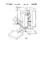
- FIG. 1 shows a schematical perspective view of the system of the invention, and a bag to be inflated and deflated,
- FIG. 2 shows a sectional view of the rotary distributor of the system of FIG. 1, for three different positions of its rotating piece
- FIG. 3 shows a block diagram of the electronic circuit of the system of FIG. 1,
- FIG. 4 shows the angular position of the rotary piece of the rotary distributor of FIG. 2 as a function of a control voltage
- FIG. 5 shows a timing diagram of the different signals of the electronic circuit of FIG. 3.
- FIG. 1 a system for inflating and deflating a flexible bag 1 intended here for an artificial heart.
- an artificial heart is formed of two ventricles, each comprising a flexible bag containing blood.
- the deformation of each blood bag for sucking up or delivering the blood is controlled by the deformation of a bag similar to the bag in FIG. 1, alternately inflated and deflated with, here, air.
- FIG. 1 For the sake of simplicity, although it requires two air bags for controlling the two ventricles of an artificial heart, only a single air bag 1 has been shown in FIG. 1.
- bag 1 communicates with the body 42 of a distributor, here rotary, through a duct 14.
- the body 42 of distributor 4 also communicates with an air reservoir 2 through a duct 24.
- a pump 3, here of known type with two toothed gear wheels, each wheel which is driven by a motor 31, is provided with an inlet and an outlet which communicate with the body 42 of distributor 4 through a duct 34 and through a duct 43, respectively.
- the distributor 4 includes a motor 41, with axis 44, which controls the position of a rotary piece in body 42, so as to place in communication:
- Bag 1 is provided with a pressure sensor 11.
- An electronic circuit 5 is connected to sensor 11, to the motor 41 of distributor 4 and to the motors 31 of pump 3 through connections 511, 541 and 531 respectively.
- FIG. 2 which is a sectional view perpendicular to axis 44 of body 42 of distributor 4 shows that this latter has a recess 46, inside which moves a rotary piece 45, driven by the motor 41.
- the recess 46 is here a cylindrical volume with circular base and center O where the axis 44 of FIG. 1 is projected.
- Four orifices 12, 22, 31 and 32 formed in the walls of recess 46 communicate with ducts 14, 24, 34 and 43 respectively, that is to say with bag 1, reservoir 2, the inlet and outlet of pump 3, respectively.
- the orifices 31 and 32 are formed in the cylindrical wall of recess 46, symmetrical with respect to each other relatively to the axis 44 and here symmetrical with respect to the horizontal plane, in FIG. 2, passing through the axis 44.
- the orifices 12 and 22 are formed in one of the circular bases of recess 46. They are symmetrical with each other relatively to the axis 44 and here symmetrical with respect to the vertical plane, in FIG. 2, passing through the axis 44. They have substantially the shape of an ellipsis with large horizontal axis, in FIG. 2.
- the rotary piece 45 is a thick rectangular plate mounted for movement about axis 44 so that its four edges mate sealingly with the walls of recess 46.
- the thickness of the rotary piece 45 is slightly less, here, than the large axis of the elliptic orifices 12 and 22, and more particularly less than the dimension of orifices 31 and 32 in the plane of FIG. 2.
- angle ⁇ when ⁇ is close to the value ⁇ 1 , here equal to 30°, that is to say when piece 45 is in the position a of FIG. 2, orifices 31 and 22 communicate through the inner volume of recess 46, as moreover do the orifices 32 and 12.
- the position a corresponds then to inflation of the bag.
- ⁇ is close to the value ⁇ 2 , here equal to 75°, which corresponds to the position b in FIG. 2, orifices 31 and 22 continue to communicate, as well as orifices 32 and 12, but, because orifices 31 and 32 communicate together, with the thickness of piece 45 being less than their dimension, the bag 1 and reservoir 2 are placed in direct communication not passing through pump 3.
- the position b may then correspond to the situation in which bag 1 empties itself into reservor 2, if, of course, the pressure in bag 1 is greater than the pressure in reservoir 2.
- the rotary piece 45 must not theoretically be controlled so that ⁇ becomes greater than ⁇ 3 , but if that occurs following a false maneuver, orifices 12 and 22 each communicate at one and the same time with orifices 31 and 32, so that pump 3 is never in the situation where its inlet and its outlet are blocked.
- motor 44 controls piece 45 so that ⁇ varies from 167° to 120°, the distributor 4 places reservoir 2 and bag 1 progressively in communication through pump 3.
- the electronic circuit 5 will now be described with reference to FIG. 3.
- the electronic circuit comprises an electric energy source for supplying its different components with power, and is not shown in the FIG., for the sake of simplicity.
- the electronic circuit comprises first of all a reference signal generator 51, having two analog outputs delivering respectively a pressure reference signal CP and a coarse reference signal CG for distributor 4.
- the reference signal generator 51 is also provided with two binary outputs delivering respectively an inflation-deflation reference signal GD and a reference signal DP for deflation by the pump.
- An analog subtractor 52 receives at its plus input the signal CP and at its minus input, connected to connection 511, an analog signal P.
- the output of subtractor 52 is connected to the input of a first controllable switch 53 with two outputs, the control input of which receives the binary signal GD.
- the first output of switch 53 is connected to the input of a circuit 54 controlling the motors 31, which circuit has two outputs connected to connection 531, through a double switch 61, with a control input receiving the signal GD.
- the second output of switch 53 is connected to the input of a second controllable switch 55, with two outputs, whose control input receives the binary signal DP.
- the first output of switch 55 is connected through an inverting amplifier 56 to a first input of a third controllable switch 58, with two inputs and one output, the control input of which receives the binary signal DP.
- the second output of switch 55 is connected to the second input of switch 58, through a non inverting amplifier 57.
- switch 58 is connected to a first input of an analog adder 59, whose second input receives the signal CG and whose output delivers a signal CD to the input of a circuit 60 controlling motor 41, whose output is connected to the connection 541.
- the reference signal generator 51 is adapted so as to produce the four periodic signals CP, CG, GD and DP of period T, shown in FIG. 5 which will be described in further detail subsequently.
- the design of such a circuit is within the scope of a man skilled in the art and will not be described further here.
- Circuit 54 is adapted for supplying motors 31 with power so that their speed is an increasing function of the analog voltage applied to its input. Its design is then within the scope of a man skilled in the art.
- Circuit 60 is of known type which controls motor 41, here a stepper motor, so that the position of the rotary piece 45 of the distributor, defined by the angle ⁇ of FIG. 2, varies as a function of the signal CD applied to its input in accordance with a law, here linear, represented in FIG. 4, where the values CD1, CD2 and CD3 of the signal CD correspond to the above defined angles ⁇ 1 , ⁇ 2 and ⁇ 3 .
- the design of circuits 60 is also within the scope of a man skilled in the art.
- the system which has just been described operates as follows.
- the pressure reference signal CP follows a predetermined law which may be chosen arbitarily and which, in practice, is chosen so that the artificial heart controlled simulates as well as possible the operation of a real heart.
- FIG. 5 shows a typical trend for a cycle of duration T, which cycle may be divided into three phases, in the frequent case where the pressure in the reservoir is equal to the atmospheric pressure P atm .
- the first phase corresponds to the inflation phase of bag 1.
- the reference pressure increases, from the value P atm and as far as a maximum value P max .
- signal CG assumes the value CD1 and the signals GD and DP remain at the logic level O.
- the second phase corresponds to the initial deflation phase, during which the reference pressure decreases, while remaining greater than the atmospheric pressure P atm .
- the signal CG assumes the value CD2
- signal GD is at logic level 1
- signal DP is at logic level O.
- the third phase corresponds to the final deflation phase, during which the reference pressure becomes less than the atmospheric pressure P atm and here levels out at a minimum pressure P min .
- the signal CG assumes the value CD3, and signals GD and DP remain at logic level 1.
- the output of subtractor 52 which then represents the difference between the reference pressure and the pressure P measured by sensor 11, is applied by switch 53 controlled by signal GD at level O to the input of circuit 54. Since no signal is then applied to the input of switch 55, the signal CD is equal to the signal CG, that is to say to the value CD1 which causes the rotary piece to remain motionless in the position a of FIG. 2, that is to say in the inflation position.
- the error that is to say the difference between the reference pressure and the measured pressure P, controls the speed of motors 31, which reacts in its turn on the pressure in the bag, and circuit 54 is adapted so that the servo loop thus formed permanently ensures equality of pressure P and the reference pressure.
- the error signal at the output of subtractor 52 is applied through the inverting amplifier 56 to adder 59 and signal CD then represents the sum of the coarse reference signal CG of the distributor, at that time equal to CD2, and of the amplified error signal.
- signal CD deviates all the more from the values CD2 the higher the error signal. That results in moving the rotary piece 45 about the position b in FIG. 2, i.e. the progressive control for placing bag 1 and reservoir 2 in direct communication, which in its turn reacts on the pressure, and the amplifier 56 is adjusted so that the servo loop thus formed permanently ensures equality of the pressure P and the reference pressure.
- the inverting amplifier 56 is replaced by the non inverting amplifier 57 and the coarse reference signal CG of the distributor assumes the value CD3, which results in moving the rotary piece 45 about the position c in FIG. 2.
- the pump 3 which is still rotating because of its inertia, is used for emptying bag into reservoir 3, the progressive control of the rotary piece 45 about its position c being controlled, as before in the initial deflation phase, so as to permanently ensure equality of pressure P and the reference pressure.
- the invention is not limited to the description which has just been made thereof.
- the desired deflation time is too long, and the pressure P min to low for pump 3 to be able to maintain it in bag 1 by using the inertia alone, it would be within the scope of a man skilled in the art to alter the preceding arrangement so as to supply again motors 31 with power at the end of deflation.
- FIG. 1 is schematical.
- reservoir 2 is not external to the system, as in this FIG., but itself contains the system, for which it serves as housing.
Landscapes
- Health & Medical Sciences (AREA)
- Engineering & Computer Science (AREA)
- Heart & Thoracic Surgery (AREA)
- Anesthesiology (AREA)
- Cardiology (AREA)
- Mechanical Engineering (AREA)
- Biomedical Technology (AREA)
- Hematology (AREA)
- Life Sciences & Earth Sciences (AREA)
- Animal Behavior & Ethology (AREA)
- General Health & Medical Sciences (AREA)
- Public Health (AREA)
- Veterinary Medicine (AREA)
- Medical Informatics (AREA)
- External Artificial Organs (AREA)
Abstract
Description
Claims (14)
Applications Claiming Priority (2)
| Application Number | Priority Date | Filing Date | Title |
|---|---|---|---|
| FR8618332 | 1986-12-30 | ||
| FR8618332A FR2608927B1 (en) | 1986-12-30 | 1986-12-30 | INFLATION SYSTEM, PARTICULARLY FOR HEART ASSISTANCE |
Publications (1)
| Publication Number | Publication Date |
|---|---|
| US4865580A true US4865580A (en) | 1989-09-12 |
Family
ID=9342414
Family Applications (1)
| Application Number | Title | Priority Date | Filing Date |
|---|---|---|---|
| US07/137,937 Expired - Lifetime US4865580A (en) | 1986-12-30 | 1987-12-28 | Inflation system, in particular for cardiac assistance |
Country Status (2)
| Country | Link |
|---|---|
| US (1) | US4865580A (en) |
| FR (1) | FR2608927B1 (en) |
Cited By (1)
| Publication number | Priority date | Publication date | Assignee | Title |
|---|---|---|---|---|
| US20050186097A1 (en) * | 2001-06-22 | 2005-08-25 | Team Worldwide Corporation | Air pump assembly with switching pipe |
Citations (5)
| Publication number | Priority date | Publication date | Assignee | Title |
|---|---|---|---|---|
| US3783453A (en) * | 1971-12-23 | 1974-01-08 | V Bolie | Self-regulating artificial heart |
| DE2558921A1 (en) * | 1975-12-29 | 1977-07-07 | Siemens Ag | Pneumatic or hydraulic pulse pump drive - has circulatory pump with bypass in parallel with pulse pump drive |
| US4116589A (en) * | 1977-04-15 | 1978-09-26 | Avco Corporation | Extracorporeal pulsatile blood pump comprised of side by side bladders |
| US4381567A (en) * | 1981-09-15 | 1983-05-03 | Foxcroft Associates | Hydraulically actuated total cardiac prosthesis with reversible pump and three-way ventricular valving |
| FR2580339A1 (en) * | 1985-04-16 | 1986-10-17 | Sagem | ELECTRO-PNEUMATIC CONVERTER |
Family Cites Families (1)
| Publication number | Priority date | Publication date | Assignee | Title |
|---|---|---|---|---|
| FR2050011A5 (en) * | 1970-06-05 | 1971-03-26 | Faber Peter |
-
1986
- 1986-12-30 FR FR8618332A patent/FR2608927B1/en not_active Expired - Lifetime
-
1987
- 1987-12-28 US US07/137,937 patent/US4865580A/en not_active Expired - Lifetime
Patent Citations (6)
| Publication number | Priority date | Publication date | Assignee | Title |
|---|---|---|---|---|
| US3783453A (en) * | 1971-12-23 | 1974-01-08 | V Bolie | Self-regulating artificial heart |
| DE2558921A1 (en) * | 1975-12-29 | 1977-07-07 | Siemens Ag | Pneumatic or hydraulic pulse pump drive - has circulatory pump with bypass in parallel with pulse pump drive |
| US4116589A (en) * | 1977-04-15 | 1978-09-26 | Avco Corporation | Extracorporeal pulsatile blood pump comprised of side by side bladders |
| US4381567A (en) * | 1981-09-15 | 1983-05-03 | Foxcroft Associates | Hydraulically actuated total cardiac prosthesis with reversible pump and three-way ventricular valving |
| FR2580339A1 (en) * | 1985-04-16 | 1986-10-17 | Sagem | ELECTRO-PNEUMATIC CONVERTER |
| US4718833A (en) * | 1985-04-16 | 1988-01-12 | Societe D'applications Generales D'electricite, Et De Mecanique Sagem | Electropneumatic converter |
Cited By (6)
| Publication number | Priority date | Publication date | Assignee | Title |
|---|---|---|---|---|
| US20050186097A1 (en) * | 2001-06-22 | 2005-08-25 | Team Worldwide Corporation | Air pump assembly with switching pipe |
| US7040347B2 (en) * | 2001-06-22 | 2006-05-09 | Team Worldwide Corporation | Air pump assembly with switching pipe |
| US20060112492A1 (en) * | 2001-06-22 | 2006-06-01 | Team Worldwide Corporaton | Inflatable product with built-in housing and switching pipe |
| US20070000061A1 (en) * | 2001-06-22 | 2007-01-04 | Team Worldwide Corporation | Inflatable product provided with electric air pump |
| US7246394B2 (en) | 2001-06-22 | 2007-07-24 | Team Worldwide Corporation | Inflatable product with built-in housing and switching pipe |
| US7313837B2 (en) | 2001-06-22 | 2008-01-01 | Team Worldwide Corporation | Inflatable product provided with electric air pump |
Also Published As
| Publication number | Publication date |
|---|---|
| FR2608927A1 (en) | 1988-07-01 |
| FR2608927B1 (en) | 1996-12-20 |
Similar Documents
| Publication | Publication Date | Title |
|---|---|---|
| CA2322626A1 (en) | Pressure control system for cardiac assist device | |
| US5299599A (en) | Valving arrangement for a negative pressure ventilator | |
| US4634430A (en) | Pump arrangement for medical purposes | |
| US3885554A (en) | Apparatus for generating pulses of fluid pressure | |
| US7244224B2 (en) | Pump driving unit for driving a pump used for supporting or substitution of cardiac function | |
| US5064353A (en) | Pressure responsive linear motor driven pump | |
| JP3265650B2 (en) | Blood circulation assist device | |
| US4086920A (en) | Intermittent inflatable apparatus | |
| US5850835A (en) | Respirator system | |
| US4858596A (en) | Portable sequential compression device | |
| US5711757A (en) | Controller especially for pneumatic continuous passive motion devices | |
| GB2103842A (en) | Pneumatic control system for a pressure wave device | |
| DE3663619D1 (en) | Circulatory and coronary intra-aortic balloon assistance pump | |
| GB1526693A (en) | Apparatus for aiding the blood flow in patients | |
| US4787368A (en) | Medical device driving system | |
| JPH0516870B2 (en) | ||
| CA2089238A1 (en) | Aspiration Control System | |
| US4135500A (en) | Apparatus for oscillating flotation support systems | |
| CA2021568A1 (en) | Implantable artificial sphincter system | |
| IE821867L (en) | Pneumatic therapeutic apparatus | |
| JPS58169462A (en) | Artificial heart drive apparatus | |
| US4865580A (en) | Inflation system, in particular for cardiac assistance | |
| US5467772A (en) | Automatic sphygmomanometer | |
| FR2251302A1 (en) | Externally controlled artificial sphincter - external electromagnet actuates motor controlling valve balloon inflation | |
| ES2003450A6 (en) | Supplying pneumatically controlled appliances |
Legal Events
| Date | Code | Title | Description |
|---|---|---|---|
| AS | Assignment |
Owner name: SOCIETE D'APPLICATIONS GENERALES D'ELECTRICITE ET, Free format text: ASSIGNMENT OF ASSIGNORS INTEREST.;ASSIGNORS:BERGER, HENRI;VERAGEN, RENE;REEL/FRAME:004815/0519 Effective date: 19871205 Owner name: SOCIETE D'APPLICATIONS GENERALES D'ELECTRICITE ET Free format text: ASSIGNMENT OF ASSIGNORS INTEREST;ASSIGNORS:BERGER, HENRI;VERAGEN, RENE;REEL/FRAME:004815/0519 Effective date: 19871205 |
|
| STCF | Information on status: patent grant |
Free format text: PATENTED CASE |
|
| FEPP | Fee payment procedure |
Free format text: PAYOR NUMBER ASSIGNED (ORIGINAL EVENT CODE: ASPN); ENTITY STATUS OF PATENT OWNER: LARGE ENTITY |
|
| REMI | Maintenance fee reminder mailed | ||
| FPAY | Fee payment |
Year of fee payment: 4 |
|
| SULP | Surcharge for late payment | ||
| FEPP | Fee payment procedure |
Free format text: PAYOR NUMBER ASSIGNED (ORIGINAL EVENT CODE: ASPN); ENTITY STATUS OF PATENT OWNER: LARGE ENTITY Free format text: PAYER NUMBER DE-ASSIGNED (ORIGINAL EVENT CODE: RMPN); ENTITY STATUS OF PATENT OWNER: LARGE ENTITY |
|
| FPAY | Fee payment |
Year of fee payment: 8 |
|
| FPAY | Fee payment |
Year of fee payment: 12 |