US4864800A - Device and method for bagging thin flexible members - Google Patents
Device and method for bagging thin flexible members Download PDFInfo
- Publication number
- US4864800A US4864800A US07/186,565 US18656588A US4864800A US 4864800 A US4864800 A US 4864800A US 18656588 A US18656588 A US 18656588A US 4864800 A US4864800 A US 4864800A
- Authority
- US
- United States
- Prior art keywords
- bag
- stack
- chute
- pan
- opening
- Prior art date
- Legal status (The legal status is an assumption and is not a legal conclusion. Google has not performed a legal analysis and makes no representation as to the accuracy of the status listed.)
- Expired - Lifetime
Links
Images


Classifications
-
- B—PERFORMING OPERATIONS; TRANSPORTING
- B65—CONVEYING; PACKING; STORING; HANDLING THIN OR FILAMENTARY MATERIAL
- B65B—MACHINES, APPARATUS OR DEVICES FOR, OR METHODS OF, PACKAGING ARTICLES OR MATERIALS; UNPACKING
- B65B5/00—Packaging individual articles in containers or receptacles, e.g. bags, sacks, boxes, cartons, cans, jars
- B65B5/06—Packaging groups of articles, the groups being treated as single articles
- B65B5/067—Packaging groups of articles, the groups being treated as single articles in bags
-
- B—PERFORMING OPERATIONS; TRANSPORTING
- B65—CONVEYING; PACKING; STORING; HANDLING THIN OR FILAMENTARY MATERIAL
- B65B—MACHINES, APPARATUS OR DEVICES FOR, OR METHODS OF, PACKAGING ARTICLES OR MATERIALS; UNPACKING
- B65B39/00—Nozzles, funnels or guides for introducing articles or materials into containers or wrappers
- B65B39/12—Nozzles, funnels or guides for introducing articles or materials into containers or wrappers movable towards or away from container or wrapper during filling or depositing
Definitions
- the field of the present invention relates to methods and devices for bagging a stack of thin flexible members.
- One automatic bagging device takes two sheets of sealable material, positions one layer over the stack and one layer beneath the stack, and seals the two layers together at the edges. This device produces a bagged goods of a different appearance to the desired look of a bag of tortillas expected by consumers and also requires a complicated sealing process where all sides of the bag must be sealed after insertion of the product.
- the stack should be fully and gently moved and supported throughout the bagging process, the integrity of the stack should be maintained (i.e., keep the stack straight), and the stack of tortillas should have a close fit within the bag to minimize bagging material costs.
- the present invention is directed to a device and method for bagging thin flexible members. More particularly the invention is directed to bagging tortillas or other thin flexible dough members which may be stacked such as pitas, mushu pork wrappers, egg roll wrappers and the like. Actually the present invention may also be applicable to non-food items such as paper goods, flexible thin plastic members, leather or vinyl goods, articles of clothing, or the like.
- the present invention may be applied to bag a stack of one or more flexible members--items which may typically be laid relatively flat and horizontal, and if desired stacked vertically.
- a stack of tortillas may be placed on a curved pan or chute and a bag is drawn into position next to the stack on the pan with the bag being open toward the stack.
- the curved pan with the stack thereon may then be moved into the bag.
- the bag may be removed from the holder.
- the curved pan with the stack thereon and the bag therearound reaches a conveying means, the curved pan is abruptly stopped and/or reversed allowing the momentum of the stack to pull the bag off of the pan and slide onto a conveyor means.
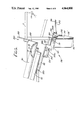
- FIG. 1 is a diagrammatic side elevation view of a bagging mechanism according to the present invention
- FIG. 2 is an enlarged and detailed side elevation view of the bagging mechanism of FIG. 1;
- FIG. 2a is a perspective view of the forming pan of FIG. 2;
- FIG. 2b is a cross-sectional view of FIG. 2 taken along the line 2b-2b;
- FIG. 2c is a cross-sectional view of FIG. 2 taken along the line 2c-2c;
- FIG. 3 is an end view of the bagging head means and its actuator
- FIG. 4 is a plan view of the bagging head means of the preferred embodiment
- FIG. 5 is a cross-sectional view of the tortillas in a curved pan as in FIG. 2 or FIG. 6 taken along the line 5--5;
- FIG. 6 is a side elevation view of an alternative embodiment of the bagging head means
- FIG. 7 and FIG. 8 are side elevation views of the alternative embodiment of the bagging head means showing two operative positions of the bagging process
- FIG. 9 is a detailed plan view of the alternative embodiment of the bagging head means.
- FIG. 10 is a perspective view of a single bag usable in the present invention.
- FIG. 11 is a perspective view of a bag opened by the prongs of a bagging head means according to the alternative embodiment of the present invention.
- FIG. 12 is a cross-sectional view taken substantially along the line 12--12 of FIG. 7 showing how a stack of tortillas in a pan fits into an opened bag.
- FIGS. 1 and 2 generally illustrate a device of the preferred embodiment which may be used for bagging a stack of thin flexible members such as tortillas.
- a stack of tortillas 15 is conveyed into position along an inlet conveyor 10 where the stack 15 is grabbed between a belt 30 and a belt 40.
- the belt 40 rotates around pulleys 42 and 44.
- An additional pulley 46 is located adjacent the pulley 42 to provide additional clearance for elements below the belt 40.
- the pulley 46 if adjustably mounted may also provide a tensioning means for the belt 40.
- the belt 30 rotates between pulleys 32 and 34 which are rotatably connected at the opposite ends of a tubular pulley frame member 60.
- pulleys 32 and 34 are rotatably connected at the opposite ends of a tubular pulley frame member 60.
- the pulley 32 is rotatably secured on a drive arm 36 and to a frame arm 60a.
- the frame arm 60a is attached to a tubular pulley frame member 60.
- the upstream end of this unit for the upper belt 30 is supported by a flexible strap 36a attached between the drive arm 36 and the main frame 5 such that when a stack of tortillas 15 enters between pulleys 32 and 42, the pulley 32 may float vertically to accommodate a variable height stack of tortillas while the weight of the components applies the desired compressive force thereon.
- the length of the strap 36a may be varied to adjust the resting position of the upstream end of the belt 30.
- the downstream pulley 34 is rotatably connected to arm 39 which is in turn attached to the frame member 60.
- Pulley 34 may also move vertically by means of a cylinder 38 which is attached to a follower arm 39.
- the arm 39 is connected to the pulley shaft about which the pulley 34 rotates.
- Cylinder 38 operates as a biasing means or spring to provide downward pressure to the pulley 34. The pressure applied is selected so as to compress the stack 15 for proper bending.
- a drive means is provided to rotate belts 30 and 40 at the same speed.
- a motor 22 rotates a primary drive pulley 24 at a rate which produces the desired belt speed.
- the primary drive belt 20 is rotated by the primary drive pulley 24 and in turn drives the belt 40 by rotating the pulley 42 in a clockwise direction as viewed in FIGS. 1 and 2.
- the belt 30 is driven in a counter clockwise direction as viewed in FIGS. 1 and 2 as the primary belt rotates pulley 26, which in turn drives pulley 32 through secondary drive belt 25.
- the pulley 28 allows return of the drive belt 20 to the primary drive pulley 24.
- the stack 15 is slid onto the end of a curved chute or pan 50.
- the belts 30 and 40 are only approximately 1 inch in width and grip the stack 15 therebetween, slightly compressing the stack 15, and eventually depositing the stack 15 at the end of the chute 50.
- the width of the belts 30 and 40 and the compression force applied may be chosen depending on the item being bagged.
- the belt 30 may also be supported by a curved folder arm 60 on each side of the upper belt 30.
- the stack of tortillas is preferably bent into a "U" shape for insertion into a bag.
- the preferred means for bending has a forming pan 45 along the upper flight of the lower belt 40 extending from near the inlet conveyor 10 to the curved chute 50.
- the sides of the forming pan 45 begin in a flat or horizontal position at pulley 42 where the stack of tortillas is originally placed on the forming pan 45, and then the sides of forming pan 45 gradually curve upward (see FIG. 2c) until the cross-section of the forming pan 45 is in a "U" shape (see FIG. 2b) which corresponds to the curved chute 50.
- the upper flight of the lower belt 40 contacts the stack of tortillas and slides along the top of the forming pan 45.
- the downstream end of the forming pan 45 may actually fit inside the curved chute 50 so that as the belts 30 and 40 slide the stack 15 along the forming pan 45, the stack is gently bent and then neatly dropped into the curved chute 50.
- the curved chute 50 has a slot in its bottom near its upstream end fitting around the belt 40 and the pulley 44.
- the curved chute 50 may be extended back (this alternative not shown) to the inlet conveyor 10.
- the chute 50 would have a slot or opening at the bottom along its axis to permit the belt 40 to contact the stack of tortillas 15.
- the sides of chute 50 would begin in a flat or horizontal position at pulley 42 where the stack of tortillas would be originally placed on the chute 50, and then the sides of chute 50 would gradually curve upward until the cross-section of chute 50 is in a "U" shape as viewed in the cross-section of FIG. 5.
- the chute 50 as illustrated may be in operation moving a stack toward the outlet conveyor 130 while simultaneously another stack is being moved along the forming pan 45.
- the chute 50 is moved longitudinally forward into an open bag which is opened and positioned by a bagging head means generally depicted by numeral 90 which will be described in greater detail below.
- the rear end of the chute 50 is connected through a chute connector 52 to a chute actuator mechanism 70 which provides the desired longitudinal moving action for the chute 50.
- the bagging head means 90 provides means to position and open a bag adjacent to the chute 50 allowing the chute 50 with the tortilla stack 15 thereon to be inserted into the open bag.
- the chute 50 travels forward, the bag is removed from the bagging head 90 and the chute 50, with the stack thereon and with a bag therearound, are moved toward an outlet conveyor 130.
- the chute 50 is abruptly stopped and/or reversed and the momentum of the stack of tortillas 15 pulls the bag off the chute 50 gently depositing onto the outlet conveying means 130.
- the outlet conveying means 130 then transfers the bagged stack of tortillas to the bag sealer 140 which may be activated by sensor means 135.
- a bag dispenser may be provided which includes plurality of bags 155 placed upon a wicket 150.
- the wicket 150 is slanted at a downward angle so the bags 155 may slide downward into position to be grabbed by the bagging head means 90.
- the bagging head means 90 also includes a linkage movement assembly or bag positioning means generally depicted as numeral 80 which is comprised of an actuator 82 and links 84, 86, and 88. The bagging head means 90 is moved from the position adjacent the bags 155 to the position adjacent the chute 50 through the linkage movement assembly 80.
- the linkage movement assembly 80 is operated by the actuator 82 which is pivotally attached to the frame 5 at a connection point 82a.
- the actuator 82 is pivotally attached to a first link 84 at a pivot point 84b.
- the first link 84 is pivotally connected to frame 5 at a pivot point 84a.
- a second link 86 is pivotally connected a second end of first link 84 at a connector 86a.
- a second end of second link 86 is pivotally connected to a third link 88 at a connector 88b.
- the third link 88 is connected at a second end to frame 5 at a connector 88a. Therefore as actuator 82 extends and retracts, the bagging head means 90, which is basically connected to second link 86, moves from its position at the stack of bags 155 to its position adjacent chute 50.
- FIG. 3 illustrates the bagging head means 90 having two prongs or fingers 92, 92 and a shoe 94 which are insertable into a bag 155'.
- Each prong 92 is attached to a prong arm 92a which pivots about a connector 104b.
- An arm linkage 104 also pivoting about connector 104b is attached to the prong arm 92a.
- a main linkage 102 is pivotally connected to a second end of each arm linkage 104, 104 and connectors 104a, 104a.
- An actuator 100 attached at one end to base 87 has its second end pivotally attached at connector 100b to main linkage 102. Therefore, as actuator 100 extends and retracts, the prongs 92, 92 go from the retracted condition to the extended position (which is represented in phantom in FIG. 3).
- the position of connector 100b of actuator 100 to the link 102 may be adjusted by an adjusting means 103.
- FIGS. 6-9 illustrate an alternative embodiment for the bagging head means previously described.
- the alternative embodiment bagging head means is generally depicted by numeral 190.
- FIGS. 6-12 also functionally depict the bagging process which is applicable either to the preferred embodiment above or to the alternative embodiment to be described.
- FIG. 6 illustrates a stack of tortillas 15 already placed on the curved chute 50 awaiting insertion into a bag.
- the chute 50 will be moved forward upon actuation of the cylinder 52 at the appropriate time.
- a puff of air is ejected out of puffer tube 110 into a bag 155' in order to open the bag 155' sufficiently to allow air from the blower 115 to enter and inflate the bag 155' thereby allowing the insertion of the prongs 192 and 194.
- the blower 115 blows air at a higher volume but at a lower pressure than the air of puffer tube 110.
- the puffer tube 110 may be connected to a compressed air supply while the blower 115 may be comprised of an air fan unit.
- bag 155' is now in position adjacent the stack of tortillas 15 on the curved pan 50.
- the four prongs 192 and 194 have separated and fully opened the bag 155' into a trapezoidal shape which readily accepts the insertion of the stack of tortillas 15 on the curved pan 50.
- the curved pan 50 has been moved forward removing the bag 155' from the prongs 192 and 194 bringing the stack of tortillas 15' in the bag 155' toward the conveyor 130.
- the motion of the curved pan 50 is abruptly stopped and/or reversed and the momentum of the stack of tortillas 15' pulls the bag 155' with the stack of tortillas 15' therein off of the curved pan 50 and onto the outlet conveyor 130.
- FIG. 10 illustrates a typical bag 155' which hangs on the two prong wicket 150 which slides through holes 157, 157 in the top portion 155a of bag 155'.
- An access line 157a such as a slit or perforation above each hole 157 allows for easy tearing or removal of a bag 155' from the wicket 150 by the bagging head means. After the stack of tortillas is bagged, the top portion 155a of the bag 155' may be removed if desired.
- the alternate bagging head means 190 of the FIGS. 6-9 will now be described in detail.
- a plurality of bags 155 hangs down on a bag wicket 150 from which the bagging head means 190 can remove a bag 155' from a position illustrated in FIG. 6 to the open position as illustrated in FIG. 7.
- the bagging head means 190 includes a positioning and an opening means.
- the positioning means is comprised of a cylinder 182 which is pivotally connected to the frame 5 at point 182a.
- the bag opening means On the opposite end of the cylinder 182 is the bag opening means which is pivotally connected at point 182b.
- the bag opening means is comprised of a main frame 210 on which an actuator 212 is positioned longitudinally as best viewed in FIG. 9.
- a pair of tie rods 200, 200 are pivotally connected to the actuator head 214 on the actuator 212 at pivot points 200a, 200a.
- the tie rods 200, 200 are pivotally connected to slider members 198, 198 at pivot points 200b, 200b.
- Each slider member 198 slides along extender rods 196 and 202.
- a pair of bag prongs 194, 194 extend outward from the base 210 of the bag opening means and a moveable bag prong 192 extends outward from each slider member 198.
- the tie rods 200, 200 slide the slider members 198, 198 along rods 196, 196 thereby opening a bag with the bag prongs 194, 194 and the moveable prongs 192, 192.
- FIGS. 6-8 also illustrate a tortilla stack stopping device generally depicted as element 220.
- the stack stopping device 220 is comprised of an actuator 222 which extends and retracts a stopper rod 224.
- the stopper rod 224 When a stack of tortillas 15 is deposited onto the pan 50, the stopper rod 224 is in the extended position as viewed FIG. 6 preventing the stack 15 from sliding off the end of the chute 50.
- the stopper rod 224 is retracted as viewed in FIGS. 7 and 8.
- the preferred embodiment does not require the stack stopping device 220 but includes means for adjusting the relative speeds of the moving chute 50 and the belts 30 and 40. If the stack 15 does not slide far enough or slides too far down or off the chute 50, several adjustments may be made including: (1) increasing or decreasing the speed of the belts 30 and 40 to deposit the stack 15 properly at the end of chute 50; (2) increasing or decreasing the speed of the chute 50; and/or (3) adjusting the moment the chute 50 begins moving as a stack 15 is placed thereon.
- the speed of the chute 50 may be increased by increasing the stroke speed of the chute actuator 52.
- the speed of the belts 30 and 40 could be reduced for example by reducing the speed of the motor 22.
- a third possible adjustment is to commence the movement of the chute 50 earlier in response to the detector means 120 sensing the deposit of a stack 15 onto the chute 50.
- a stack of tortillas is formed into a U-shape to reduce its outside perimeter whereby a bag of a desired size can be fitted readily over the tortilla stack by a mechanical bag opening means with adequate clearance to insure consistent operation and yet when the tortilla stack is allowed to flatten, it tightly fits in the bag.
- the result is a most desirable package from the standpoint of appearance, maintaining a straight stack, minimizing bag material, easing of subsequent handling, and the like.
- the device may provide support for the item being inserted into the bag and does not push the item into the bag from one end.
- the item is fully supported resting on the curved chute 50. Therefore the item does not require rigidity or stiffness in order to be readily inserted into a bag.
- the item is not crumpled or otherwise damaged.
- the stack would crumple and bunch up possibly damaging the tortillas.
- the present invention has solved this problem.
Abstract
Description
Claims (21)
Priority Applications (1)
| Application Number | Priority Date | Filing Date | Title |
|---|---|---|---|
| US07/186,565 US4864800A (en) | 1988-04-27 | 1988-04-27 | Device and method for bagging thin flexible members |
Applications Claiming Priority (1)
| Application Number | Priority Date | Filing Date | Title |
|---|---|---|---|
| US07/186,565 US4864800A (en) | 1988-04-27 | 1988-04-27 | Device and method for bagging thin flexible members |
Publications (1)
| Publication Number | Publication Date |
|---|---|
| US4864800A true US4864800A (en) | 1989-09-12 |
Family
ID=22685443
Family Applications (1)
| Application Number | Title | Priority Date | Filing Date |
|---|---|---|---|
| US07/186,565 Expired - Lifetime US4864800A (en) | 1988-04-27 | 1988-04-27 | Device and method for bagging thin flexible members |
Country Status (1)
| Country | Link |
|---|---|
| US (1) | US4864800A (en) |
Cited By (7)
| Publication number | Priority date | Publication date | Assignee | Title |
|---|---|---|---|---|
| EP0464884A1 (en) * | 1990-06-28 | 1992-01-08 | Dott. Bonapace & C. S.p.A. | Method and apparatus for automatic bag packaging of hams, meats and food products in general |
| US5123232A (en) * | 1989-02-10 | 1992-06-23 | W. Kordes' Sohne Rosenschulen Gmbh & Co Kg | Apparatus for filling bags with unwieldy goods |
| US5191751A (en) * | 1989-11-20 | 1993-03-09 | Pitney Bowes Inc. | Envelope opening apparatus |
| US6182424B1 (en) * | 1998-09-11 | 2001-02-06 | Quest Packaging Inc. | Packaging apparatus and method |
| US6351926B1 (en) | 2000-01-19 | 2002-03-05 | Automated Packaging Systems, Inc. | Packaging system |
| US20030230050A1 (en) * | 2002-04-18 | 2003-12-18 | Pfankuch Maschinen Gmbh | Apparatus for filling foil bags |
| US20220018978A1 (en) * | 2018-11-29 | 2022-01-20 | Oy Ajat Ltd. | Detector circuit |
Citations (5)
| Publication number | Priority date | Publication date | Assignee | Title |
|---|---|---|---|---|
| US1992166A (en) * | 1933-11-03 | 1935-02-26 | Pure Made Products Co | Sliced loaf bagging device |
| US2656082A (en) * | 1951-10-24 | 1953-10-20 | Robert B Brown | Device for packaging flat flexible articles |
| US3022620A (en) * | 1959-11-17 | 1962-02-27 | Thes De L Elephant Soc D | Automatic machine for packing articles such as bags in thermoweldable pouches |
| US3699741A (en) * | 1971-07-09 | 1972-10-24 | Richard R Norman | Automatic bag packing apparatus for check-out |
| US4219989A (en) * | 1979-07-26 | 1980-09-02 | Star Packaging Corporation | Bagging apparatus |
-
1988
- 1988-04-27 US US07/186,565 patent/US4864800A/en not_active Expired - Lifetime
Patent Citations (5)
| Publication number | Priority date | Publication date | Assignee | Title |
|---|---|---|---|---|
| US1992166A (en) * | 1933-11-03 | 1935-02-26 | Pure Made Products Co | Sliced loaf bagging device |
| US2656082A (en) * | 1951-10-24 | 1953-10-20 | Robert B Brown | Device for packaging flat flexible articles |
| US3022620A (en) * | 1959-11-17 | 1962-02-27 | Thes De L Elephant Soc D | Automatic machine for packing articles such as bags in thermoweldable pouches |
| US3699741A (en) * | 1971-07-09 | 1972-10-24 | Richard R Norman | Automatic bag packing apparatus for check-out |
| US4219989A (en) * | 1979-07-26 | 1980-09-02 | Star Packaging Corporation | Bagging apparatus |
Cited By (8)
| Publication number | Priority date | Publication date | Assignee | Title |
|---|---|---|---|---|
| US5123232A (en) * | 1989-02-10 | 1992-06-23 | W. Kordes' Sohne Rosenschulen Gmbh & Co Kg | Apparatus for filling bags with unwieldy goods |
| US5191751A (en) * | 1989-11-20 | 1993-03-09 | Pitney Bowes Inc. | Envelope opening apparatus |
| EP0464884A1 (en) * | 1990-06-28 | 1992-01-08 | Dott. Bonapace & C. S.p.A. | Method and apparatus for automatic bag packaging of hams, meats and food products in general |
| US6182424B1 (en) * | 1998-09-11 | 2001-02-06 | Quest Packaging Inc. | Packaging apparatus and method |
| US6351926B1 (en) | 2000-01-19 | 2002-03-05 | Automated Packaging Systems, Inc. | Packaging system |
| US20030230050A1 (en) * | 2002-04-18 | 2003-12-18 | Pfankuch Maschinen Gmbh | Apparatus for filling foil bags |
| US20220018978A1 (en) * | 2018-11-29 | 2022-01-20 | Oy Ajat Ltd. | Detector circuit |
| US11921244B2 (en) * | 2018-11-29 | 2024-03-05 | Oy Direct Conversion Ltd. | Detector circuit |
Similar Documents
| Publication | Publication Date | Title |
|---|---|---|
| US4078358A (en) | Bag-hanging and bag-filling machines adapted for synchronous and independent operation and method of using same | |
| US4106260A (en) | Article folding and packaging system | |
| US4242854A (en) | Automatic bag loader | |
| RU2054364C1 (en) | Device for putting on sacks for loose products with item-by-item gripping of sacks | |
| US4457124A (en) | Bag-packaging machine for bread | |
| US7922639B2 (en) | Taco shell nesting apparatus and method | |
| JP2002537187A (en) | Bag filling apparatus and method | |
| US20030200729A1 (en) | Bag filling and sealing machine and method for handling bags | |
| JPH08337217A (en) | Packaging material supplying apparatus | |
| US4141392A (en) | Apparatus for automatic insertion of valved bags on bag-filling machines | |
| US4864800A (en) | Device and method for bagging thin flexible members | |
| US5483786A (en) | Apparatus for packaging articles | |
| CA1058127A (en) | Packaging machines | |
| NZ202791A (en) | Machine for sequentially opening plastics bags prior to filling with solid articles | |
| US5463845A (en) | Apparatus for folding, filling, and sealing microwave popcorn bags | |
| JPH0422766B2 (en) | ||
| US5720156A (en) | Case packing apparatus and method | |
| US5689931A (en) | Case erector with A-B detection | |
| US4513559A (en) | Bag transporter, folder and loader and method for operation | |
| WO1995015888A2 (en) | Apparatus for folding, filling and sealing bags with a fixture for holding the bag during the procedure | |
| WO2002012069A1 (en) | System and method for including inserts with goods during automated packaging | |
| CA1202009A (en) | Apparatus for folding and loading thin, limp, sheet- like articles into a receptacle | |
| JP3833590B2 (en) | Bag conveyor | |
| US4995225A (en) | Compact food tray film wrapping machine | |
| US4514957A (en) | Bag loading machine |
Legal Events
| Date | Code | Title | Description |
|---|---|---|---|
| AS | Assignment |
Owner name: FAMOSO EQUIPMENT CO., INC., A NV CORP., NEVADA Free format text: ASSIGNMENT OF ASSIGNORS INTEREST.;ASSIGNORS:BANYS, ALGIS R.;WELSH, RICHARD S.;REEL/FRAME:005072/0841 Effective date: 19890421 |
|
| STCF | Information on status: patent grant |
Free format text: PATENTED CASE |
|
| FEPP | Fee payment procedure |
Free format text: PAYOR NUMBER ASSIGNED (ORIGINAL EVENT CODE: ASPN); ENTITY STATUS OF PATENT OWNER: SMALL ENTITY |
|
| FPAY | Fee payment |
Year of fee payment: 4 |
|
| AS | Assignment |
Owner name: CASA HERRERA, INC. Free format text: ASSIGNMENT OF ASSIGNORS INTEREST;ASSIGNOR:FAMOSO EQUIPMENT CO., INC.;REEL/FRAME:007403/0307 Effective date: 19950323 |
|
| FEPP | Fee payment procedure |
Free format text: PAYER NUMBER DE-ASSIGNED (ORIGINAL EVENT CODE: RMPN); ENTITY STATUS OF PATENT OWNER: SMALL ENTITY |
|
| FPAY | Fee payment |
Year of fee payment: 8 |
|
| FPAY | Fee payment |
Year of fee payment: 12 |