US4864080A - Terminator connector fitting for electrical box and conduit system - Google Patents
Terminator connector fitting for electrical box and conduit system Download PDFInfo
- Publication number
- US4864080A US4864080A US07/056,424 US5642487A US4864080A US 4864080 A US4864080 A US 4864080A US 5642487 A US5642487 A US 5642487A US 4864080 A US4864080 A US 4864080A
- Authority
- US
- United States
- Prior art keywords
- box
- collar
- free end
- fitting
- wedge
- Prior art date
- Legal status (The legal status is an assumption and is not a legal conclusion. Google has not performed a legal analysis and makes no representation as to the accuracy of the status listed.)
- Expired - Fee Related
Links
Images

Classifications
-
- H—ELECTRICITY
- H02—GENERATION; CONVERSION OR DISTRIBUTION OF ELECTRIC POWER
- H02G—INSTALLATION OF ELECTRIC CABLES OR LINES, OR OF COMBINED OPTICAL AND ELECTRIC CABLES OR LINES
- H02G3/00—Installations of electric cables or lines or protective tubing therefor in or on buildings, equivalent structures or vehicles
- H02G3/02—Details
- H02G3/06—Joints for connecting lengths of protective tubing or channels, to each other or to casings, e.g. to distribution boxes; Ensuring electrical continuity in the joint
- H02G3/0616—Joints for connecting tubing to casing
- H02G3/0691—Fixing tubing to casing by auxiliary means co-operating with indentations of the tubing, e.g. with tubing-convolutions
-
- Y—GENERAL TAGGING OF NEW TECHNOLOGICAL DEVELOPMENTS; GENERAL TAGGING OF CROSS-SECTIONAL TECHNOLOGIES SPANNING OVER SEVERAL SECTIONS OF THE IPC; TECHNICAL SUBJECTS COVERED BY FORMER USPC CROSS-REFERENCE ART COLLECTIONS [XRACs] AND DIGESTS
- Y10—TECHNICAL SUBJECTS COVERED BY FORMER USPC
- Y10S—TECHNICAL SUBJECTS COVERED BY FORMER USPC CROSS-REFERENCE ART COLLECTIONS [XRACs] AND DIGESTS
- Y10S285/00—Pipe joints or couplings
- Y10S285/903—Corrugated
Definitions
- This invention relates to an electrical conduit system which includes a flexible corrugated conduit, an electrical outlet box of synthetic resin and a terminator connector fitting by which the corrugated conduit is connected to the electrical outlet box.
- the invention more specifically relates, in one aspect and without limitation, to a novel terminator connector fitting which is snapped into an opening in an electrical outlet box, and is used to connect to the outlet box, a flexible corrugated conduit which functions as a raceway for electrical conductors extended into the box and connected to terminals therewithin.
- U.S. Pat. No. 4,494,779 assigned to the assignee of the present invention, describes a terminator connector fitting by which corrugated conduit is connected to an electrical outlet box.
- the terminator fitting and the corrugated conduit are made of a synthetic resin material, and are characterized by flexibility and limited resiliency.
- the terminator fitting described in U.S. Pat. No. 4,494,779 is adapted to be forced, as facilitated by the resilient yielding of parts of the fitting, partially through an opening in a side wall of an electrical outlet box. The terminator fitting then snaps into position as the portion of the box defining this opening engages a recess or groove formed in the terminator fitting.
- the terminator fitting includes a pair of semi-cylindrical collars which can be interconnected, and each of which carries two spaced, box-engaging projections which extend axially from each of the collars and are yieldable radially inwardly sufficiently to permit them to be forced through the opening in the electrical outlet box.
- the inner side of each of the semi-cylindrical collars is grooved and ribbed to mate with, and engage, corrugations carried on a corrugated conduit to be connected to the electrical outlet box.
- Each box-engaging projection includes a wedge-shaped free end portion, and also a web portion by which the wedge-shaped free end portion is connected to the respective semi-cylindrical collar upon which it is carried.
- Each wedge-shaped end portion, associated web portion, and the semi-cylindrical collar to which the respective web portion is connected define an arcuate channel, groove or relief for receiving and engaging the portion of the wall of the electrical box which surrounds and defines the opening into which the terminator fitting is snapped in assembling the system.
- Each of the box-engaging projections is spaced from the adjacent box-engaging projection by a substantial circumferential distance, considered as an arc of a circle, and this spacing serves several functions. First, it requires less material when the terminator fitting is molded of plastic. More importantly, the spacing allows the arcuate dimension of each of the box-engaging projections to be sufficiently small that the respective projection can flex or bend about the web portion by which the respective box-engaging projection is connected to the semi-cylindrical collar upon which it is carried. Further, in providing the circumferential space between adjacent box-engaging projections, each of these projections can flex or bend in a radially inwardly direction as much as is required to permit it to be passed through the generally circular opening in an electrical outlet box.
- Such opening has a diametric dimension which is less than the outside diameter of the circle which passes through, and includes the largest outside dimension of the several box-engaging arcuate projections when they are collectively considered as a cylindrical array and are in a relaxed, undeflected condition. Without such spacing between the box-engaging projections, they would interfere with each other as they tend to flex radially inwardly, and such radially inward flexure would be limited, in many cases, to an extent such that the terminator fitting could not be forced through the opening in the wall of the electrical outlet box.
- This invention provides a terminator fitting of synthetic resin which can be quickly snapped into an opening provided in an electrical outlet box, and there function to retain a corrugated conduit in position relative to the box and the opening so that a system can thus be constructed which more effectively guides and protects electrical conductors used in a system of electrical service.
- the terminator fitting preferably, and most frequently, will be used with an electrical outlet box made of a synthetic resin material, and with a corrugated conduit also made of such material, the terminator fitting can be employed with metallic electrical outlet boxes.
- the terminator fitting of the invention preferably includes a pair of semi-cylindrical collars of substantially identical dimension, and which are preferably, but not necessarily, interconnected by a thin hinge strap which can be molded integrally with the semi-cylindrical synthetic resin collars.
- the collars cooperate, in use, to define, in collective array, a cylinder having a greater outside diameter than the diameter of the opening in the electrical outlet box into which the terminator fitting is to be inserted.
- the two collars may be molded as a single integral unit of cylindrical form.
- each collar carries a projection which may, in a preferred embodiment, be in the form of an arcuate rib.
- the projection is adapted to interfit with and engage the corrugations carried on the exterior of a flexible conduit which is to be connected to the electrical outlet box.
- the collars may instead carry yieldable, flexible tongues or tabs, by which engagement with the described corrugated conduit can be effected.
- Each one of the semi-cylindrical collars in the pair carries two circumferentially spaced, box-engaging, arcuate projections. These projections extend axially from one end of each of the semi-cylindrical collars. In being molded of a resilient synthetic resin and formed integrally with the collars, the projections are yieldable in a radially inward direction to permit these projections to be displaced by a sufficient amount to be forced through the circular opening in the side wall of an electrical outlet box.
- Each of the box-engaging projections includes a wedge-shaped free end portion at its terminus spaced from the respective semi-cylindrical collar upon which it is carried, and each projection also includes a hinging web portion by which the wedge-shaped free end portion is connected to the respective semi-cylindrical collar upon which it is carried.
- Each of the wedge-shaped end portions defines, with the respective semi-cylindrical collar, an arcuate channel, relief or groove extending circumferentially across the respective box-engaging projection.
- each semi-cylindrical collar is dimensioned for receiving, and relatively snugly engaging, the portion of the wall of the electrical outlet box which surrounds and defines the opening into which the terminator fitting is snapped during the assembly of the system.
- the present invention provides as one improvement in a terminator fitting structure, a first blocking flange which is molded integrally to each of one of the two box-engaging projections on each collar at a location adjacent an axial edge thereof.
- This first blocking flange extends from the respective box-engaging projection upon which it is mounted in a circumferential direction preferably to a point where the free end of the blocking flange lies immediately adjacent an axial edge of the other of the two box-engaging projections carried on the same respective semi-cylindrical collar.
- Each blocking flange thus substantially fills one of the curcumferential gaps or spaces between the two adjacent box-engaging projections carried on the semi-cylindrical collar. Yet, it is preferably free to flex inwardly as may be needed to allow it to slide beneath one of the box-engaging projections as the terminator fitting is being snapped into the opening into which it is to be received when mounted in the electrical outlet box.
- a second, narrower blocking flange Carried on the second of the two box-engaging projections mounted on the respective semi-cylindrical collar is a second, narrower blocking flange which also has one of its ends molded integrally with, and secured beneath an edge portion of, this second box-engaging projection.
- This blocking flange also extends circumferentially from the axial edge portion of this second box-engaging projection to a location where it is adjacent the axial edge of one of the box-engaging projections carried on the second or other of the semi-cylindrical collars.
- Both semi-cylindrical collars, box-engaging projections and the blocking flanges carried thereon are identically constructed.
- the second of the semi-cylindrical collars and its respective associated box-engaging projections and blocking flanges is thus described as being constructed in accordance with the description appearing above as characterizing one of the semi-cylindrical collars and its associated pair of projections.
- An important advantage of the present invention is that the insulated electrical conductors, which extend through a corrugated conduit engaged by the terminator fitting and into an electrical outlet box in which the fitting is mounted, cannot be pulled back into the gap between adjacent box-engaging projections carried on each of the semi-cylindrical collars, and there be sawed back and forth to destroy the integrity of the insulation on the electrical conductor, or perhaps cause a complete break to occur in the conductor.
- the spaces between adjacent box-engaging projections are effectively blocked by the blocking flanges which are provided.
- these flanges are positioned and oriented in such a way with respect to the remainder of the structure that they do not interfere in any way with the inward flexure of the box-engaging projections, which inward flexure is required in order to permit the terminator fitting to be snapped into the opening in the side of the electrical outlet box.
- Another important object of the invention is to provide a terminator fitting which is improved in its construction in that it does not interfere with, or cause damage to, electrical conductors passed therethrough and into the interior of an electrical outlet box in which the fitting is mounted.
- An additional object of the invention is to provide an improved terminator fitting which can be quickly and easily snapped into an electrical outlet box and concurrently grip and engage a corrugated flexible conduit through which an electrical conductor is to be extended to reach to, and inside of, the electrical outlet box, which terminator fitting is characterized by a long and trouble-free operating life.
- FIG. 1 is a side elevation view of a preferred embodiment of the terminator fitting of the invention.
- FIG. 2 is a side elevation view of the terminator fitting shown in FIG. 1, but illustrating the fitting after it has been rotated 90° from its position shown in FIG. 1.
- FIG. 3 is an end elevation view of the terminator fitting depicted in FIG. 1.
- FIG. 4 is a sectional view of the terminator fitting of the invention illustrated as it appears in use for coupling a corrugated flexible conduit to an electrical outlet box.
- FIG. 5 is a detail view of a portion of the terminator fitting in use.
- FIG. 6 is an end elevation view of a preferred embodiment of the terminator fitting of the invention as it appears when opened out to a conduit-receiving position.
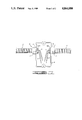
- FIG. 7 is an elevation view of an electrical service system constructed in accordance with the invention.
- the present invention relates to an improved electrical service system in which a terminator fitting 4 is engaged with an electrical outlet box 6 by insertion in a circular opening 7 therethrough, and functions to connect a flexible corrugated conduit 8 to the box.
- This system as illustrated in FIG. 7, further includes insulated electrical conductors 9 which extend through the conduit 8, through the terminator fitting 4 and into the interior of the box 6.
- the terminator fitting 4 in a preferred form, includes a pair of semi-cylindrical collars 10 and 12 which are substantially identical in configuration. In another, less preferred form, the collars may be a single, unitary cylindrical collar element.
- the collars 10 and 12 are preferably constructed of a suitable synthetic resin, such as polyphenyleneoxide base resin or a polyphenylene ether copolymer, and each includes a convex semi-cylindrical external surface 14 and a concave semi-cylindrical internal surface 16.
- each of the semi-cylindrical collars 10 and 12 Carried on the inner surface 16 of each of the semi-cylindrical collars 10 and 12 is at least one radially inwardly projecting arcuate locking rib or ridge 15 which is axially spaced from an arcuate stop flange 19 and is radially dimensioned to engage one of the annular grooves formed around the exterior of a flexible corrugated conduit 8.
- Such conduit 8 is typically used in electrical service systems for containing, and acting as a raceway for, one or more flexible electrical conductors, as illustrated at 9 in FIG. 7.
- the semi-cylindrical collars 10 and 12 are preferably interconnected by a relatively narrow flexible strap 18 which is molded integrally with the two collars, and has its opposite ends connected to the respective collars adjacent the diametric plane which is defined by the relatively broad axial edge portions 17 of each of the two semi-cylindrical collars.
- the collars can be folded out with respect to each other so as to occupy the position illustrated in FIG. 6 of the drawings.
- the two hingedly interconnected collars can be folded together to occupy the positions shown in FIG. 3 of the drawings in which the relatively broad axial edge portions 17 of the collars abut each other along the described diametric plane so as to conjointly form a cylindrical figure of the sort shown in FIGS. 1-3 of the drawings.
- the fitting is formed by an injection molding procedure in which all of the parts of the fitting are integrally formed with all other parts.
- the two collars 10 and 12 need not necessarily be interconnected to each other by a strap, and it is also possible to construct the terminator fitting 4 with a single, integrally molded cylindrical unit replacing the two semi-cylindrical collars.
- Each pair of the semi-cylindrical collars 10 and 12 carries a pair of spaced, axially projecting box-engaging projections.
- the two box-engaging projections carried on the collar 12 are denominated by reference numerals 20 and 22, whereas the box-engaging projections carried on the semi-cylindrical collar 10 are denominated by reference numerals 24 and 26.
- the box-engaging projections 20 and 26 are substantially identical to each other in construction, configuration and function
- the box-engaging projections 22 and 24 are substantially identical to each other in construction, configuration and function.
- Each of the box engaging projections 20-26 is of arcuate, transverse cross-sectional configuration, with each being formed substantially on an arc of a circle. Such arc is preferably slightly less than a quadrant of a circle, or, stated differently, subtends slightly less than 90°. It will be noted that the arcuate box-engaging projection 20 is separated from the box-engaging projection 22 by a circumferential space or gap 28, and that the box-engaging projections 24 and 26 are also separated from each other by a similar circumferential space or gap 30. The projection 20 is also spaced from the projection 24 by an intervening gap 31, and a gap 33 separates the projection 22 from the projection 26.
- each of the arcuate box-engaging projections 20-26 extends in an axial direction from one end, hereinafter termed the axially inner end, of the respective semi-cylindrical collar 10 or 12 upon which it is carried.
- the box-engaging projections 20-26 in collective array form a generally cylindrical figure.
- Each of the arcuate box-engaging projections 20-26 is joined by a web portion 32 to the respective semi-cylindrical collar 10 or 12 upon which it is mounted.
- the web portion 32 has a relatively thin radial dimension, and a relatively narrow circumferential dimension, to thus permit the remaining part of the respective box-engaging projection to flex and pivot radially inwardly as the terminator fitting is pressed into its operative position within the opening of an electrical outlet box as shown in FIG. 4.
- each of the box-engaging projections 20-26 as the outer surface thereof encounters the defining boundary of the circular opening through the box, can undergo radially inward movement by flexure about the hinge constituted by the interconnecting web portion 32.
- the circumferential width of the web portion 32 by which each of the box-engaging projections 20-26 is joined to the respective semi-cylindrical collars 10 or 12 upon which the respective projection is carried is substantially less than the circumferential width of the wedge-shaped free end portion of the respective projection.
- the reduced circumferential width and reduced radial thickness of the web portions 32 facilitate the required flexing movement of the box-engaging projections as the terminator fitting is snapped into the opening of the synthetic resin electrical outlet box 6.
- An important feature of the terminator fitting 4 is the provision of a plurality of blocking flanges which prevent electrical conductors 9 extended through the fitting and into the electrical outlet box 6 from being pulled between the circumferentially-spaced, box-engaging projections 20-26.
- the circumferential spaces 28, 30, 31 and 33 at these locations between the several projections 20-26 have previously presented the problem of permitting insulated electrical conductors 9 passed through the flexible 8 conduit and the fitting 4 and into an electrical outlet box 6 to become jammed in such spaces.
- the conductors 9 then chafe and wear as they undergo any movement so as to sever the insulation and, in extreme instances, to even sever the electrical conductor.
- each of the box-engaging projections 20 and 26 carries an elongated arcuate blocking flange 20b and 26b, respectively.
- the blocking flanges 20b and 26b are molded integrally to the underside of the respective box-engaging projections 20 and 26 near the axial side or edge thereof. In projecting circumferentially away from this axial side or edge, each of the blocking flanges 20b and 26b project across at least a major portion of the intervening circumferential space, and preferably to a location immediately adjacent one side of the other box-engaging projection in the pair carried on the same one of the respective semi-cylindrical collars 10 and 12.
- the blocking flanges 20b and 26b will be perceived to be positioned so that, as the several box-engaging projections 20-26 undergo radially inward movement as they are pressed through the opening in an electrical outlet box 6, the blocking flanges can pass clear of the respective box-engaging projections by extending below the radially inner side thereof with a very slight clearance existing along the radially inner surface of the respective projection 22 or 24 and the adjacent blocking flange.
- box-engaging projections 22 and 24 carry circumferentially extending blocking flanges 22b and 24b, respectively, as best illustrated in FIGS. 3 and 6.
- the blocking flanges 22b and 24b are molded to the underside of the respective box-engaging projection 22 and 24, and adjacent one edge thereof.
- the flanges 22b and 24b project circumferentially from the respective box-engaging projection toward the radially inner surface of the adjacent one of the several box-engaging projections.
- the arcuate box-engaging projections 22 and 24 flex inwardly about the web portions 32 by which these projections are joined to the semi-cylindrical collars 10 and 12 upon which they are carried.
- the blocking flange 22b will move circumferentially along the inner side of the box-engaging projection 26 and will not prevent either the box-engaging projection 26 or the box-engaging projection 22 from flexing radially inwardly.
- the two semi-cylindrical collars 10 and 12, joined by the thin, narrow flexible strap 18, are opened out to the position illustrated in FIG. 6.
- a flexible corrugated conduit 8 having alternating ribs and troughs in the external surface thereof is then placed against one of the semi-cylindrical collars 10 or 12 so that the radially inwardly projecting rib 15 on that collar engages one of the troughs or grooves in the external surface of the conduit.
- the end face of the conduit 8 then bears against the arcuate stop flanges 19.
- the other of the two semi-cylindrical collars 10 and 12 is then folded to a closed position as illustrated in FIG. 3, so that its radially inwardly projecting rib 15 also passes into and engages the groove or trough formed in the external surface of the corrugated conduit 8.
- the terminator fitting 4 is pressed through the opening in the side wall of the box 6 by initially inserting the inner end of the fitting (the end having a radially smaller diameter) into the opening through the box, and forcing the arcuate box-engaging projections 20-26 into the box until they snap engage the box where it surrounds the opening 7 therethrough.
- the terminator fitting 4 is forced inwardly through the opening in the box 6 until the edge of the box wall around the opening 7 comes to rest within, and to occupy, the groove or recess segments defined by the several wedge-shaped end portions 20a-26a of the projections 20-26, the web portions 32 and the two semi-cylindrical collars 10 and 12.
- the several box-engaging projections 20-26 can be flexed radially inwardly, as has been previously described, with the several blocking flanges 20b-26b clearing the adjacent projections, and avoiding any sort of interference or contact with these projections which would preclude the box-engaging projections 20-26 from undergoing the necessary inward flexure to permit the terminator to be snap engaged with the box 6.
- the corrugated conduit 8 can be further screwed into the fitting toward the interior of the flexible outlet box toward the blocking flanges 20b-26b.
- These flanges are positioned radially inwardly with respect to the remaining radially inner surfaces carried on the wedge-shaped free end portions 20a-26a of the arcuate box-engaging projections 20-26.
- the conduit 8 will then ultimately be forced against the several blocking flanges 20b-26b, and will, by such contact, tend to force the box-engaging projections 20-26 radially outwardly slightly so as to more firmly grip the wall of the box 6 between the collars 10 and 12 and the radially thickest portion of the wedge-shaped free end portions 20a-26a end portions. This will firmly lock the terminator fitting in position within the opening in the box, and will also tend to prevent further inward or outward movement of the corrugated conduit.
- the present invention provides an improved terminator fitting for use in connecting a flexible corrugated conduit or pipe to an electrical outlet box.
- the use of the blocking flanges located in the positions described affords a reliable safeguard against electrical conductors becoming jammed into the space between adjacent box-engaging projections forming a part of the fitting, and assures that the fittings will have a longer and more trouble-free operating life.
Abstract
Description
Claims (20)
Priority Applications (1)
| Application Number | Priority Date | Filing Date | Title |
|---|---|---|---|
| US07/056,424 US4864080A (en) | 1987-06-01 | 1987-06-01 | Terminator connector fitting for electrical box and conduit system |
Applications Claiming Priority (1)
| Application Number | Priority Date | Filing Date | Title |
|---|---|---|---|
| US07/056,424 US4864080A (en) | 1987-06-01 | 1987-06-01 | Terminator connector fitting for electrical box and conduit system |
Publications (1)
| Publication Number | Publication Date |
|---|---|
| US4864080A true US4864080A (en) | 1989-09-05 |
Family
ID=22004318
Family Applications (1)
| Application Number | Title | Priority Date | Filing Date |
|---|---|---|---|
| US07/056,424 Expired - Fee Related US4864080A (en) | 1987-06-01 | 1987-06-01 | Terminator connector fitting for electrical box and conduit system |
Country Status (1)
| Country | Link |
|---|---|
| US (1) | US4864080A (en) |
Cited By (40)
| Publication number | Priority date | Publication date | Assignee | Title |
|---|---|---|---|---|
| US5068496A (en) * | 1990-10-31 | 1991-11-26 | Hubbell Incorporated | Snap-in connector |
| US5200209A (en) * | 1989-09-29 | 1993-04-06 | Westinghouse Electric Corp. | Apparatus for producing plastic parts with a resilient projection |
| US5204499A (en) * | 1991-05-03 | 1993-04-20 | Hubbell Incorporated | Snap-in connector with integral spring |
| US5285013A (en) * | 1992-05-19 | 1994-02-08 | Hubbell Incorporated | Non-metallic electrical conduit connector |
| US5422437A (en) * | 1993-04-16 | 1995-06-06 | Hubbell Incorporated | Electrical connector assembly |
| US5519273A (en) * | 1994-09-08 | 1996-05-21 | General Electric Company | Fitting for coupling an electric motor and a motor lead protective conduit |
| US5637021A (en) * | 1994-07-19 | 1997-06-10 | Sanshin Kogyo Kabushiki Kaisha | Control for outboard motor |
| US5777409A (en) * | 1996-02-13 | 1998-07-07 | General Electric Company | Methods and apparatus for coupling an electric motor and a motor lead protective conduit |
| US5915736A (en) * | 1997-07-18 | 1999-06-29 | Thomas & Betts International, Inc. | Integrally formed whip assembly for electrically interconnecting electrical appliances to a power source |
| US6066807A (en) * | 1998-02-20 | 2000-05-23 | Gudgeon; Thomas Alan | Electrical wire and box connector |
| US6108202A (en) * | 1996-07-03 | 2000-08-22 | Sumitomo Wiring Systems, Ltd. | Electric connection box |
| US6395986B1 (en) * | 2000-09-20 | 2002-05-28 | Lyall Assemblies, Inc. | Electrical convoluted tubing with overmolded grommet |
| KR20020092020A (en) * | 2001-06-01 | 2002-12-11 | 이상태 | Electric wiring method of constructed and electric wiring device the same |
| US6495755B2 (en) | 2001-04-26 | 2002-12-17 | Emerson Electric Co. | Self-locking wiring grommet |
| US6521833B1 (en) * | 2001-12-07 | 2003-02-18 | Defreitas Glennon L. | Electrical conduit junction box self-securing insert system |
| US20030190838A1 (en) * | 1999-12-09 | 2003-10-09 | Power Ease, L.L.C. | Integrated electrical receptacle system for outdoor application |
| US20040060723A1 (en) * | 2002-09-26 | 2004-04-01 | Pallapothu Hari S. | Self-sealing grommet assembly |
| US6740812B2 (en) | 2000-09-20 | 2004-05-25 | Dekko Technologies, Inc. | Adaptable electrical tubing system |
| US6794574B2 (en) * | 2000-09-20 | 2004-09-21 | Dekko Technologies, Inc. | Electrical tubing assembly with hermetically sealed ends |
| US20040239109A1 (en) * | 2003-05-29 | 2004-12-02 | Dormont Manufacturing Company | Fluid line connector with intermediate smooth surface |
| US20060005983A1 (en) * | 2004-06-10 | 2006-01-12 | Rizzuto Salvatore A Jr | Slack cable arrangement for underground electric service conduit connected to service boxes on the sides of buildings |
| US7104856B1 (en) * | 2004-06-15 | 2006-09-12 | Brunswick Corporation | Rigging apparatus for an outboard motor |
| US20090183891A1 (en) * | 2008-01-22 | 2009-07-23 | Kramer Jr Wayne A | Adjustable junction box |
| US20100264644A1 (en) * | 2009-04-16 | 2010-10-21 | Royal Group Inc. | Fitting for corrugated conduit |
| US20110001408A1 (en) * | 2009-07-06 | 2011-01-06 | Panduit Corp. | Network Cabinet Fitting System |
| US20110083873A1 (en) * | 2009-10-14 | 2011-04-14 | Panduit Corp. | Network Cabinet Fitting System |
| US20120014048A1 (en) * | 2010-07-14 | 2012-01-19 | Robert Bosch Gmbh | Cable Kink Protection Unit and Method for Producing Same |
| USD663697S1 (en) | 2009-06-03 | 2012-07-17 | Royal Group Inc. | Conduit fitting ring |
| WO2013163315A1 (en) * | 2012-04-27 | 2013-10-31 | Dominion Resources, Inc. | Conduit clamp |
| US8669471B2 (en) | 2010-09-14 | 2014-03-11 | Southwire Company | Electrical accessories and associated methods of use and manufacture |
| US8789256B2 (en) | 2010-09-14 | 2014-07-29 | Southwire Company, Llc | Folded electrical junction boxes and associated methods of use and manufacture |
| US8834216B1 (en) | 2013-01-31 | 2014-09-16 | Brp Us Inc. | Water deflector for a marine outboard engine |
| US8858280B1 (en) | 2010-10-29 | 2014-10-14 | Brp Us Inc. | Marine engine rigging system |
| US9496694B1 (en) | 2015-06-12 | 2016-11-15 | Arlington Industries, Inc. | Easy insertion electrical connector |
| CN106532598A (en) * | 2017-01-18 | 2017-03-22 | 广德亚捷实业有限公司 | Metal insulating corrugated connecting pipe |
| US9819167B2 (en) | 2009-09-04 | 2017-11-14 | Cantex, Inc. | Electrical accessories and associated methods of use and manufacture |
| US20180090858A1 (en) * | 2016-09-28 | 2018-03-29 | Panasonic Ecology Systems Guangdong Co., Ltd. | Wire detachment-preventing structure |
| US10431970B1 (en) * | 2015-01-22 | 2019-10-01 | Arlington Industries, Inc. | Electrical insider fitting for internal connection of flexible metal conduit to an electrical box |
| US10923894B1 (en) | 2017-08-23 | 2021-02-16 | Arlington Industries, Inc. | Push-in electrical connector insertable from the inside or outside of a junction box |
| EP3062137B1 (en) * | 2015-02-24 | 2023-06-07 | Prysmian S.p.A. | Method of connecting an optical fiber cable to a closure box, and a connector and assembly therefore |
Citations (9)
| Publication number | Priority date | Publication date | Assignee | Title |
|---|---|---|---|---|
| US2420826A (en) * | 1944-03-24 | 1947-05-20 | Louis J Irrgang | Strain relief for electrical conductors |
| US2505312A (en) * | 1946-12-16 | 1950-04-25 | John J Wagner | Cable armor connector |
| US2952730A (en) * | 1957-03-06 | 1960-09-13 | Albert L Simonds | Strain relief grommet |
| US4248459A (en) * | 1978-02-06 | 1981-02-03 | Indian Head Inc. | Flexible conduit system |
| US4302035A (en) * | 1979-03-12 | 1981-11-24 | Ochwat Richard S | One piece electrical connector |
| US4494779A (en) * | 1982-07-14 | 1985-01-22 | Thyssen-Bornemisza Inc. | Connector fitting for electrical box |
| US4578528A (en) * | 1983-07-29 | 1986-03-25 | Thyssen-Bornemisza, Inc., (Tbg Inc.) | Electrical outlet box and method of manufacturing same |
| US4616105A (en) * | 1984-10-26 | 1986-10-07 | Tbg Inc. | Adapter fitting for connecting flexible conduit to electrical outlet boxes |
| US4711472A (en) * | 1986-09-02 | 1987-12-08 | Hubbell Incorporated | Connector for non-metallic conduit |
-
1987
- 1987-06-01 US US07/056,424 patent/US4864080A/en not_active Expired - Fee Related
Patent Citations (9)
| Publication number | Priority date | Publication date | Assignee | Title |
|---|---|---|---|---|
| US2420826A (en) * | 1944-03-24 | 1947-05-20 | Louis J Irrgang | Strain relief for electrical conductors |
| US2505312A (en) * | 1946-12-16 | 1950-04-25 | John J Wagner | Cable armor connector |
| US2952730A (en) * | 1957-03-06 | 1960-09-13 | Albert L Simonds | Strain relief grommet |
| US4248459A (en) * | 1978-02-06 | 1981-02-03 | Indian Head Inc. | Flexible conduit system |
| US4302035A (en) * | 1979-03-12 | 1981-11-24 | Ochwat Richard S | One piece electrical connector |
| US4494779A (en) * | 1982-07-14 | 1985-01-22 | Thyssen-Bornemisza Inc. | Connector fitting for electrical box |
| US4578528A (en) * | 1983-07-29 | 1986-03-25 | Thyssen-Bornemisza, Inc., (Tbg Inc.) | Electrical outlet box and method of manufacturing same |
| US4616105A (en) * | 1984-10-26 | 1986-10-07 | Tbg Inc. | Adapter fitting for connecting flexible conduit to electrical outlet boxes |
| US4711472A (en) * | 1986-09-02 | 1987-12-08 | Hubbell Incorporated | Connector for non-metallic conduit |
Cited By (48)
| Publication number | Priority date | Publication date | Assignee | Title |
|---|---|---|---|---|
| US5200209A (en) * | 1989-09-29 | 1993-04-06 | Westinghouse Electric Corp. | Apparatus for producing plastic parts with a resilient projection |
| US5068496A (en) * | 1990-10-31 | 1991-11-26 | Hubbell Incorporated | Snap-in connector |
| US5204499A (en) * | 1991-05-03 | 1993-04-20 | Hubbell Incorporated | Snap-in connector with integral spring |
| US5285013A (en) * | 1992-05-19 | 1994-02-08 | Hubbell Incorporated | Non-metallic electrical conduit connector |
| US5422437A (en) * | 1993-04-16 | 1995-06-06 | Hubbell Incorporated | Electrical connector assembly |
| US5637021A (en) * | 1994-07-19 | 1997-06-10 | Sanshin Kogyo Kabushiki Kaisha | Control for outboard motor |
| US5519273A (en) * | 1994-09-08 | 1996-05-21 | General Electric Company | Fitting for coupling an electric motor and a motor lead protective conduit |
| US5777409A (en) * | 1996-02-13 | 1998-07-07 | General Electric Company | Methods and apparatus for coupling an electric motor and a motor lead protective conduit |
| US6108202A (en) * | 1996-07-03 | 2000-08-22 | Sumitomo Wiring Systems, Ltd. | Electric connection box |
| US5915736A (en) * | 1997-07-18 | 1999-06-29 | Thomas & Betts International, Inc. | Integrally formed whip assembly for electrically interconnecting electrical appliances to a power source |
| US6066807A (en) * | 1998-02-20 | 2000-05-23 | Gudgeon; Thomas Alan | Electrical wire and box connector |
| US6881094B2 (en) | 1999-12-09 | 2005-04-19 | Power Ease, L.L.C. | Integrated electrical receptacle system for outdoor application |
| US20030190838A1 (en) * | 1999-12-09 | 2003-10-09 | Power Ease, L.L.C. | Integrated electrical receptacle system for outdoor application |
| US6395986B1 (en) * | 2000-09-20 | 2002-05-28 | Lyall Assemblies, Inc. | Electrical convoluted tubing with overmolded grommet |
| US6740812B2 (en) | 2000-09-20 | 2004-05-25 | Dekko Technologies, Inc. | Adaptable electrical tubing system |
| US6794574B2 (en) * | 2000-09-20 | 2004-09-21 | Dekko Technologies, Inc. | Electrical tubing assembly with hermetically sealed ends |
| US6495755B2 (en) | 2001-04-26 | 2002-12-17 | Emerson Electric Co. | Self-locking wiring grommet |
| KR20020092020A (en) * | 2001-06-01 | 2002-12-11 | 이상태 | Electric wiring method of constructed and electric wiring device the same |
| US6521833B1 (en) * | 2001-12-07 | 2003-02-18 | Defreitas Glennon L. | Electrical conduit junction box self-securing insert system |
| US20040060723A1 (en) * | 2002-09-26 | 2004-04-01 | Pallapothu Hari S. | Self-sealing grommet assembly |
| US6768058B2 (en) * | 2002-09-26 | 2004-07-27 | Kirkhill-Ta Co. | Self-sealing grommet assembly |
| US7198304B2 (en) * | 2003-05-29 | 2007-04-03 | Dormont Manufacturing Company | Fluid line connector with intermediate smooth surface |
| US20040239109A1 (en) * | 2003-05-29 | 2004-12-02 | Dormont Manufacturing Company | Fluid line connector with intermediate smooth surface |
| US20060005983A1 (en) * | 2004-06-10 | 2006-01-12 | Rizzuto Salvatore A Jr | Slack cable arrangement for underground electric service conduit connected to service boxes on the sides of buildings |
| US7394023B2 (en) | 2004-06-10 | 2008-07-01 | Rizzuto Jr Salvatore A | Slack cable arrangement for underground electric service conduit connected to service boxes on the sides of buildings |
| US7104856B1 (en) * | 2004-06-15 | 2006-09-12 | Brunswick Corporation | Rigging apparatus for an outboard motor |
| US20090183891A1 (en) * | 2008-01-22 | 2009-07-23 | Kramer Jr Wayne A | Adjustable junction box |
| US20100264644A1 (en) * | 2009-04-16 | 2010-10-21 | Royal Group Inc. | Fitting for corrugated conduit |
| US8056938B2 (en) | 2009-04-16 | 2011-11-15 | Royal Group Inc. | Fitting for corrugated conduit |
| USD663697S1 (en) | 2009-06-03 | 2012-07-17 | Royal Group Inc. | Conduit fitting ring |
| US20110001408A1 (en) * | 2009-07-06 | 2011-01-06 | Panduit Corp. | Network Cabinet Fitting System |
| US9819167B2 (en) | 2009-09-04 | 2017-11-14 | Cantex, Inc. | Electrical accessories and associated methods of use and manufacture |
| US20110083873A1 (en) * | 2009-10-14 | 2011-04-14 | Panduit Corp. | Network Cabinet Fitting System |
| US8791367B2 (en) | 2009-10-14 | 2014-07-29 | Panduit Corp. | Network cabinet fitting system |
| US8586879B2 (en) * | 2010-07-14 | 2013-11-19 | Robert Bosch Gmbh | Cable kink protection unit and method for producing same |
| US20120014048A1 (en) * | 2010-07-14 | 2012-01-19 | Robert Bosch Gmbh | Cable Kink Protection Unit and Method for Producing Same |
| US8669471B2 (en) | 2010-09-14 | 2014-03-11 | Southwire Company | Electrical accessories and associated methods of use and manufacture |
| US8789256B2 (en) | 2010-09-14 | 2014-07-29 | Southwire Company, Llc | Folded electrical junction boxes and associated methods of use and manufacture |
| US8858280B1 (en) | 2010-10-29 | 2014-10-14 | Brp Us Inc. | Marine engine rigging system |
| WO2013163315A1 (en) * | 2012-04-27 | 2013-10-31 | Dominion Resources, Inc. | Conduit clamp |
| US8834216B1 (en) | 2013-01-31 | 2014-09-16 | Brp Us Inc. | Water deflector for a marine outboard engine |
| US10431970B1 (en) * | 2015-01-22 | 2019-10-01 | Arlington Industries, Inc. | Electrical insider fitting for internal connection of flexible metal conduit to an electrical box |
| EP3062137B1 (en) * | 2015-02-24 | 2023-06-07 | Prysmian S.p.A. | Method of connecting an optical fiber cable to a closure box, and a connector and assembly therefore |
| US9496694B1 (en) | 2015-06-12 | 2016-11-15 | Arlington Industries, Inc. | Easy insertion electrical connector |
| US9991613B2 (en) * | 2016-09-28 | 2018-06-05 | Panasonic Ecology Systems Guangdong Co., Ltd. | Wire detachment-preventing structure |
| US20180090858A1 (en) * | 2016-09-28 | 2018-03-29 | Panasonic Ecology Systems Guangdong Co., Ltd. | Wire detachment-preventing structure |
| CN106532598A (en) * | 2017-01-18 | 2017-03-22 | 广德亚捷实业有限公司 | Metal insulating corrugated connecting pipe |
| US10923894B1 (en) | 2017-08-23 | 2021-02-16 | Arlington Industries, Inc. | Push-in electrical connector insertable from the inside or outside of a junction box |
Similar Documents
| Publication | Publication Date | Title |
|---|---|---|
| US4864080A (en) | Terminator connector fitting for electrical box and conduit system | |
| US4711472A (en) | Connector for non-metallic conduit | |
| US4494779A (en) | Connector fitting for electrical box | |
| US6872886B2 (en) | Electrical cable connector | |
| US6737584B2 (en) | Electrical cable connector | |
| US5422437A (en) | Electrical connector assembly | |
| US5204499A (en) | Snap-in connector with integral spring | |
| US4575133A (en) | Conduit connector | |
| US6034326A (en) | Conduit connector assembly spring clip having scalloped shaped conduit gripping end | |
| US6555750B2 (en) | Electrical cable connector | |
| US4621166A (en) | Adjustable line covering electrical connector | |
| US4989905A (en) | Fitting for corrugated tubing | |
| EP1993179B1 (en) | Cable grommet designed to facilitate cable insertion and hinder removal | |
| US7901222B2 (en) | Electrical metal clad connectors and methods of use | |
| US4711974A (en) | Adapter fitting for connecting flexible conduit to electrical outlet boxes | |
| US3483310A (en) | Connector insulator | |
| US4616105A (en) | Adapter fitting for connecting flexible conduit to electrical outlet boxes | |
| US5043536A (en) | Rotation-limiting knockout configuration | |
| US5688132A (en) | Plug in raceway with socketless receptacle | |
| US10483735B1 (en) | Ninety degree snap fit electrical fitting for connection of electrical cables to an electrical box | |
| US4578528A (en) | Electrical outlet box and method of manufacturing same | |
| US5908180A (en) | Symmetrical cable bracketing and strain relieving mechanism and method | |
| US6595284B2 (en) | Wire guard device for wells | |
| US6472596B1 (en) | Coupling mechanism for an electrical fitting including energy absorbing self-returning snaps | |
| US20040251682A1 (en) | Range taking snap-in connector |
Legal Events
| Date | Code | Title | Description |
|---|---|---|---|
| AS | Assignment |
Owner name: CARLON COMPANY, THE 25701 SCIENCE PARK DR. CLEVELA Free format text: ASSIGNMENT OF ASSIGNORS INTEREST.;ASSIGNOR:FOCHLER, HELMUT P.;REEL/FRAME:004738/0105 Effective date: 19870526 Owner name: CARLON COMAPANY, THE 25701 SCIENCE PARK DR.CLEVELA Free format text: ASSIGNMENT OF ASSIGNORS INTEREST.;ASSIGNORS:URKEWICH, JOSEPH;SAUERBREI, DARYL J.;REEL/FRAME:004738/0107 Effective date: 19870522 |
|
| AS | Assignment |
Owner name: GENERAL ELECTRIC CAPITAL CORPORATION Free format text: SECURITY INTEREST;ASSIGNOR:LAMSON & SESSIONS CO., THE;REEL/FRAME:006016/0227 Effective date: 19920213 |
|
| REMI | Maintenance fee reminder mailed | ||
| LAPS | Lapse for failure to pay maintenance fees | ||
| FP | Lapsed due to failure to pay maintenance fee |
Effective date: 19930905 |
|
| STCH | Information on status: patent discontinuation |
Free format text: PATENT EXPIRED DUE TO NONPAYMENT OF MAINTENANCE FEES UNDER 37 CFR 1.362 |