US4863243A - Mount for an optical element including a holder with a generally semicylindrical surface - Google Patents
Mount for an optical element including a holder with a generally semicylindrical surface Download PDFInfo
- Publication number
- US4863243A US4863243A US07/191,679 US19167988A US4863243A US 4863243 A US4863243 A US 4863243A US 19167988 A US19167988 A US 19167988A US 4863243 A US4863243 A US 4863243A
- Authority
- US
- United States
- Prior art keywords
- mount
- holder
- mirror
- optical
- optical axis
- Prior art date
- Legal status (The legal status is an assumption and is not a legal conclusion. Google has not performed a legal analysis and makes no representation as to the accuracy of the status listed.)
- Expired - Fee Related
Links
- 230000003287 optical effect Effects 0.000 title claims abstract description 40
- 230000035939 shock Effects 0.000 description 2
- 230000000694 effects Effects 0.000 description 1
- 230000001939 inductive effect Effects 0.000 description 1
- 238000003780 insertion Methods 0.000 description 1
- 230000037431 insertion Effects 0.000 description 1
- 238000012986 modification Methods 0.000 description 1
- 230000004048 modification Effects 0.000 description 1
Images
Classifications
-
- G—PHYSICS
- G02—OPTICS
- G02B—OPTICAL ELEMENTS, SYSTEMS OR APPARATUS
- G02B7/00—Mountings, adjusting means, or light-tight connections, for optical elements
- G02B7/18—Mountings, adjusting means, or light-tight connections, for optical elements for prisms; for mirrors
- G02B7/182—Mountings, adjusting means, or light-tight connections, for optical elements for prisms; for mirrors for mirrors
- G02B7/1822—Mountings, adjusting means, or light-tight connections, for optical elements for prisms; for mirrors for mirrors comprising means for aligning the optical axis
- G02B7/1824—Manual alignment
- G02B7/1825—Manual alignment made by screws, e.g. for laser mirrors
Definitions
- the present invention relates to a mount for an optical element, and more particularly, to such a mount which can be adjusted to accurately position an optical element in optical apparatus.
- Optical elements must be very accurately positioned in certain types of apparatus such as apparatus using lasers as a light source.
- Mounts for the optical elements must be adjustable in order to position the element relative to a laser beam and to compensate for changes in the optical system.
- the optical elements must also be able to withstand shock and vibration without moving from an adjusted position, and thus, the mounts must include means for locking the optical elements in an adjusted position without inducing distortion or strain in the optical element.
- One of the main problems in prior-art mounts for optical elements is that the mounts cannot be easily adjusted to a precise position.
- a further problem with known mounts is that they cannot be locked after adjustment without changing the adjusted position.
- U.S. Pat. No. 4,563,058 there is shown a mount for a dichroic mirror in a transducer for an optical signal recorder.
- the dichroic mirror includes a hemispherical portion and a planar optical surface.
- the hemispherical portion of the mirror is received in a hemispherical socket in the mount, and an aperture plate is placed over a portion of the optical surface of the mirror to secure the mirror in the socket.
- the aperture plate is held in position by four screws.
- the mirror can be adjusted about orthogonal axes by adjusting the screws holding the aperture plate.
- a problem with the mount disclosed in this patent is that it is difficult to maintain an adjustment made about one of the axes while an adjustment is being made about the other axis.
- a mount for an optical element the mount being adjustable to position the element relative to an optical axis, the element being adapted to receive an input light beam along the axis and to direct an output light beam away from the element
- the mount comprising: a holder for the optical element; first means for supporting the holder for rotation about the optical axis, the holder upon rotation moving the output beam along a first generally straight line; and second means for supporting the first means for rotation about a second axis generally perpendicular to the optical axis, the first means upon rotation moving the output beam along a second generally straight line perpendicular to the first straight line whereby the output beam can be positioned within the confines of a rectangular cone by rotation of the holder and the first means.
- a mount is adapted to support a circular mirror, and the angular position of the mirror can be adjusted in two rotational degrees of freedom.
- the circular mirror is mounted in a holder which is supported in a plate for pivotal movement about the optical axis.
- the plate is supported in a base for pivotal movement about a generally vertical axis. Both the holder and the plate can be independently adjusted to move the mirror to a desired position, and means are provided for locking the holder and the plate in adjusted positions.
- One advantage of the present invention is that a first adjustment can be made in one rotational degree of freedom and the mount can be locked in the adjusted position, and then, a second adjustment can be made in another rotational degree of freedom without in any way changing the angular position of the first adjustment.
- the optical element In each rotational degree of freedom, the optical element is adjusted such that an output beam from the element is moved along a generally straight line.
- Another advantage of the present invention is that an optical element can be adjusted around a pivot point on a surface thereof regardless of the thickness of the element; this permits the adjustment of the angle at which a beam is reflected from the element without changing the position of the point of reflection.
- the disclosed mount can be used in a variety of applications due to its compact design, and the mount is very resistant to vibration and shock.
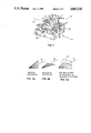
- FIG. 1 is a perspective view of the mount of the present invention
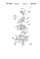
- FIG. 2 is an exploded perspective view of the mount shown in FIG. 1;
- FIGS. 3A-3C are diagrammatic illustrations of the range of adjusted positions of a beam which can be achieved in the disclosed mount.
- the mount of the present invention is described herein as being for a mirror. It will be apparent, however, that the mount could be used for other optical elements, for example, a prism.
- the mount of the present invention is useful in optical apparatus, such as a laser printer, where very high precision is required. References herein to terms such as “up,” “down,” “vertical,” and “horizontal,” refer to the present invention in the orientation shown in FIG. 1.
- FIGS. 1 and 2 there is shown a mount 10 for a circular mirror 12 which is supported therein along an optical axis 11 of, for example, an input beam of light.
- mirror 12 can be adjusted to determine the optical axis 15 of a beam reflected from mirror 12.
- Mirror 12 is supported in a holder 14 such that an operative surface 17 of the mirror 12 is disposed at an angle of 45° to axis 11, and the mirror 12 is held in holder 14 by spring-loaded screws 16 of a well-known type.
- holder 14 is separable into a top portion 18 and a bottom portion 20 to permit easy insertion of mirror 12. Portions 18 and 20 are held together by fasteners (not shown).
- Bottom portion 20 of holder 14 has a generally semicylindrical surface 28 which is shaped to cooperate with cylindrical bearing surfaces 22 and 24 in a plate 30.
- Holder 14 is adapted to pivot in plate 30 to provide a vertical deflection adjustment of mirror 12 and thereby locate the axis 15 of an output beam along a generally vertical line,as shown diagrammatically in FIGS. 3A and 3C.
- Holder 14 is pivotal about optical axis 11, the directions of pivotal movement being indicated by the arrows 25.
- Holder 14 is constrained from movement in an axial direction by a pin 32 on plate 30 which is received in a groove (not shown) in surface 28.
- holder 14 In the assembly of mount 10, holder 14 is inserted in plate 30, and an adjustment bar 29 having shoulders 36 thereon is fastened to bottom portion 20 of holder 14.
- Holder 14 can be adjusted to a desired angular position by means of set screws 34 which are threaded in plate 30 and abut against shoulders 36 of adjustment bar 29. It will be seen that angular adjustment of holder 14 can be effected by backing off one of the screws 34 a certain distance while the other of the screws 34 is advanced an equal distance.
- a locking screw 68 is provided to lock holder 14 in an adjusted position.
- Plate 30 is received in a base 40 and is supported in a vertical direction by surfaces 44 and a raised portion (not shown) of surface 46 on the base 40.
- Cylindrical end portions 48 and 50 on plate 30 are adapted to cooperate, respectively, with cylindrical surfaces 52 and 54 on base 40 to provide for pivotal movement of plate 30 about a vertical axis (not shown).
- Pivotal movement of plate 30 about a vertical axis (indicated by arrows 53 in FIG. 2) provides a horizontal deflection adjustment of mirror 12 to move the axis 15 of an output beam along a generally horizontal line, as shown diagrammatically in FIGS. 3B and 3C.
- Angular movement of plate 30 is effected by set screws 60 which are threaded in base 40 and abut against surfaces 62 and 64 on plate 30.
- One of the screws 60 is advanced a given amount while the other is backed off the same amount to effect movement of plate 30 to an adjusted position.
- a locking screw 66 is tightened against surface 48 to lock plate 30 in position.
- mount 10 In the use of mount 10 in optical apparatus (not shown), the mount is secured in the apparatus by means of fasteners (not shown) inserted in holes 70.
- Mount 10 is located so that mirror 12 will receive a light beam along optical axis 11. Both vertical and horizontal deflection adjustments are then made, as described above, to precisely locate axis 15 of a beam reflected from mirror 12.
- holder 14 is rotated by means of screws 34 to make the horizontal deflection adjustment, and the holder 14 is locked in the adjusted position by screw 68.
- plate 30 In a second step, plate 30 is positioned by means of screws 60 to make the horizontal deflection adjustment, and the plate 30 is locked in the adjusted position by screw 66.
- the two adjustments position a reflected beam, with very high resolution, within the confines of a square cone 70 which is shown diagrammatically in FIG. 3C.
Landscapes
- Physics & Mathematics (AREA)
- General Physics & Mathematics (AREA)
- Optics & Photonics (AREA)
- Mounting And Adjusting Of Optical Elements (AREA)
Abstract
Description
Claims (5)
Priority Applications (1)
| Application Number | Priority Date | Filing Date | Title |
|---|---|---|---|
| US07/191,679 US4863243A (en) | 1988-05-09 | 1988-05-09 | Mount for an optical element including a holder with a generally semicylindrical surface |
Applications Claiming Priority (1)
| Application Number | Priority Date | Filing Date | Title |
|---|---|---|---|
| US07/191,679 US4863243A (en) | 1988-05-09 | 1988-05-09 | Mount for an optical element including a holder with a generally semicylindrical surface |
Publications (1)
| Publication Number | Publication Date |
|---|---|
| US4863243A true US4863243A (en) | 1989-09-05 |
Family
ID=22706485
Family Applications (1)
| Application Number | Title | Priority Date | Filing Date |
|---|---|---|---|
| US07/191,679 Expired - Fee Related US4863243A (en) | 1988-05-09 | 1988-05-09 | Mount for an optical element including a holder with a generally semicylindrical surface |
Country Status (1)
| Country | Link |
|---|---|
| US (1) | US4863243A (en) |
Cited By (13)
| Publication number | Priority date | Publication date | Assignee | Title |
|---|---|---|---|---|
| US4976528A (en) * | 1989-02-17 | 1990-12-11 | Joseph Cuda | Laser manipulator |
| US5195707A (en) * | 1992-05-12 | 1993-03-23 | Ignatuk Wayne R | Optic positioning device |
| US5626424A (en) * | 1994-07-21 | 1997-05-06 | Raytek Subsidiary, Inc. | Dual light source aiming mechanism and improved actuation system for hand-held temperature measuring unit |
| US6061190A (en) * | 1999-03-11 | 2000-05-09 | Optics For Research | Devices for holding optical components at fixed positions |
| EP0974858A3 (en) * | 1998-07-22 | 2000-11-08 | Trumpf GmbH & Co | Mounting for a mirror for guiding a laser beam at a laser processing machine and mirror mount as part of such a mounting |
| US6384993B1 (en) | 1999-11-03 | 2002-05-07 | Itt Manufacturing Enterprises, Inc. | Precisely adjustable optical device having vibration and temperature stability |
| US6515810B1 (en) * | 2000-10-28 | 2003-02-04 | Reinshaw Plc | Mounting module for an optical element |
| US6603611B1 (en) | 2001-11-06 | 2003-08-05 | Itt Manufacturing Enterprises, Inc. | Mount for ultra-high performance of optical components under thermal and vibrational distortion conditions |
| EP1932044A4 (en) * | 2005-10-06 | 2011-01-19 | Ellex Medical Pty Ltd | Gimbal mount |
| AU2016200298B2 (en) * | 2011-01-10 | 2018-01-18 | Illumina, Inc. | Systems, methods, and apparatuses to image a sample for biological or chemical analysis |
| US10220386B2 (en) | 2011-01-10 | 2019-03-05 | Illumina, Inc. | Systems, methods, and apparatuses to image a sample for biological or chemical analysis |
| US11246430B2 (en) | 2020-02-10 | 2022-02-15 | Photon Valley, Inc. | Kinematic mirror mount and adjustment system |
| US11347025B2 (en) * | 2020-02-10 | 2022-05-31 | Photon Valley, Inc. | Kinematic mount |
Citations (11)
| Publication number | Priority date | Publication date | Assignee | Title |
|---|---|---|---|---|
| US3357268A (en) * | 1964-05-01 | 1967-12-12 | Gen Dynamics Corp | Optical cell |
| US3478608A (en) * | 1966-06-23 | 1969-11-18 | Electro Optics Associates | Aligning and mounting mechanism device |
| US3588025A (en) * | 1970-01-16 | 1971-06-28 | Jerome Gersman | Optically alignable bench mark |
| US3642353A (en) * | 1970-10-02 | 1972-02-15 | Lasermation Inc | Adjustable mirror assembly |
| US4171902A (en) * | 1976-02-19 | 1979-10-23 | Canon Kabushiki Kaisha | Information processing system having an optic axis adjusting mirror device |
| US4298248A (en) * | 1980-05-16 | 1981-11-03 | The United States Of America As Represented By The Secretary Of The Navy | Pivotal support with independent adjusting elements and locking means |
| US4560244A (en) * | 1984-06-25 | 1985-12-24 | Solavolt International | Apparatus and method for redirecting an incident beam |
| US4563058A (en) * | 1984-06-28 | 1986-01-07 | International Business Machines Corporation | Optical signal recorder employing a transducer having an adjustable dichroic mirror |
| US4655548A (en) * | 1984-10-22 | 1987-04-07 | Grumman Aerospace Corporation | Multi-degree of freedom mount |
| SU1315922A1 (en) * | 1985-12-16 | 1987-06-07 | Предприятие П/Я Р-6495 | Holder for aligning lenses |
| US4705369A (en) * | 1986-03-21 | 1987-11-10 | The United States Of America As Represented By The United States Department Of Energy | Mirror mount |
-
1988
- 1988-05-09 US US07/191,679 patent/US4863243A/en not_active Expired - Fee Related
Patent Citations (11)
| Publication number | Priority date | Publication date | Assignee | Title |
|---|---|---|---|---|
| US3357268A (en) * | 1964-05-01 | 1967-12-12 | Gen Dynamics Corp | Optical cell |
| US3478608A (en) * | 1966-06-23 | 1969-11-18 | Electro Optics Associates | Aligning and mounting mechanism device |
| US3588025A (en) * | 1970-01-16 | 1971-06-28 | Jerome Gersman | Optically alignable bench mark |
| US3642353A (en) * | 1970-10-02 | 1972-02-15 | Lasermation Inc | Adjustable mirror assembly |
| US4171902A (en) * | 1976-02-19 | 1979-10-23 | Canon Kabushiki Kaisha | Information processing system having an optic axis adjusting mirror device |
| US4298248A (en) * | 1980-05-16 | 1981-11-03 | The United States Of America As Represented By The Secretary Of The Navy | Pivotal support with independent adjusting elements and locking means |
| US4560244A (en) * | 1984-06-25 | 1985-12-24 | Solavolt International | Apparatus and method for redirecting an incident beam |
| US4563058A (en) * | 1984-06-28 | 1986-01-07 | International Business Machines Corporation | Optical signal recorder employing a transducer having an adjustable dichroic mirror |
| US4655548A (en) * | 1984-10-22 | 1987-04-07 | Grumman Aerospace Corporation | Multi-degree of freedom mount |
| SU1315922A1 (en) * | 1985-12-16 | 1987-06-07 | Предприятие П/Я Р-6495 | Holder for aligning lenses |
| US4705369A (en) * | 1986-03-21 | 1987-11-10 | The United States Of America As Represented By The United States Department Of Energy | Mirror mount |
Cited By (21)
| Publication number | Priority date | Publication date | Assignee | Title |
|---|---|---|---|---|
| US4976528A (en) * | 1989-02-17 | 1990-12-11 | Joseph Cuda | Laser manipulator |
| US5195707A (en) * | 1992-05-12 | 1993-03-23 | Ignatuk Wayne R | Optic positioning device |
| US5626424A (en) * | 1994-07-21 | 1997-05-06 | Raytek Subsidiary, Inc. | Dual light source aiming mechanism and improved actuation system for hand-held temperature measuring unit |
| EP0974858A3 (en) * | 1998-07-22 | 2000-11-08 | Trumpf GmbH & Co | Mounting for a mirror for guiding a laser beam at a laser processing machine and mirror mount as part of such a mounting |
| US6061190A (en) * | 1999-03-11 | 2000-05-09 | Optics For Research | Devices for holding optical components at fixed positions |
| US6384993B1 (en) | 1999-11-03 | 2002-05-07 | Itt Manufacturing Enterprises, Inc. | Precisely adjustable optical device having vibration and temperature stability |
| US6519101B2 (en) | 1999-11-03 | 2003-02-11 | Itt Manufacturing Enterprises, Inc. | Precisely adjustable optical device having vibration and temperature stability |
| US6515810B1 (en) * | 2000-10-28 | 2003-02-04 | Reinshaw Plc | Mounting module for an optical element |
| US6603611B1 (en) | 2001-11-06 | 2003-08-05 | Itt Manufacturing Enterprises, Inc. | Mount for ultra-high performance of optical components under thermal and vibrational distortion conditions |
| EP1932044A4 (en) * | 2005-10-06 | 2011-01-19 | Ellex Medical Pty Ltd | Gimbal mount |
| AU2016200298B2 (en) * | 2011-01-10 | 2018-01-18 | Illumina, Inc. | Systems, methods, and apparatuses to image a sample for biological or chemical analysis |
| US10220386B2 (en) | 2011-01-10 | 2019-03-05 | Illumina, Inc. | Systems, methods, and apparatuses to image a sample for biological or chemical analysis |
| US11117130B2 (en) | 2011-01-10 | 2021-09-14 | Illumina, Inc. | Systems, methods, and apparatuses to image a sample for biological or chemical analysis |
| US11559805B2 (en) | 2011-01-10 | 2023-01-24 | Illumina, Inc. | Systems, methods, and apparatuses to image a sample for biological or chemical analysis |
| US11697116B2 (en) | 2011-01-10 | 2023-07-11 | Illumina, Inc. | Systems, methods, and apparatuses to image a sample for biological or chemical analysis |
| US11938479B2 (en) | 2011-01-10 | 2024-03-26 | Illumina, Inc. | Systems, methods, and apparatuses to image a sample for biological or chemical analysis |
| US12151241B2 (en) | 2011-01-10 | 2024-11-26 | Illumina, Inc. | Systems, methods, and apparatuses to image a sample for biological or chemical analysis |
| US12502669B2 (en) | 2011-01-10 | 2025-12-23 | Illumina, Inc. | Systems, methods, and apparatuses to image a sample for biological or chemical analysis |
| US12558687B2 (en) | 2011-01-10 | 2026-02-24 | Illumina, Inc. | Systems, methods, and apparatuses to image a sample for biological or chemical analysis |
| US11246430B2 (en) | 2020-02-10 | 2022-02-15 | Photon Valley, Inc. | Kinematic mirror mount and adjustment system |
| US11347025B2 (en) * | 2020-02-10 | 2022-05-31 | Photon Valley, Inc. | Kinematic mount |
Similar Documents
| Publication | Publication Date | Title |
|---|---|---|
| US4863243A (en) | Mount for an optical element including a holder with a generally semicylindrical surface | |
| JP3184825B2 (en) | Apparatus and method for accurately adjusting the angular position of an optical device | |
| US5140470A (en) | Optical mounting apparatus | |
| US5220460A (en) | Adjustable mount for cylindrical lens with torque applied directly to lens | |
| US6614601B2 (en) | Gimballed optical mount | |
| EP1015930B1 (en) | Method and system for mounting optical elements | |
| US3642353A (en) | Adjustable mirror assembly | |
| US3814365A (en) | Adjustable mirror mount | |
| JPH06502803A (en) | Laser alignment and control device | |
| US4298248A (en) | Pivotal support with independent adjusting elements and locking means | |
| US5195707A (en) | Optic positioning device | |
| US4880301A (en) | Mount for an optical element | |
| US5210648A (en) | Adjustable mount for cylindrical lens with independent rotational feature | |
| US4302885A (en) | North finder with optical transfer provision | |
| US6323903B1 (en) | Three axis camera mount | |
| US6296362B1 (en) | Vibration hardened mirror mount with alignment friendly locking | |
| US4764010A (en) | Method for aligning the axis of a second bracket relative to the axis of a first bracket on a testing or processing machine | |
| US5798879A (en) | Stress-free, adjustable optical support | |
| US5245478A (en) | Mount for Berek compensator | |
| US5214441A (en) | Method and apparatus for alignment of scan line optics with target medium using external adjusting members | |
| JP3214924B2 (en) | Printer and optical system positioning method | |
| US5105297A (en) | Mount for an optical element | |
| USH396H (en) | Prism holder | |
| US6550925B1 (en) | Mirror support | |
| US4968122A (en) | Galvanometer gimbal mount |
Legal Events
| Date | Code | Title | Description |
|---|---|---|---|
| FEPP | Fee payment procedure |
Free format text: PAYOR NUMBER ASSIGNED (ORIGINAL EVENT CODE: ASPN); ENTITY STATUS OF PATENT OWNER: LARGE ENTITY |
|
| FEPP | Fee payment procedure |
Free format text: PAYOR NUMBER ASSIGNED (ORIGINAL EVENT CODE: ASPN); ENTITY STATUS OF PATENT OWNER: LARGE ENTITY Free format text: PAYER NUMBER DE-ASSIGNED (ORIGINAL EVENT CODE: RMPN); ENTITY STATUS OF PATENT OWNER: LARGE ENTITY |
|
| AS | Assignment |
Owner name: EASTMAN KODAK COMPANY, NEW YORK Free format text: ASSIGNMENT OF ASSIGNORS INTEREST.;ASSIGNOR:WAKEFIELD, EDWARD H.;REEL/FRAME:005134/0240 Effective date: 19880427 |
|
| FPAY | Fee payment |
Year of fee payment: 4 |
|
| FEPP | Fee payment procedure |
Free format text: PAYOR NUMBER ASSIGNED (ORIGINAL EVENT CODE: ASPN); ENTITY STATUS OF PATENT OWNER: LARGE ENTITY Free format text: PAYER NUMBER DE-ASSIGNED (ORIGINAL EVENT CODE: RMPN); ENTITY STATUS OF PATENT OWNER: LARGE ENTITY |
|
| REMI | Maintenance fee reminder mailed | ||
| LAPS | Lapse for failure to pay maintenance fees | ||
| FP | Lapsed due to failure to pay maintenance fee |
Effective date: 19970910 |
|
| STCH | Information on status: patent discontinuation |
Free format text: PATENT EXPIRED DUE TO NONPAYMENT OF MAINTENANCE FEES UNDER 37 CFR 1.362 |