US4862326A - Power supply contact - Google Patents
Power supply contact Download PDFInfo
- Publication number
- US4862326A US4862326A US07/183,356 US18335688A US4862326A US 4862326 A US4862326 A US 4862326A US 18335688 A US18335688 A US 18335688A US 4862326 A US4862326 A US 4862326A
- Authority
- US
- United States
- Prior art keywords
- blade
- fingers
- connector
- contact
- power supplies
- Prior art date
- Legal status (The legal status is an assumption and is not a legal conclusion. Google has not performed a legal analysis and makes no representation as to the accuracy of the status listed.)
- Expired - Fee Related
Links
Images


Classifications
-
- H—ELECTRICITY
- H05—ELECTRIC TECHNIQUES NOT OTHERWISE PROVIDED FOR
- H05K—PRINTED CIRCUITS; CASINGS OR CONSTRUCTIONAL DETAILS OF ELECTRIC APPARATUS; MANUFACTURE OF ASSEMBLAGES OF ELECTRICAL COMPONENTS
- H05K7/00—Constructional details common to different types of electric apparatus
- H05K7/14—Mounting supporting structure in casing or on frame or rack
- H05K7/1438—Back panels or connecting means therefor; Terminals; Coding means to avoid wrong insertion
- H05K7/1457—Power distribution arrangements
-
- H—ELECTRICITY
- H05—ELECTRIC TECHNIQUES NOT OTHERWISE PROVIDED FOR
- H05K—PRINTED CIRCUITS; CASINGS OR CONSTRUCTIONAL DETAILS OF ELECTRIC APPARATUS; MANUFACTURE OF ASSEMBLAGES OF ELECTRICAL COMPONENTS
- H05K1/00—Printed circuits
- H05K1/02—Details
- H05K1/0213—Electrical arrangements not otherwise provided for
- H05K1/0263—High current adaptations, e.g. printed high current conductors or using auxiliary non-printed means; Fine and coarse circuit patterns on one circuit board
-
- H—ELECTRICITY
- H05—ELECTRIC TECHNIQUES NOT OTHERWISE PROVIDED FOR
- H05K—PRINTED CIRCUITS; CASINGS OR CONSTRUCTIONAL DETAILS OF ELECTRIC APPARATUS; MANUFACTURE OF ASSEMBLAGES OF ELECTRICAL COMPONENTS
- H05K1/00—Printed circuits
- H05K1/02—Details
- H05K1/14—Structural association of two or more printed circuits
Definitions
- This invention relates generally to the field of packaging electronic assemblies, and more specifically to the design of a connector for providing the ability to plug power supplies into the same logic backplane into which are plugged logic printed circuit board assemblies.
- the power supplies were bulky and were usually mounted in a separate area since they generated considerable heat. This heat was directed away from the printed circuit boards to avoid circuit malfunctions.
- Heavy single conductor cable typically 2 or 4 AWG or copper bars, are bolted to the backplane and the power supply to provide power.
- This cabling requirement presents a number of problems including requiring special conduits in the cabinet, providing additional cost, and having an increased voltage drop across both end connections. At times the bolted connections may loosen thereby generating subtle logic problems which are intermittent and therefore difficult to find.
- These prior cabled mechanical arrangements also make it difficult to service power problems.
- An electronic system is packaged by using an integrated multilayer etched backplane into which are plugged logic printed circuit boards and power supplies.
- a connector assembly made up of a female connector and a blade provide the voltage and ground paths between the power supplies and the logic printed circuit boards.
- the connector assembly is designed typically to carry up to 150 amps at 5V DC.
- the female connector includes a number of pairs of fingers, typically five.
- a means is provided at the base of the fingers to provide a smaller cross-sectional area to allow the fingers to flex when the blade is inserted between the fingers.
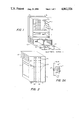
- FIG. 1 is a breakout assembly view of the packaging of a typical electronic system
- FIG. 2 is a view of the back of the system
- FIG. 2A shows the detail of connecting the backplane to the bus bars
- FIGS. 3 through 6 show the various views of the female connector
- FIG. 1 shows the use of a female connector 12 of electronic system 1.
- a number of power supplies 6 supply power to a number of printed circuit boards 4.
- Ground is provided by power supplies 6, blade 30, one of the connectors 12, a bus bar 14, a bushing 25 of FIG. 2A, an etch 5, an etched backplane 3 of integrated backplane assembly 2, a connector 8, an edge connector 9, and printed circuit boards 4.
- Power control signals are transferred between the power supplies 6 via edge connectors 32, connectors 10, and etched backplane 3. Power control signals are transferred between the power supplies 6 via edge connectors 32, connectors 10, etched backplane 3, connectors 8, edge connectors 9, and printed circuit boards 4.
- a guide 18 fastened to etched backplane 3 and containing channels 20 for supporting printed circuit boards 4. Also, a cage 22 provides physical support for power supplies 6.
- Connectors 12 are bolted to bus bars 14 and 16 by means of bolts 26.
- Bus bars 14 and 16 are also fastened to printed circuit boards 4 via bolt 24 into a tapped hole in bushing 25, FIG. 2A.
- Bushing 25 is soldered to the power etches 5 and 7.
- FIG. 2 is a back view of the electronic system 1 packaging showing the bus bars 14 and 16 coupled to backplane 3 of integrated backplane assembly 2.
- Bolts 26 fasten connectors 12 of FIG. 1 to bus bars 14 and 16. Also shown is the guide 18 and the cage 22.
- FIG. 2A shows how the bus bars 14 and 16 are electrically coupled to the etch 5 or 7 by soldering and physically coupled to backplane 3 by the bushing 25 having a threaded hole for receiving screw 24. Note that bus bars 14 and 16 are fastened to the etches 5 and 7 in a number of locations thereby reducing the possibility of circuit ground loops.
- FIGS. 3, 4, 5 and 6 show the top, bottom, side and front views, respectively, of connector 12.
- FIG. 6 shows the sets of fingers 41. Five sets of fingers 41 are shown but this invention is not limited to the five sets of fingers 41.
- connector 12 includes a hole 13 to establish a thin section 15 to act as a fulcrum about which each finger of the sets of fingers 41 will flex when blade 30 of FIG. 7 is inserted.
- the distance between one row of fingers of each set of fingers 41 is related to the centerline of the hole by a dimension 11 and the distance between corresponding fingers of the set of fingers 41 is dimension 31 wherein dimension 31 is twice dimension 11.
- FIG. 4 shows the tapped hole 33 at a predetermined depth sufficient to hold connector 12 securely to bus bar 14 or 16 by bolts 26, FIG. 2.
- FIG. 7 shows power supply 6 having blade 30 mounted to an etched board 33 by means of a block 10 and a screw 13.
- the material of connector 12 is typically a copper beryllium alloy plated with 0.0005 inches of silver.
- the blade 30 material is typically silver-plated copper having a thickness of typical 0.093 inches.
- the current carrying capability of connector 12 of 150 amps DC is determined by the minimum cross-sectional area 15, FIG. 5, of the set of fingers 41. Typically one finger of the set of fingers 41 would have a cross-sectional area 0.00816 square inches or 8160 square mils. Since 1 square mil equals 1.274 circular mils, the cross-sectional area is approximately 10,400 (8160 ⁇ 1.274) circular mils or 104,000 circular mils for 10 fingers.
- the current carrying capacity is 500 circular mils per ampere or 208 amps. This value is deroted to 150 amps for reliability reasons.
- the contact area for carrying the 150 ampere current between the connector 12 and the blade 30 is typically 0.0527 square inches. This contact area occurs after insertion at the dimension 15 located at the tip of each finger. This is calculated by multiplying the width of each finger, typically 0.170 inches by 1/32 inches which approximates the distance perpendicular to the finger width and multiplying by 10, the number of fingers.
- This contact area gives a resistance of 0.00000274 ohms or a voltage drop at 5V DC of approximately 400 microvolts.
Landscapes
- Engineering & Computer Science (AREA)
- Power Engineering (AREA)
- Microelectronics & Electronic Packaging (AREA)
- Coupling Device And Connection With Printed Circuit (AREA)
Abstract
Description
Claims (3)
Priority Applications (1)
| Application Number | Priority Date | Filing Date | Title |
|---|---|---|---|
| US07/183,356 US4862326A (en) | 1985-07-01 | 1988-04-12 | Power supply contact |
Applications Claiming Priority (3)
| Application Number | Priority Date | Filing Date | Title |
|---|---|---|---|
| US06/750,441 US4685032A (en) | 1985-07-01 | 1985-07-01 | Integrated backplane |
| US2015487A | 1987-02-26 | 1987-02-26 | |
| US07/183,356 US4862326A (en) | 1985-07-01 | 1988-04-12 | Power supply contact |
Related Parent Applications (1)
| Application Number | Title | Priority Date | Filing Date |
|---|---|---|---|
| US2015487A Continuation | 1985-07-01 | 1987-02-26 |
Publications (1)
| Publication Number | Publication Date |
|---|---|
| US4862326A true US4862326A (en) | 1989-08-29 |
Family
ID=27361374
Family Applications (1)
| Application Number | Title | Priority Date | Filing Date |
|---|---|---|---|
| US07/183,356 Expired - Fee Related US4862326A (en) | 1985-07-01 | 1988-04-12 | Power supply contact |
Country Status (1)
| Country | Link |
|---|---|
| US (1) | US4862326A (en) |
Cited By (15)
| Publication number | Priority date | Publication date | Assignee | Title |
|---|---|---|---|---|
| US5131859A (en) * | 1991-03-08 | 1992-07-21 | Cray Research, Inc. | Quick disconnect system for circuit board modules |
| US5253144A (en) * | 1990-07-09 | 1993-10-12 | Siemens Aktiengesellschaft | Device housing having an integrated circuit board |
| WO1997034452A1 (en) * | 1996-03-13 | 1997-09-18 | Siemens Nixdorf Informationssysteme Ag | Equipment chassis for electronic equipment |
| US5748451A (en) * | 1996-08-14 | 1998-05-05 | International Business Machines Corporation | Power distribution/stiffener for active back plane technologies |
| DE19810571C1 (en) * | 1998-03-11 | 1999-05-20 | Siemens Nixdorf Inf Syst | Supply voltage contact rail arrangement for assembly group carrier |
| US5997327A (en) * | 1994-10-24 | 1999-12-07 | Bull S.A. | Power connection device |
| GB2356295A (en) * | 1999-11-10 | 2001-05-16 | Socomec Sa | Distributor for plug-in rack, and plug-in rack without wires |
| US6266247B1 (en) * | 1998-08-24 | 2001-07-24 | Racal Instruments Inc. | Power supply connection system |
| EP2440026A3 (en) * | 2010-10-05 | 2013-07-17 | Ixia | High current clamping connector |
| CN104348050A (en) * | 2013-08-08 | 2015-02-11 | 光宝电子(广州)有限公司 | Power source distribution device and assembly method thereof |
| US20150156822A1 (en) * | 2013-12-03 | 2015-06-04 | MAHLE Behr France Rouffach S.A.S. | Electric heater |
| US9431783B1 (en) * | 2015-03-23 | 2016-08-30 | Tyco Electronics Corporation | Electronic system with power bus bar |
| EP3340757A1 (en) * | 2016-12-22 | 2018-06-27 | Hamilton Sundstrand Corporation | Resistance-limited electrical interconnects |
| GB2563395A (en) * | 2017-06-12 | 2018-12-19 | Ge Aviat Systems Ltd | Power distribution rack assembly |
| US10879658B2 (en) * | 2018-08-31 | 2020-12-29 | Hamilton Sundstrand Corporation | Load connectors for power panel assemblies |
Citations (16)
| Publication number | Priority date | Publication date | Assignee | Title |
|---|---|---|---|---|
| US2578346A (en) * | 1948-09-16 | 1951-12-11 | Berkeley J Florian | Mechanism for cutting sheet material |
| DE1061409B (en) * | 1956-05-11 | 1959-07-16 | Licentia Gmbh | Contact facility |
| US3159447A (en) * | 1962-09-21 | 1964-12-01 | Kent Mfg Co | Plug connector for flat conductor cable |
| US3182276A (en) * | 1962-02-26 | 1965-05-04 | Elco Corp | Contact assembly with thermoplastic backing strip |
| AT259661B (en) * | 1966-01-18 | 1968-01-25 | Standard Telephon & Telegraph | Process for the production of fork-shaped edgewise contact springs |
| US3412369A (en) * | 1966-03-23 | 1968-11-19 | Elco Corp | Contact with multiple termination |
| US3470421A (en) * | 1967-08-30 | 1969-09-30 | Sperry Rand Corp | Continuous bus bar for connector plate back panel machine wiring |
| US3533045A (en) * | 1968-05-29 | 1970-10-06 | Amp Inc | Supporting and keying means for printed circuit boards or the like |
| US3689684A (en) * | 1971-02-05 | 1972-09-05 | Du Pont | Lead frame connector and electronic packages containing same |
| US4026622A (en) * | 1976-04-02 | 1977-05-31 | Diamond International Corporation | Electrical connectors and assembly thereof |
| US4029374A (en) * | 1976-05-24 | 1977-06-14 | General Motors Corporation | Electrical connector for printed circuits |
| US4028794A (en) * | 1974-09-09 | 1977-06-14 | Amp Incorporated | Laminated connector |
| US4080027A (en) * | 1976-07-30 | 1978-03-21 | Gte Sylvania Incorporated | Electrical contact and connector |
| US4220382A (en) * | 1978-12-15 | 1980-09-02 | Amp Incorporated | Bussing connector |
| US4242721A (en) * | 1977-10-20 | 1980-12-30 | Bunker Ramo Corporation | Electrical connector assembly for interconnecting remote signal stations to central signal processing systems |
| US4531793A (en) * | 1982-12-09 | 1985-07-30 | Preh Elektrofeinmechanische Werke Jakob Preh Nach. Gmbh & Co. | Multipole edge strip connector |
-
1988
- 1988-04-12 US US07/183,356 patent/US4862326A/en not_active Expired - Fee Related
Patent Citations (16)
| Publication number | Priority date | Publication date | Assignee | Title |
|---|---|---|---|---|
| US2578346A (en) * | 1948-09-16 | 1951-12-11 | Berkeley J Florian | Mechanism for cutting sheet material |
| DE1061409B (en) * | 1956-05-11 | 1959-07-16 | Licentia Gmbh | Contact facility |
| US3182276A (en) * | 1962-02-26 | 1965-05-04 | Elco Corp | Contact assembly with thermoplastic backing strip |
| US3159447A (en) * | 1962-09-21 | 1964-12-01 | Kent Mfg Co | Plug connector for flat conductor cable |
| AT259661B (en) * | 1966-01-18 | 1968-01-25 | Standard Telephon & Telegraph | Process for the production of fork-shaped edgewise contact springs |
| US3412369A (en) * | 1966-03-23 | 1968-11-19 | Elco Corp | Contact with multiple termination |
| US3470421A (en) * | 1967-08-30 | 1969-09-30 | Sperry Rand Corp | Continuous bus bar for connector plate back panel machine wiring |
| US3533045A (en) * | 1968-05-29 | 1970-10-06 | Amp Inc | Supporting and keying means for printed circuit boards or the like |
| US3689684A (en) * | 1971-02-05 | 1972-09-05 | Du Pont | Lead frame connector and electronic packages containing same |
| US4028794A (en) * | 1974-09-09 | 1977-06-14 | Amp Incorporated | Laminated connector |
| US4026622A (en) * | 1976-04-02 | 1977-05-31 | Diamond International Corporation | Electrical connectors and assembly thereof |
| US4029374A (en) * | 1976-05-24 | 1977-06-14 | General Motors Corporation | Electrical connector for printed circuits |
| US4080027A (en) * | 1976-07-30 | 1978-03-21 | Gte Sylvania Incorporated | Electrical contact and connector |
| US4242721A (en) * | 1977-10-20 | 1980-12-30 | Bunker Ramo Corporation | Electrical connector assembly for interconnecting remote signal stations to central signal processing systems |
| US4220382A (en) * | 1978-12-15 | 1980-09-02 | Amp Incorporated | Bussing connector |
| US4531793A (en) * | 1982-12-09 | 1985-07-30 | Preh Elektrofeinmechanische Werke Jakob Preh Nach. Gmbh & Co. | Multipole edge strip connector |
Non-Patent Citations (2)
| Title |
|---|
| Winings, C. L., "A Printed-Circuit-Board Connector Family with up to Forty-Eight Contacts . . . ", Proceedings of 30th Electronic Components, IEEE, Apr. 1980, pp. 332-340. |
| Winings, C. L., A Printed Circuit Board Connector Family with up to Forty Eight Contacts . . . , Proceedings of 30th Electronic Components, IEEE, Apr. 1980, pp. 332 340. * |
Cited By (23)
| Publication number | Priority date | Publication date | Assignee | Title |
|---|---|---|---|---|
| US5253144A (en) * | 1990-07-09 | 1993-10-12 | Siemens Aktiengesellschaft | Device housing having an integrated circuit board |
| US5131859A (en) * | 1991-03-08 | 1992-07-21 | Cray Research, Inc. | Quick disconnect system for circuit board modules |
| US5997327A (en) * | 1994-10-24 | 1999-12-07 | Bull S.A. | Power connection device |
| WO1997034452A1 (en) * | 1996-03-13 | 1997-09-18 | Siemens Nixdorf Informationssysteme Ag | Equipment chassis for electronic equipment |
| US5748451A (en) * | 1996-08-14 | 1998-05-05 | International Business Machines Corporation | Power distribution/stiffener for active back plane technologies |
| DE19810571C1 (en) * | 1998-03-11 | 1999-05-20 | Siemens Nixdorf Inf Syst | Supply voltage contact rail arrangement for assembly group carrier |
| WO1999046966A3 (en) * | 1998-03-11 | 1999-10-21 | Siemens Ag | Device for providing supply voltage to a mounting rack multipoint connector |
| US6266247B1 (en) * | 1998-08-24 | 2001-07-24 | Racal Instruments Inc. | Power supply connection system |
| GB2356295A (en) * | 1999-11-10 | 2001-05-16 | Socomec Sa | Distributor for plug-in rack, and plug-in rack without wires |
| GB2356295B (en) * | 1999-11-10 | 2001-12-05 | Socomec Sa | Electrical power distributor for plug-in rack and plug-in rack |
| EP2440026A3 (en) * | 2010-10-05 | 2013-07-17 | Ixia | High current clamping connector |
| CN104348050A (en) * | 2013-08-08 | 2015-02-11 | 光宝电子(广州)有限公司 | Power source distribution device and assembly method thereof |
| US20150043131A1 (en) * | 2013-08-08 | 2015-02-12 | Lite-On Electronics (Guangzhou) Limited | Power distribution device and assembling method thereof |
| US9538685B2 (en) * | 2013-08-08 | 2017-01-03 | Lite-On Electronics (Guangzhou) Limited | Power distribution device and assembling method thereof |
| US20150156822A1 (en) * | 2013-12-03 | 2015-06-04 | MAHLE Behr France Rouffach S.A.S. | Electric heater |
| US9686823B2 (en) * | 2013-12-03 | 2017-06-20 | Mahle International Gmbh | Electric heater |
| US9431783B1 (en) * | 2015-03-23 | 2016-08-30 | Tyco Electronics Corporation | Electronic system with power bus bar |
| EP3340757A1 (en) * | 2016-12-22 | 2018-06-27 | Hamilton Sundstrand Corporation | Resistance-limited electrical interconnects |
| US10020641B1 (en) | 2016-12-22 | 2018-07-10 | Hamilton Sundstrand Corporation | Resistance-limited electrical interconnects |
| GB2563395A (en) * | 2017-06-12 | 2018-12-19 | Ge Aviat Systems Ltd | Power distribution rack assembly |
| GB2563395B (en) * | 2017-06-12 | 2020-06-17 | Ge Aviat Systems Ltd | Power distribution rack assembly |
| US10784656B2 (en) | 2017-06-12 | 2020-09-22 | Ge Aviation Systems Limited | Power distribution rack assembly |
| US10879658B2 (en) * | 2018-08-31 | 2020-12-29 | Hamilton Sundstrand Corporation | Load connectors for power panel assemblies |
Similar Documents
| Publication | Publication Date | Title |
|---|---|---|
| US4862326A (en) | Power supply contact | |
| EP0207496B1 (en) | Integrated backplane | |
| CA1288139C (en) | Electrical power connector | |
| US4867696A (en) | Laminated bus bar with power tabs | |
| US5158471A (en) | Power connector with current distribution | |
| WO2020103471A1 (en) | Hybrid card-edge connectors and power terminals for high-power applications | |
| US4632476A (en) | Terminal grounding unit | |
| US5525067A (en) | Ground plane interconnection system using multiple connector contacts | |
| US4631637A (en) | Dual backplane interconnect system | |
| US6036508A (en) | Connector for interconnecting a bus bar to a circuit board | |
| US4585284A (en) | Transition adapter connector employing a printed circuit board | |
| EP0306218A1 (en) | Flexible bussing system for distributing power | |
| EP0421960B1 (en) | Function unit for electronic equipment | |
| US4895523A (en) | Controlled impedance connector | |
| TW202143561A (en) | Card-edge connector system with busbar connection for high-power applications | |
| EP0712268A2 (en) | Power distribution connector apparatus for back-to-back sandwiched circuit boards | |
| US5616034A (en) | Power supply apparatus for package | |
| US4464010A (en) | Arrangement for detachably connecting a wire to a circuit board conductor | |
| US5261828A (en) | Misalignment tolerant edge connector assembly | |
| EP0129982A2 (en) | Backpanel assemblies | |
| US5276587A (en) | Pivotable electrical connection apparatus | |
| US6227897B1 (en) | System for high-bandwidth electrical coupling | |
| US20010044239A1 (en) | High current board-to-board power connector | |
| JP2000035838A (en) | Bus for power distribution and its manufacture | |
| CA2132856A1 (en) | Electrical connector |
Legal Events
| Date | Code | Title | Description |
|---|---|---|---|
| FEPP | Fee payment procedure |
Free format text: PAYOR NUMBER ASSIGNED (ORIGINAL EVENT CODE: ASPN); ENTITY STATUS OF PATENT OWNER: LARGE ENTITY |
|
| CC | Certificate of correction | ||
| FPAY | Fee payment |
Year of fee payment: 4 |
|
| FPAY | Fee payment |
Year of fee payment: 8 |
|
| FEPP | Fee payment procedure |
Free format text: PAYER NUMBER DE-ASSIGNED (ORIGINAL EVENT CODE: RMPN); ENTITY STATUS OF PATENT OWNER: LARGE ENTITY Free format text: PAYOR NUMBER ASSIGNED (ORIGINAL EVENT CODE: ASPN); ENTITY STATUS OF PATENT OWNER: LARGE ENTITY |
|
| REMI | Maintenance fee reminder mailed | ||
| LAPS | Lapse for failure to pay maintenance fees | ||
| FP | Lapsed due to failure to pay maintenance fee |
Effective date: 20010829 |
|
| STCH | Information on status: patent discontinuation |
Free format text: PATENT EXPIRED DUE TO NONPAYMENT OF MAINTENANCE FEES UNDER 37 CFR 1.362 |