US4861687A - Battery handle adapter - Google Patents
Battery handle adapter Download PDFInfo
- Publication number
- US4861687A US4861687A US07/226,708 US22670888A US4861687A US 4861687 A US4861687 A US 4861687A US 22670888 A US22670888 A US 22670888A US 4861687 A US4861687 A US 4861687A
- Authority
- US
- United States
- Prior art keywords
- handle
- fingers
- adapter
- spine
- septum
- Prior art date
- Legal status (The legal status is an assumption and is not a legal conclusion. Google has not performed a legal analysis and makes no representation as to the accuracy of the status listed.)
- Expired - Fee Related
Links
Images


Classifications
-
- H—ELECTRICITY
- H01—ELECTRIC ELEMENTS
- H01M—PROCESSES OR MEANS, e.g. BATTERIES, FOR THE DIRECT CONVERSION OF CHEMICAL ENERGY INTO ELECTRICAL ENERGY
- H01M50/00—Constructional details or processes of manufacture of the non-active parts of electrochemical cells other than fuel cells, e.g. hybrid cells
- H01M50/20—Mountings; Secondary casings or frames; Racks, modules or packs; Suspension devices; Shock absorbers; Transport or carrying devices; Holders
- H01M50/256—Carrying devices, e.g. belts
-
- Y—GENERAL TAGGING OF NEW TECHNOLOGICAL DEVELOPMENTS; GENERAL TAGGING OF CROSS-SECTIONAL TECHNOLOGIES SPANNING OVER SEVERAL SECTIONS OF THE IPC; TECHNICAL SUBJECTS COVERED BY FORMER USPC CROSS-REFERENCE ART COLLECTIONS [XRACs] AND DIGESTS
- Y02—TECHNOLOGIES OR APPLICATIONS FOR MITIGATION OR ADAPTATION AGAINST CLIMATE CHANGE
- Y02E—REDUCTION OF GREENHOUSE GAS [GHG] EMISSIONS, RELATED TO ENERGY GENERATION, TRANSMISSION OR DISTRIBUTION
- Y02E60/00—Enabling technologies; Technologies with a potential or indirect contribution to GHG emissions mitigation
- Y02E60/10—Energy storage using batteries
-
- Y—GENERAL TAGGING OF NEW TECHNOLOGICAL DEVELOPMENTS; GENERAL TAGGING OF CROSS-SECTIONAL TECHNOLOGIES SPANNING OVER SEVERAL SECTIONS OF THE IPC; TECHNICAL SUBJECTS COVERED BY FORMER USPC CROSS-REFERENCE ART COLLECTIONS [XRACs] AND DIGESTS
- Y10—TECHNICAL SUBJECTS COVERED BY FORMER USPC
- Y10S—TECHNICAL SUBJECTS COVERED BY FORMER USPC CROSS-REFERENCE ART COLLECTIONS [XRACs] AND DIGESTS
- Y10S16/00—Miscellaneous hardware, e.g. bushing, carpet fastener, caster, door closer, panel hanger, attachable or adjunct handle, hinge, window sash balance
- Y10S16/15—Battery handles
-
- Y—GENERAL TAGGING OF NEW TECHNOLOGICAL DEVELOPMENTS; GENERAL TAGGING OF CROSS-SECTIONAL TECHNOLOGIES SPANNING OVER SEVERAL SECTIONS OF THE IPC; TECHNICAL SUBJECTS COVERED BY FORMER USPC CROSS-REFERENCE ART COLLECTIONS [XRACs] AND DIGESTS
- Y10—TECHNICAL SUBJECTS COVERED BY FORMER USPC
- Y10S—TECHNICAL SUBJECTS COVERED BY FORMER USPC CROSS-REFERENCE ART COLLECTIONS [XRACs] AND DIGESTS
- Y10S294/00—Handling: hand and hoist-line implements
- Y10S294/903—Battery carrier
Definitions
- This invention relates to carrying handles for electric-storage batteries and more particularly to an adapter for connecting a battery handle to elongated finger-hole recesses formed in a battery container.
- the present invention comprehends an adapter for detachably mounting a carrying handle to a battery having elongated finger-hole recesses at each end thereof for lifting/carrying the battery.
- the adapter comprises a comb-like insert adapted to be closely received within the recess and includes an elongated spine having a plurality of fingers projecting from one longitudinal side thereof for binding engagement therein when lifting forces are applied thereto by the handle.
- the weight of the battery acting on the ends of the handle engaging the insert causes the insert to become wedged within the recess.
- the adapter will preferably be integral with the handle and include a plurality of flexible ribs on the end-most fingers for providing an interference fit between the adapter and the recess.
- the adapter may be a separate piece which itself is adapted to engage a separate handle detachable therefrom and accordingly includes a means (e.g., knob) projecting from the spine in a direction opposite to the fingers and outboard the end walls of the battery container for engaging the battery handle.
- a means e.g., knob
- FIG. 1 is an isometric view of a battery of the type benefiting from the present invention
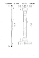
- FIG. 2 is a partially broken away plan view of the battery of FIG. 1 with a separate detachable carrying handle in place thereover;
- FIG. 3 is a partially broken away view in the direction 3--3 of FIG. 2 with the right end of the handle detached from the battery;
- FIG. 4 is a plan view of a discrete adapter in accordance with the present invention.
- FIG. 5 is a partially broken away elevational view of a battery handle and integral adapter in accordance with the preferred embodiment of the present invention.
- FIG. 6 is a plan view in the direction 6--6 of FIG. 5.
- FIG. 1 shows a battery 2 having elongated finger-hole recesses 4 in opposite ends thereof for lifting/carrying the battery 2.
- a vertical septum 6 divides the recess 4 in two parts and serves to strengthen the region of the cover 8 overlying the recess 4.
- a handle 10 such as described in U.S. Pat. No. 4,673,625 issued June 16, 1987 is fitted to the battery 2 by means of an adapter insert 12 sufficiently closely fitted into the recess 4 as to become wedged or bound up tightly within the recess 4 when lifting forces are transmitted by the handle 10 thereto.
- the adapter 12 (best shown in FIG. 4) is sized to fit within the recess 4 in an interference fit and comprises an elongated spine 14 portion having a plurality of fingers 16 projecting from one of its longitudinal sides.
- a knob 18 projects from another side of the spine 14 in a direction opposite that of the fingers 16 and serves as a means to engage a separate detachable handle 10.
- the fingers 16a at the extreme ends of the spine 14 include flexible ribs 19 projecting outwardly therefrom which deflect upon engagement with the end walls 20 of the recess 4 so as to provide a tight fit between the adapter 12 and the spine 14.
- the centermost pair of fingers 22 include inwardly projecting flexible ribs 24 which deflect and grip the septum 6 therebetween as best shown in FIG. 2.
- the opening 26 between the distal ends of the opposing ribs 24 will be slightly less than the thickness of the septum 6 so as to insure a firm gripping action of the septum 6 by the ribs 24.
- the adapter 12 is a separate/discrete part adapted to mate with a separable/detachable handle 10.
- the adapter 28 is formed integrally with the ends of the handle 30 but is otherwise identical to, and functions the same as, the adapter/insert heretofore described in conjunction with FIGS. 2-4.
Abstract
Description
Claims (6)
Priority Applications (1)
| Application Number | Priority Date | Filing Date | Title |
|---|---|---|---|
| US07/226,708 US4861687A (en) | 1988-08-01 | 1988-08-01 | Battery handle adapter |
Applications Claiming Priority (1)
| Application Number | Priority Date | Filing Date | Title |
|---|---|---|---|
| US07/226,708 US4861687A (en) | 1988-08-01 | 1988-08-01 | Battery handle adapter |
Publications (1)
| Publication Number | Publication Date |
|---|---|
| US4861687A true US4861687A (en) | 1989-08-29 |
Family
ID=22850077
Family Applications (1)
| Application Number | Title | Priority Date | Filing Date |
|---|---|---|---|
| US07/226,708 Expired - Fee Related US4861687A (en) | 1988-08-01 | 1988-08-01 | Battery handle adapter |
Country Status (1)
| Country | Link |
|---|---|
| US (1) | US4861687A (en) |
Cited By (8)
| Publication number | Priority date | Publication date | Assignee | Title |
|---|---|---|---|---|
| WO1992020110A1 (en) * | 1991-04-29 | 1992-11-12 | Optima Batteries, Inc. | Cover assembly for rechargeable battery |
| US5637420A (en) * | 1995-09-01 | 1997-06-10 | Globe-Union Inc. | Self-latching handle for storage batteries |
| US5670274A (en) * | 1995-12-18 | 1997-09-23 | Exide Corporation | Battery strap handle |
| US6022638A (en) * | 1997-05-20 | 2000-02-08 | Gnb Technologies, Inc. | Lead-acid battery with handle |
| US6117588A (en) * | 1998-04-29 | 2000-09-12 | Gnb Technologies, Inc. | Detachable battery handle assembly |
| US6187474B1 (en) * | 1999-02-03 | 2001-02-13 | Lucent Technologies Inc. | Battery container |
| US6303247B1 (en) * | 2000-01-28 | 2001-10-16 | Delphi Technologies, Inc. | Battery cover having recessed attachment feature |
| US20190058173A1 (en) * | 2016-11-21 | 2019-02-21 | Lg Chem, Ltd. | Jig set for mounting energy storage system |
Citations (5)
| Publication number | Priority date | Publication date | Assignee | Title |
|---|---|---|---|---|
| US1540155A (en) * | 1924-10-25 | 1925-06-02 | Hood Rubber Co Inc | Detachable metal handle for battery boxes |
| US1679657A (en) * | 1927-03-15 | 1928-08-07 | Warren E Glancy | Battery box |
| US3092520A (en) * | 1959-03-05 | 1963-06-04 | Gen Motors Corp | Battery structure |
| US4029248A (en) * | 1975-05-27 | 1977-06-14 | Gould Inc. | Detachable battery carrying handle |
| US4673625A (en) * | 1986-08-04 | 1987-06-16 | General Motors Corporation | Battery and handle therefor |
-
1988
- 1988-08-01 US US07/226,708 patent/US4861687A/en not_active Expired - Fee Related
Patent Citations (5)
| Publication number | Priority date | Publication date | Assignee | Title |
|---|---|---|---|---|
| US1540155A (en) * | 1924-10-25 | 1925-06-02 | Hood Rubber Co Inc | Detachable metal handle for battery boxes |
| US1679657A (en) * | 1927-03-15 | 1928-08-07 | Warren E Glancy | Battery box |
| US3092520A (en) * | 1959-03-05 | 1963-06-04 | Gen Motors Corp | Battery structure |
| US4029248A (en) * | 1975-05-27 | 1977-06-14 | Gould Inc. | Detachable battery carrying handle |
| US4673625A (en) * | 1986-08-04 | 1987-06-16 | General Motors Corporation | Battery and handle therefor |
Cited By (9)
| Publication number | Priority date | Publication date | Assignee | Title |
|---|---|---|---|---|
| WO1992020110A1 (en) * | 1991-04-29 | 1992-11-12 | Optima Batteries, Inc. | Cover assembly for rechargeable battery |
| US5637420A (en) * | 1995-09-01 | 1997-06-10 | Globe-Union Inc. | Self-latching handle for storage batteries |
| US5670274A (en) * | 1995-12-18 | 1997-09-23 | Exide Corporation | Battery strap handle |
| US6022638A (en) * | 1997-05-20 | 2000-02-08 | Gnb Technologies, Inc. | Lead-acid battery with handle |
| US6117588A (en) * | 1998-04-29 | 2000-09-12 | Gnb Technologies, Inc. | Detachable battery handle assembly |
| US6187474B1 (en) * | 1999-02-03 | 2001-02-13 | Lucent Technologies Inc. | Battery container |
| US6303247B1 (en) * | 2000-01-28 | 2001-10-16 | Delphi Technologies, Inc. | Battery cover having recessed attachment feature |
| US20190058173A1 (en) * | 2016-11-21 | 2019-02-21 | Lg Chem, Ltd. | Jig set for mounting energy storage system |
| US10770702B2 (en) * | 2016-11-21 | 2020-09-08 | Lg Chem, Ltd. | Jig set including handle for mounting energy storage system |
Similar Documents
| Publication | Publication Date | Title |
|---|---|---|
| US5346063A (en) | Tool holder | |
| US4861687A (en) | Battery handle adapter | |
| AU550537B2 (en) | Hose coupling | |
| WO2002014162A3 (en) | Removable grip for a bucket | |
| ES281748U (en) | A razor handle. | |
| ES266698U (en) | Pipe clamp. | |
| US5890635A (en) | Carrying attachment for a container | |
| EP1043518A3 (en) | Guide chain | |
| CA2106023A1 (en) | Surgical Blade Holder and Blade Combination | |
| US4282783A (en) | Handles for pliers | |
| USD294988S (en) | Handle grip for a vacuum cleaner | |
| USD290746S (en) | Louvered vent for boats | |
| CA1266625A (en) | Tin can lid for out-of-round cans, in particular cans of oblong shape in hansa format | |
| US4352307A (en) | Socket wrench with interchangeable sockets stored in handle | |
| USD353748S (en) | Handled lunchbox | |
| USD394073S (en) | Magnifier with gripper handle | |
| USD263326S (en) | Jump rope | |
| CA2069251A1 (en) | Sheet-like separator and valve regulated lead acid battery | |
| USD407450S (en) | Jump rope | |
| USD309565S (en) | Grocery bag with handgrips | |
| USD278971S (en) | Hand grip handle for detachable tools | |
| KR850003029Y1 (en) | Hand-gripping equipment | |
| USD285329S (en) | Hand grip exerciser | |
| USD242984S (en) | Hand grip | |
| USD279033S (en) | Handle for a curling iron or styler |
Legal Events
| Date | Code | Title | Description |
|---|---|---|---|
| AS | Assignment |
Owner name: GENERAL MOTORS CORPORATION, DETROIT, MI. A CORP. O Free format text: ASSIGNMENT OF ASSIGNORS INTEREST.;ASSIGNORS:BRANTLEY, RANDALL F.;MCVEY, HARRY D.;REEL/FRAME:004930/0081;SIGNING DATES FROM 19880617 TO 19880629 Owner name: GENERAL MOTORS CORPORATION, A CORP. OF DE., MICHIG Free format text: ASSIGNMENT OF ASSIGNORS INTEREST;ASSIGNORS:BRANTLEY, RANDALL F.;MCVEY, HARRY D.;SIGNING DATES FROM 19880617 TO 19880629;REEL/FRAME:004930/0081 |
|
| FEPP | Fee payment procedure |
Free format text: PAYOR NUMBER ASSIGNED (ORIGINAL EVENT CODE: ASPN); ENTITY STATUS OF PATENT OWNER: LARGE ENTITY |
|
| REMI | Maintenance fee reminder mailed | ||
| FPAY | Fee payment |
Year of fee payment: 4 |
|
| SULP | Surcharge for late payment | ||
| REMI | Maintenance fee reminder mailed | ||
| LAPS | Lapse for failure to pay maintenance fees | ||
| FP | Lapsed due to failure to pay maintenance fee |
Effective date: 19970903 |
|
| STCH | Information on status: patent discontinuation |
Free format text: PATENT EXPIRED DUE TO NONPAYMENT OF MAINTENANCE FEES UNDER 37 CFR 1.362 |