US4859202A - Electrical connector having strain relief - Google Patents
Electrical connector having strain relief Download PDFInfo
- Publication number
- US4859202A US4859202A US07/187,132 US18713288A US4859202A US 4859202 A US4859202 A US 4859202A US 18713288 A US18713288 A US 18713288A US 4859202 A US4859202 A US 4859202A
- Authority
- US
- United States
- Prior art keywords
- slots
- exit chamber
- electrical
- strain relief
- wall
- Prior art date
- Legal status (The legal status is an assumption and is not a legal conclusion. Google has not performed a legal analysis and makes no representation as to the accuracy of the status listed.)
- Expired - Fee Related
Links
Images
Classifications
-
- H—ELECTRICITY
- H01—ELECTRIC ELEMENTS
- H01R—ELECTRICALLY-CONDUCTIVE CONNECTIONS; STRUCTURAL ASSOCIATIONS OF A PLURALITY OF MUTUALLY-INSULATED ELECTRICAL CONNECTING ELEMENTS; COUPLING DEVICES; CURRENT COLLECTORS
- H01R13/00—Details of coupling devices of the kinds covered by groups H01R12/70 or H01R24/00 - H01R33/00
- H01R13/58—Means for relieving strain on wire connection, e.g. cord grip, for avoiding loosening of connections between wires and terminals within a coupling device terminating a cable
- H01R13/582—Means for relieving strain on wire connection, e.g. cord grip, for avoiding loosening of connections between wires and terminals within a coupling device terminating a cable the cable being clamped between assembled parts of the housing
-
- H—ELECTRICITY
- H01—ELECTRIC ELEMENTS
- H01R—ELECTRICALLY-CONDUCTIVE CONNECTIONS; STRUCTURAL ASSOCIATIONS OF A PLURALITY OF MUTUALLY-INSULATED ELECTRICAL CONNECTING ELEMENTS; COUPLING DEVICES; CURRENT COLLECTORS
- H01R4/00—Electrically-conductive connections between two or more conductive members in direct contact, i.e. touching one another; Means for effecting or maintaining such contact; Electrically-conductive connections having two or more spaced connecting locations for conductors and using contact members penetrating insulation
- H01R4/24—Connections using contact members penetrating or cutting insulation or cable strands
- H01R4/2416—Connections using contact members penetrating or cutting insulation or cable strands the contact members having insulation-cutting edges, e.g. of tuning fork type
- H01R4/2445—Connections using contact members penetrating or cutting insulation or cable strands the contact members having insulation-cutting edges, e.g. of tuning fork type the contact members having additional means acting on the insulation or the wire, e.g. additional insulation penetrating means, strain relief means or wire cutting knives
Definitions
- This invention relates generally to electrical connectors and more particularly to electrical connectors having terminals attached to electrical leads which lead out of a connector body.
- the object of this invention is to provide an electrical connector of this type with a strain relief which firmly holds the electrical lead or leads to the terminal body.
- a feature of the invention is that the strain relief kinks the electrical lead laterally to pass through a labyrinthian exit path created by the strain relief to firmly hold the electrical lead in the longitudinal direction of the electrical lead.
- strain relief cooperates with the connector body to firmly hold the electrical lead in the lateral direction of the electrical lead.
- strain relief cooperates with the connector body to firmly hold the electrical lead in the lateral direction as well as the longitudinal direction of the electrical lead so that the strain relief is particularly well suited for use with insulation displacement terminals.
- strain relief include means for retaining the electrical lead in insulation displacement slots of an insulation displacement terminal when the strain relief is used in conjunction with an insulation displacement terminal.
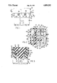
- FIG. 1 is a fragmentary elevational view of an electrical connector having a strain relief in accordance with the invention.
- FIG. 2 is a section taken substantially along the line 2--2 of FIG. 1 looking in the direction of the arrows.
- FIG. 3 is a section taken substantially along the line 3--3 of FIG. 2 looking in the direction of the arrows.
- an electrical connector 10 in accordance with the invention comprises a connector body 12 which houses a pair of insulation displacement terminals 14 and 16 attached to electrical leads 18 and 20 and a strain relief cover 22.
- the electrical connector 10 is a right angle connector in which the electrical leads 18 and 20 are perpendicular, that is, at a right angle with respect to the longitudinal axis of the terminals 14 and 16.
- the invention may also be embodied in an in-line connector where the electrical leads are disposed in the same longitudinal direction as the longitudinal axis of the terminals.
- the insulation displacement terminals 14 and 16 have box-shaped attachment portions 24 which are disposed in the open end portions of the terminal cavities 23 and 25 of the connector body 12 as best seen in FIG. 2.
- the box-shaped attachment portions 24 of the terminals include spaced side walls 26 having insulation displacement slots 28.
- the electrical leads 18 and 20 are attached to the terminals 14 and 16 in a well known manner, that is, by laterally inserting the leads 18 and 20 into the insulation displacement slots 28 so that the side walls 26 cut through the insulation and engage the conductive cores of the electrical leads.
- the connector body 14 has an exit chamber 30 which communicates with the terminal cavities 23 and 25 through slots 32 which extend through the wall 34 separating the exit chamber 30 from the terminal cavities 23 and 25.
- the opposite wall 36 of the exit chamber 30 has slots 38 which are aligned with the slots 32 which in turn are aligned with the insulation displacement slots 28 of the respective terminals 14 and 16.
- the slots 32 have a lead-in but the width of the slots 32 in the separating wall 34 is preferably less than the diameter of the electrical leads 18 and 20 so that the insulation of the electrical leads is pinched and tightly gripped when the electrical leads 18 and 20 are pushed down into the slots 32.
- the width of the slots 38 in the opposite exterior wall 36 are preferably slightly larger than the diameter of the electrical leads 18 and 20 so that the lead may be inserted easily. This facilitates lateral insertion of the electrical leads 18 and 20 into the insulation gripping slots 32 and the insulation displacement slots 28 of the terminals 14 and 16.
- the exit chamber 30 also has shelves 39 which are near the outer sides of the slots 32 and 38 at the bottom level of the slots as shown in FIGS. 2 and 3.
- the strain relief cover 22 has a depending blade 40 which projects into the exit chamber 30 when the strain relief cover 22 is attached to the connector body 12.
- the depending blade 40 has a tapered terminus 42 and intermediate opposite side walls 44 which partially block the respective straight line paths from the slots 32 to the slots 38 thereby creating labyrinthian passages for the electrical leads 18 and 20 when the blade 40 is inserted into the exit chamber 30.
- the upper end of the blade 40 is enlarged to provide abutment shoulders 46 for holding the electrical lead 18 and 20 down against the shelves 39 as shown in FIG. 3.
- the strain relief cover 22 also includes depending cross members 48 which are integrally connected to the blade 40.
- the cross members 48 have opposite end portions which enter the slots 32 and 38 to hold the electrical leads 18 and 20 down in the connector body 12 at these locations.
- the strain relief cover 22 also includes depending terminal projections 50 which are aligned with the respective cross members 48 and which project into the box-shaped attachment portions 24 of the terminals 14 and 16 to hold the electric leads 18 and 20 down in the insulation displacement slots 28.
- the electrical connector 10 is assembled by loading the terminals 14 and 16 into the connector body 12 and then inserting the electrical leads 18 and 20 laterally into the insulation displacement slots 28 of the respective terminals and into the slots 32 and 38 on either side of the exit chamber 30.
- the strain relief cover 22 is then attached.
- the depending blade 40 engages and kinks the electrical leads 18 and 20 laterally away from each other to pass through the labyrinthian paths which are created when the depending blade 20 is inserted into the exit chamber 30 as shown in FIG. 2.
- the shoulders 46 of the depending blade 40 engage the laterally kinked portions of the electrical leads 18 and 20 and hold them against the shelves 39 in the exit chamber 30 as shown in FIG. 3.
- the cross members 48 and projections 50 also engage the electrical leads 18 and 20 to insure that the electrical leads are firmly held in the lateral direction and properly seated in the insulation displacement slots 28 of the terminals 14 and 16 and in the slots 32 and 38 of the connector body 12.
- the strain relief cover is retained by conventional latch arms 52 which engage lock nibs 54 of the connector body 12.
Abstract
Description
Claims (6)
Priority Applications (1)
| Application Number | Priority Date | Filing Date | Title |
|---|---|---|---|
| US07/187,132 US4859202A (en) | 1988-04-28 | 1988-04-28 | Electrical connector having strain relief |
Applications Claiming Priority (1)
| Application Number | Priority Date | Filing Date | Title |
|---|---|---|---|
| US07/187,132 US4859202A (en) | 1988-04-28 | 1988-04-28 | Electrical connector having strain relief |
Publications (1)
| Publication Number | Publication Date |
|---|---|
| US4859202A true US4859202A (en) | 1989-08-22 |
Family
ID=22687733
Family Applications (1)
| Application Number | Title | Priority Date | Filing Date |
|---|---|---|---|
| US07/187,132 Expired - Fee Related US4859202A (en) | 1988-04-28 | 1988-04-28 | Electrical connector having strain relief |
Country Status (1)
| Country | Link |
|---|---|
| US (1) | US4859202A (en) |
Cited By (1)
| Publication number | Priority date | Publication date | Assignee | Title |
|---|---|---|---|---|
| WO1994018721A1 (en) * | 1993-02-05 | 1994-08-18 | Henry Guy Stevens | Electric plugs |
Citations (5)
| Publication number | Priority date | Publication date | Assignee | Title |
|---|---|---|---|---|
| US3860318A (en) * | 1973-04-04 | 1975-01-14 | Amp Inc | Pre-loaded electrical connector |
| US4029896A (en) * | 1975-10-22 | 1977-06-14 | Electro-Therm, Inc. | Terminal housing for an electrical resistance heater |
| US4195898A (en) * | 1977-12-27 | 1980-04-01 | Bunker Ramo Corporation | Patchcord connector |
| US4634211A (en) * | 1982-09-30 | 1987-01-06 | Leviton Manufacturing Company, Inc. | Wiring device system with single screw subassembly |
| US4759723A (en) * | 1986-06-27 | 1988-07-26 | The Siemon Company | Patch connector |
-
1988
- 1988-04-28 US US07/187,132 patent/US4859202A/en not_active Expired - Fee Related
Patent Citations (5)
| Publication number | Priority date | Publication date | Assignee | Title |
|---|---|---|---|---|
| US3860318A (en) * | 1973-04-04 | 1975-01-14 | Amp Inc | Pre-loaded electrical connector |
| US4029896A (en) * | 1975-10-22 | 1977-06-14 | Electro-Therm, Inc. | Terminal housing for an electrical resistance heater |
| US4195898A (en) * | 1977-12-27 | 1980-04-01 | Bunker Ramo Corporation | Patchcord connector |
| US4634211A (en) * | 1982-09-30 | 1987-01-06 | Leviton Manufacturing Company, Inc. | Wiring device system with single screw subassembly |
| US4759723A (en) * | 1986-06-27 | 1988-07-26 | The Siemon Company | Patch connector |
Cited By (2)
| Publication number | Priority date | Publication date | Assignee | Title |
|---|---|---|---|---|
| WO1994018721A1 (en) * | 1993-02-05 | 1994-08-18 | Henry Guy Stevens | Electric plugs |
| GB2291546A (en) * | 1993-02-05 | 1996-01-24 | Henry Guy Stevens | Electric plugs |
Similar Documents
| Publication | Publication Date | Title |
|---|---|---|
| US4220388A (en) | Electrical connector and contact and housing therefor | |
| CA1213954A (en) | Connector having means for positively seating contacts | |
| US4472017A (en) | Tab receptacle terminal | |
| KR100241845B1 (en) | Electrical connector having terminals with improved retention means | |
| US4527852A (en) | Multigauge insulation displacement connector and contacts therefor | |
| US4557543A (en) | Key hole retention | |
| US3065448A (en) | Terminal means | |
| US5443403A (en) | Composite electrical connector assembly with snap-in housing | |
| US4405193A (en) | Preloaded electrical connector | |
| US5735706A (en) | Cramping connector | |
| US4438998A (en) | Modular plug-dial modular jack adaptor | |
| CA2002545A1 (en) | Modular plug for terminating cordage | |
| US6764333B2 (en) | RJ-type male plug with integral wire shields | |
| EP0716477B1 (en) | Modular plug for high speed data transmission | |
| JP2804941B2 (en) | Terminal insert | |
| EP0644618A2 (en) | Electrical connector with improved terminal latching means | |
| WO2008033596B1 (en) | Ethernet connector apparatus and method | |
| US6398599B1 (en) | Male contact having contact entangling prevention means | |
| US4859202A (en) | Electrical connector having strain relief | |
| US5224876A (en) | Electrical connector | |
| EP0043200B1 (en) | Electrical connector assembly with releasably retained terminals | |
| JPH059905B2 (en) | ||
| USRE32898E (en) | Multigauge insulation displacement connector and contacts therefor | |
| US5195913A (en) | Terminal block having improved terminal cavity | |
| JPH0729582Y2 (en) | Connector holder |
Legal Events
| Date | Code | Title | Description |
|---|---|---|---|
| AS | Assignment |
Owner name: GENERAL MOTORS CORPORATION, DETROIT, MICHIGAN, A C Free format text: ASSIGNMENT OF ASSIGNORS INTEREST.;ASSIGNOR:NESTOR, CHARLES R.;REEL/FRAME:004902/0346 Effective date: 19880607 Owner name: GENERAL MOTORS CORPORATION, A CORP. OF DE., MICHIG Free format text: ASSIGNMENT OF ASSIGNORS INTEREST;ASSIGNOR:NESTOR, CHARLES R.;REEL/FRAME:004902/0346 Effective date: 19880607 |
|
| FEPP | Fee payment procedure |
Free format text: PAYOR NUMBER ASSIGNED (ORIGINAL EVENT CODE: ASPN); ENTITY STATUS OF PATENT OWNER: LARGE ENTITY |
|
| REMI | Maintenance fee reminder mailed | ||
| FPAY | Fee payment |
Year of fee payment: 4 |
|
| SULP | Surcharge for late payment | ||
| FPAY | Fee payment |
Year of fee payment: 8 |
|
| REMI | Maintenance fee reminder mailed | ||
| LAPS | Lapse for failure to pay maintenance fees | ||
| FP | Lapsed due to failure to pay maintenance fee |
Effective date: 20010822 |
|
| STCH | Information on status: patent discontinuation |
Free format text: PATENT EXPIRED DUE TO NONPAYMENT OF MAINTENANCE FEES UNDER 37 CFR 1.362 |