US4845763A - Tool wear measurement by machine vision - Google Patents
Tool wear measurement by machine vision Download PDFInfo
- Publication number
- US4845763A US4845763A US07/118,277 US11827787A US4845763A US 4845763 A US4845763 A US 4845763A US 11827787 A US11827787 A US 11827787A US 4845763 A US4845763 A US 4845763A
- Authority
- US
- United States
- Prior art keywords
- wear
- tool
- edges
- image
- face
- Prior art date
- Legal status (The legal status is an assumption and is not a legal conclusion. Google has not performed a legal analysis and makes no representation as to the accuracy of the status listed.)
- Expired - Fee Related
Links
- 238000005259 measurement Methods 0.000 title description 30
- 238000000034 method Methods 0.000 claims abstract description 30
- 230000008569 process Effects 0.000 claims description 5
- 238000012545 processing Methods 0.000 abstract description 9
- 230000002452 interceptive effect Effects 0.000 abstract description 5
- 238000010191 image analysis Methods 0.000 abstract description 2
- 238000000691 measurement method Methods 0.000 abstract description 2
- 238000004590 computer program Methods 0.000 abstract 1
- 238000003754 machining Methods 0.000 description 7
- 239000000835 fiber Substances 0.000 description 4
- 238000012360 testing method Methods 0.000 description 4
- 230000001788 irregular Effects 0.000 description 3
- 238000010586 diagram Methods 0.000 description 2
- 230000003993 interaction Effects 0.000 description 2
- 238000004458 analytical method Methods 0.000 description 1
- 230000001174 ascending effect Effects 0.000 description 1
- 239000010953 base metal Substances 0.000 description 1
- 238000004364 calculation method Methods 0.000 description 1
- 230000008859 change Effects 0.000 description 1
- 238000012512 characterization method Methods 0.000 description 1
- 239000003086 colorant Substances 0.000 description 1
- 238000011161 development Methods 0.000 description 1
- 230000018109 developmental process Effects 0.000 description 1
- 230000003628 erosive effect Effects 0.000 description 1
- 238000009499 grossing Methods 0.000 description 1
- 238000005286 illumination Methods 0.000 description 1
- 238000011005 laboratory method Methods 0.000 description 1
- 239000000463 material Substances 0.000 description 1
- 230000007246 mechanism Effects 0.000 description 1
- 230000000877 morphologic effect Effects 0.000 description 1
- 238000007781 pre-processing Methods 0.000 description 1
- 238000011160 research Methods 0.000 description 1
- 230000011218 segmentation Effects 0.000 description 1
- 239000007787 solid Substances 0.000 description 1
Images


Classifications
-
- G—PHYSICS
- G01—MEASURING; TESTING
- G01B—MEASURING LENGTH, THICKNESS OR SIMILAR LINEAR DIMENSIONS; MEASURING ANGLES; MEASURING AREAS; MEASURING IRREGULARITIES OF SURFACES OR CONTOURS
- G01B11/00—Measuring arrangements characterised by the use of optical techniques
- G01B11/24—Measuring arrangements characterised by the use of optical techniques for measuring contours or curvatures
-
- B—PERFORMING OPERATIONS; TRANSPORTING
- B23—MACHINE TOOLS; METAL-WORKING NOT OTHERWISE PROVIDED FOR
- B23Q—DETAILS, COMPONENTS, OR ACCESSORIES FOR MACHINE TOOLS, e.g. ARRANGEMENTS FOR COPYING OR CONTROLLING; MACHINE TOOLS IN GENERAL CHARACTERISED BY THE CONSTRUCTION OF PARTICULAR DETAILS OR COMPONENTS; COMBINATIONS OR ASSOCIATIONS OF METAL-WORKING MACHINES, NOT DIRECTED TO A PARTICULAR RESULT
- B23Q17/00—Arrangements for observing, indicating or measuring on machine tools
- B23Q17/09—Arrangements for observing, indicating or measuring on machine tools for indicating or measuring cutting pressure or for determining cutting-tool condition, e.g. cutting ability, load on tool
- B23Q17/0904—Arrangements for observing, indicating or measuring on machine tools for indicating or measuring cutting pressure or for determining cutting-tool condition, e.g. cutting ability, load on tool before or after machining
- B23Q17/0909—Detection of broken tools
-
- B—PERFORMING OPERATIONS; TRANSPORTING
- B23—MACHINE TOOLS; METAL-WORKING NOT OTHERWISE PROVIDED FOR
- B23Q—DETAILS, COMPONENTS, OR ACCESSORIES FOR MACHINE TOOLS, e.g. ARRANGEMENTS FOR COPYING OR CONTROLLING; MACHINE TOOLS IN GENERAL CHARACTERISED BY THE CONSTRUCTION OF PARTICULAR DETAILS OR COMPONENTS; COMBINATIONS OR ASSOCIATIONS OF METAL-WORKING MACHINES, NOT DIRECTED TO A PARTICULAR RESULT
- B23Q17/00—Arrangements for observing, indicating or measuring on machine tools
- B23Q17/09—Arrangements for observing, indicating or measuring on machine tools for indicating or measuring cutting pressure or for determining cutting-tool condition, e.g. cutting ability, load on tool
- B23Q17/0904—Arrangements for observing, indicating or measuring on machine tools for indicating or measuring cutting pressure or for determining cutting-tool condition, e.g. cutting ability, load on tool before or after machining
- B23Q17/0919—Arrangements for measuring or adjusting cutting-tool geometry in presetting devices
- B23Q17/0928—Cutting angles of lathe tools
-
- B—PERFORMING OPERATIONS; TRANSPORTING
- B23—MACHINE TOOLS; METAL-WORKING NOT OTHERWISE PROVIDED FOR
- B23Q—DETAILS, COMPONENTS, OR ACCESSORIES FOR MACHINE TOOLS, e.g. ARRANGEMENTS FOR COPYING OR CONTROLLING; MACHINE TOOLS IN GENERAL CHARACTERISED BY THE CONSTRUCTION OF PARTICULAR DETAILS OR COMPONENTS; COMBINATIONS OR ASSOCIATIONS OF METAL-WORKING MACHINES, NOT DIRECTED TO A PARTICULAR RESULT
- B23Q17/00—Arrangements for observing, indicating or measuring on machine tools
- B23Q17/24—Arrangements for observing, indicating or measuring on machine tools using optics or electromagnetic waves
- B23Q17/248—Arrangements for observing, indicating or measuring on machine tools using optics or electromagnetic waves using special electromagnetic means or methods
- B23Q17/249—Arrangements for observing, indicating or measuring on machine tools using optics or electromagnetic waves using special electromagnetic means or methods using image analysis, e.g. for radar, infrared or array camera images
Definitions
- This invention relates to tool wear measurement and particularly to such measurement using machine vision techniques.
- Tool wear has been extensively studied by the machine tool industry and academia for over 50 years. In general, research has focused on correlating tool wear with machining signals, mainly cutting forces, tool vibration, and cutting temperature, to provide the necessary process information needed for the development of intelligent unmanned machining systems. Although these machining signals can be easily measured, an accurate and reliable method of measuring cutting tool wear has not been developed and thus the accurate correlation of machining signals to tool wear has not been possible.
- machining signals mainly cutting forces, tool vibration, and cutting temperature
- flank wear During machining, the failure of a cutting tool is caused by wear due to the interactions between the tool and the workpiece (flank wear and between the tool and the chip (crater wear).
- Guidelines and specifications for flank and crater wear measurement are available in machining handbooks. Traditionally, these small wear parameters are measured under laboratory conditions, using a toolmaker's microscope. However, these measurements provide a limited definition of the wear of a cutting edge. Tool wear is not simple in nature and because of the irregular boundaries and the varying surface textures, the flank and crater wear boundaries are difficult to define. As a result, measurements of the width or length of flank and crater wear contours are only approximations and are not repeatable because of measurement error.
- the method of the invention is carried out by the steps of; illuminating a cutting tool face by directing light toward the face at an angle which shows contrast between worn and unworn surface regions, acquiring and storing a digitally encoded image of the cutting tool face, segmenting wear regions of the image on the basis of the contrast, and measuring the dimensions of the segmented wear regions.
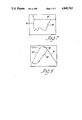
- FIG. 1 is a flank face view of a portion of a cutting tool showing a typical wear pattern and the dimensions for quantifying the wear
- FIG. 2 is a rake face view of a portion of a cutting tool showing a typical wear pattern and the dimensions for quantifying the wear,
- FIG. 3 is a schematic diagram of a tool wear measurement for carrying out the method of the invention
- FIG. 4 is perspective view of a tool measurement setup for carrying out the method of the invention
- FIGS. 5 and 6 are views of images developed by machine vision of the flank face and rake face respectively as generated at an intermediate step in the method of the invention.
- FIGS. 7 and 8 are views of images developed by machine vision of the flank face and rake face respectively showing the boundary lines and the wear regions of the tool according to the method of the invention.
- flank wear is illustrated in FIG. 1 which shows the side view or flank face of a single point cutting tool of a kind commonly used in turning operations.
- the total wear A F visible on the flank face is made up of a minor chipped area A 1 which is not always evident in a given tool, and a major wear region A 2 caused by rubbing against the part being machined.
- the width and length of the wear regions are also useful parameters. Thus the following parameters are to be measured to define flank wear.
- Average wear land width, W avF A F /L F where L F is the contact length between the tool and workpiece.
- FIG. 2 is the top view or the rake face.
- the rounded nose of a new tool becomes worn off to assume a worn tool profile having a larger radius nose than the new tool.
- the area A 3 shown in the FIG. 2 is thus no longer present but must be measured nonetheless.
- the following parameters need to be measured to define crater wear:
- FIG. 3 The block diagram of the tool wear measurement system is shown in FIG. 3.
- a cutting tool 10 is positioned under a microscope 12 using a tool holding fixture, not shown.
- the fixture locates the tool accurately in the image plane of the microscope 12 for observation of either the flank or rake surface.
- Noncoherent light is used for illumination.
- Lighting is controlled using fiber optic guides to achieve the best contrast between the wear areas, the base material and the background.
- FIG. 4 best illustrates the lighting system.
- the tool 10 is shown with the rake surface 14 facing the microscope 12 and the flank surface 16 facing sideways.
- a background panel 18 having a color selected to provide image contrast is positioned at one side of the tool 10 opposite the microscope 12.
- Fiber optic emitters 20 and 22 are positioned to direct high intensity light onto the crater area of the tool from two different directions.
- the emitters 20 and 22 are positioned at shallow angles A and B with respect to the surface. Angles A and B on the order of 15 to 30 degrees have proven to be suitable, although 15 to 20 degrees, is usually preferred.
- a third fiber optic emitter 24 is directed downwardly to illuminate the background panel 18. The light is supplied to the emitters 20-24 by the fiber optic illuminator 26 shown in FIG. 3. The light intensity of the emitters is individually adjustable to allow the contrast to be optimized.
- the lighting is adjusted to obtain contrast between the wear region and the base metal, or unworn region of the tool face.
- contrast is obtained between the tool and the background 18.
- the background may appear to be darker or lighter than the tool.
- the wear region may be darker or lighter than the base. This is determined by the selection of lighting angles and intensities.
- a solid state CCD camera 27 with 488 ⁇ 380 pixel resolution is mounted on the microscope 12 which is set for a magnification of ⁇ 12.
- the camera 27 produces video signals in the standard RS-170 format.
- a Hotronics time base corrector 28 is connected to the video output of the camera to eliminate synchronization problems on the image analysis system 30.
- a suitable high performance image processing system for this application is made by Vicom Systems, Inc., San Jose, Calif. and is based on a Motorola 68000 microprocessor and Versabus.
- the system memory includes four high resolution image planes (512 ⁇ 512 ⁇ 16) and a vision array processor is used for real time image processing as well as general purpose computations.
- the tool wear analysis software is written in PASCAL and uses various VICOM image processing commands. Each processing step can be displayed on a color monitor 32, and the measurement results are sent to a mainframe computer for further analysis.
- a terminal 34 is used for operator input.
- Tool image acquisition and preprocessing is accomplished by reading 16 images of a single point cutting tool which are digitized and averaged to reduce the camera and digitizer electronic noise. Then, a simple contrast stretching operation is performed to enhance the image. The image at this point in the process has fairly sharp outer boundaries except where the tool edge is chipped. Such images are shown in FIGS. 5 and 6 for the flank face and the rake face respectively, except that the images lack the lines 40-48 which are added later.
- the gray background 18' shows the panel 18 surrounding a corner of the tool image 10'.
- the light area in the corner of the tool image is the wear area corresponding to A 2 of FIG. 1.
- the darker area on the tool image is mottled in places.
- FIG. 5 the gray background 18' shows the panel 18 surrounding a corner of the tool image 10'.
- the light area in the corner of the tool image is the wear area corresponding to A 2 of FIG. 1.
- the darker area on the tool image is mottled in places.
- FIG. 5 the gray background 18' shows
- the background 18' is shown as lighter than the tool image 10'.
- the crater wear region corresponding to A 4 of FIG. 2 is shaded much like the unworn face but some boundaries are evident.
- Light areas 36 on the nose and on the left side of the tool image reveal chipped edges and make the tool edge less definite in appearance.
- the wear region may have the appearance of a partly cloudy sky with some of the "cloud" edges representing the wear boundary and other edges presenting misleading information.
- human vision can discern the true boundaries and thus an operator's judgement interacting with machine vision capabilities is used to segment the image into base and wear regions.
- Interactive segmentation follows image acquisition and has two phases.
- the first phase is to extract the edges of a new tool profile by extrapolating a portion of the remaining edges of the worn tool.
- Interactive thresholding is performed on the image using operator selection of threshold level. This operation continues to better define the outer tool edges until the operator is satisfied with the result.
- two edge points 38 on each unworn edge are selected to define the edges 40 and 41 for the new (unworn) tool profile.
- the edges or boundary lines 40 and 41 are extrapolated by the program and superimposed on the image.
- the edge 40 in each case is the edge in primary contact with the workpiece.
- the software computes the nose angle of the tool to identify which view is being analyzed.
- the program identifies that the rake face (crater wear) image is being processed and a circular arc 42 is drawn by the analyzer 30 to designate the new tool nose radius according to the tool manufacturer's specification stored in the analyzer 30.
- a circle 43 is drawn along the worn nose to define the present boundary and form a basis for calculation of nose wear depicted as area A 3 in FIG. 2.
- the circle appears to be an ellipse due to system induced distortion, as discussed below.
- the new tool boundary 41 for the left side is outside the light wear area thus showing that the side has been eroded.
- the wear area is segmented interactively.
- This area generally has different intensities due to irregularities in wear surface texture, causing variations in reflection.
- a simple thresholding operation for the entire wear area is impossible and local thresholding is used, edges being identified where the light intensity gradient of neighboring pixels reaches a threshold value.
- edges displayed over the image which include true boundaries 44 as well as spurious edges 46.
- the boundaries of the chipped areas 36 are shown. Operator interaction is needed to sort out the true boundaries.
- a windowing technique is used to connect the edges that define the boundary 44 of the wear area. The operator uses the cursor to select window size and placement on edge portions of interest.
- Rectangular windows 48 are generated using a cursor and the program selects boundary segments lying only in the windows. Several windows are used, one at a time, along the boundary line 44. An accept command stores the edge in the image plane for later computation. This interactive procedure continues until all edges are selected. The results of each operation can be displayed using various colors on the graphics monitor. To obtain information about chipped edges, the boundaries of the chipped areas 36 are determined interactively and displayed in a different color. During the operation, important variables such as new tool boundary line equations, and coordinates of each window are stored in a data file.
- a region of interest for the wear area is defined.
- Edge smoothing using a morphological operation is employed to eliminate spurious edges or holes.
- the coordinates of boundary points are obtained.
- the resulting boundary is shown in FIGS. 7 and 8.
- the wear area is computed by adding the number of pixels in the line pieces defined by the boundary points.
- the row coordinates of the points are sorted in ascending order to group the horizontal line pieces.
- the wear region is rotated with respect to the image plane origin using the slope of the new tool boundary line 40. This locates the boundary line along the axis such that the height of the region is the contact length of the tool.
- the maximum width of the wear region is also derived from the width of the rotated image.
- the average width of the wear region is computed from the ratio of the area to the contact length. Results are displayed using the color graphics.
- data on the tool wear parameters are stored in an output file.
- the data include the wear area, number of edge points, slope of the new tool boundary line, extreme projection points on the new tool edge, and the heights and widths of each wear region.
- Specific wear data such as the eroded area measured from the flank view of a chipped tool, or the average nose radius of a worn tool as measured from the rake view are also stored.
- the following tables show typical data derived from the measurements. This data was obtained for repeatability tests and show that very small variations result from the procedure.
- the image processing software computed the wear lengths and areas in terms of pixel counts, it is necessary to determine the proper calibration factors (mm/pixel) to compute the absolute value of the wear parameters. Due to the aspect ratio of the camera and the image digitization rate of the VICOM system, the pixels are displayed such that each pixel is stretched more in the horizontal direction than in the vertical direction. As a result, one pixel distance in the horizontal direction represents a larger length than in the vertical direction.
- the calibration must take the angle into account.
- the system allows accurate location of tools using a fixture.
- the boundary of a new tool can be stored and superimposed on a worn tool image for absolute measurements of wear parameters.
- the digital storage of the tool wear images makes it possible to make successive comparisons of wear regions of a given tool at different stages in its life.
- the tool wear measurement technique is designed as a laboratory method, it is feasible to mount the image acquisition equipment on a machine tool for making tool wear measurements between machine cycles without removing the tool from its holder.
Landscapes
- Engineering & Computer Science (AREA)
- Physics & Mathematics (AREA)
- Mechanical Engineering (AREA)
- General Physics & Mathematics (AREA)
- Computer Vision & Pattern Recognition (AREA)
- Radar, Positioning & Navigation (AREA)
- Remote Sensing (AREA)
- Electromagnetism (AREA)
- Optics & Photonics (AREA)
- Length Measuring Devices By Optical Means (AREA)
Abstract
Description
              TABLE l
______________________________________
Flank Wear Parameter Measurement - Repeatability Test
                           %
                   Measurements
                             Vari-
Wear Parameter   Unit    #1      #2    ation
______________________________________
Wear Area (A.sub.F)
                 .sup. mm.sup.2
                         2.430   2.340 -3.70
Chipped Area (A.sub.2)
                 .sup. mm.sup.2
                         0.390   0.381 -2.30
Average Flank Wear (W.sub.avF)
                 mm      1.107   1.061 -4.16
Maximum Flank Wear (W.sub.Fmax)
                 mm      1.916   1.936  1.01
Chip-Contact Length (L.sub.F)
                 mm      2.207   2.195 -0.54
______________________________________
              TABLE 2
______________________________________
Crater Wear Parameter Measurement - Repeatability Test
                  Measurements
                            %
Wear Parameter  Unit    #1      #2    Variation
______________________________________
Wear Area (A.sub.C)
                .sup. mm.sup.2
                        1.153   1.128 -2.17
Chipped Area (A.sub.3)
                .sup. mm.sup.2
                        0.186   0.174 -6.45
Average Width of Crater (W.sub.avC)
                mm      0.988   1.065 7.79
Length of Crater (L.sub.C)
                mm      1.660   1.680 1.20
Average Nose Radius (R.sub.av)
                mm      1.250   1.250 0.00
______________________________________
Claims (2)
Priority Applications (1)
| Application Number | Priority Date | Filing Date | Title |
|---|---|---|---|
| US07/118,277 US4845763A (en) | 1987-11-06 | 1987-11-06 | Tool wear measurement by machine vision |
Applications Claiming Priority (1)
| Application Number | Priority Date | Filing Date | Title |
|---|---|---|---|
| US07/118,277 US4845763A (en) | 1987-11-06 | 1987-11-06 | Tool wear measurement by machine vision |
Publications (1)
| Publication Number | Publication Date |
|---|---|
| US4845763A true US4845763A (en) | 1989-07-04 |
Family
ID=22377599
Family Applications (1)
| Application Number | Title | Priority Date | Filing Date |
|---|---|---|---|
| US07/118,277 Expired - Fee Related US4845763A (en) | 1987-11-06 | 1987-11-06 | Tool wear measurement by machine vision |
Country Status (1)
| Country | Link |
|---|---|
| US (1) | US4845763A (en) |
Cited By (54)
| Publication number | Priority date | Publication date | Assignee | Title |
|---|---|---|---|---|
| US5157735A (en) * | 1988-09-09 | 1992-10-20 | Hitachi, Ltd. | Chipping detection system and method |
| US5255199A (en) * | 1990-12-14 | 1993-10-19 | Martin Marietta Energy Systems, Inc. | Cutting tool form compensaton system and method |
| BE1005906A5 (en) * | 1990-02-05 | 1994-03-08 | Dresser Ind | Measuring device and method for determining the material removed amounts of an unlawful purpose form. |
| US5361308A (en) * | 1992-01-10 | 1994-11-01 | General Motors Corporation | 3-D measurement of cutting tool wear |
| US5387061A (en) * | 1990-12-14 | 1995-02-07 | The United States Of America As Represented By The United States Department Of Energy | Parameter monitoring compensation system and method |
| US5701179A (en) * | 1995-09-29 | 1997-12-23 | Medar, Inc. | Method and system for measuring dimensions of an edge of a part |
| US5861564A (en) * | 1997-09-26 | 1999-01-19 | Forintek Canada Corp. | Inspection bench with pivoting arm |
| US5926558A (en) * | 1996-01-05 | 1999-07-20 | Asko, Inc. | Method and apparatus for monitoring and inspecting rotary knives |
| US6249599B1 (en) * | 1996-04-30 | 2001-06-19 | Komatsu Ltd. | Method and apparatus for detecting tool trouble in machine tool |
| US20020090130A1 (en) * | 2001-01-09 | 2002-07-11 | Evangelos Liasi | Apparatus and method for correlating part design geometry, manufacturing tool geometry, and manufactured part geometry |
| US20020146162A1 (en) * | 2001-04-10 | 2002-10-10 | Mitsubishi Heavy Industries, Ltd. | Lifetime evaluating system of mechanical element and method for the same |
| US6473537B1 (en) * | 1998-02-07 | 2002-10-29 | Komatsu Ltd. | Process and system for detecting bend angle |
| US20050050942A1 (en) * | 2001-09-07 | 2005-03-10 | Schmitt Edward A. | Wear test system |
| RU2252394C1 (en) * | 2003-12-03 | 2005-05-20 | Северо-Кавказский государственный технический университет | Non-contact method for measuring linear dimensions, wear and device for realization of said method |
| EP2090864A1 (en) * | 2008-02-13 | 2009-08-19 | Konica Minolta Sensing, Inc. | Three-dimensional processor and method for controlling display ot three-dimensional data in the three-dimensional processor |
| CN102501140A (en) * | 2011-11-22 | 2012-06-20 | 南京航空航天大学 | Method for positioning and monitoring wear of ball nose end mill cutter |
| CN102528561A (en) * | 2012-02-28 | 2012-07-04 | 上海大学 | On-line automatic detection device for detecting wear condition of rotary cutter in the whole processing cycle |
| CN102581700A (en) * | 2012-02-28 | 2012-07-18 | 上海大学 | Online automatic detecting device for rotary tool fused with video and laser |
| CN102581699A (en) * | 2012-02-28 | 2012-07-18 | 上海大学 | Online automatic detecting device for abrasion state of rotating body tool |
| CN103017677A (en) * | 2011-09-23 | 2013-04-03 | 通用电气公司 | Method for measuring profile of edge of cutting tool |
| US20130176429A1 (en) * | 2010-10-22 | 2013-07-11 | Makino Milling Machine Co., Ltd. | Method of measurement and apparatus for measurement of tool dimensions |
| WO2013102900A1 (en) * | 2012-01-04 | 2013-07-11 | Mike Goldstein | Inspection device for mechanical instruments and uses thereof |
| JP2016136111A (en) * | 2015-01-23 | 2016-07-28 | シャープ株式会社 | Shape error determination device and determination result image generation device |
| ES2608469A1 (en) * | 2016-11-30 | 2017-04-11 | Universidad De León | SYSTEM AND PROCEDURE FOR DETERMINING WEAR IN CUTTING PLATES USED IN MILLING OPERATIONS |
| US9670649B2 (en) | 2013-11-25 | 2017-06-06 | Esco Corporation | Wear part monitoring |
| US9786042B2 (en) | 2015-01-29 | 2017-10-10 | Honeywell International Inc. | Algorithm for measuring wear pin length using an input image |
| ES2637034A1 (en) * | 2017-03-28 | 2017-10-10 | Universidad De León | System and procedure for determining wear in cutting plates used in milling operations by classification of format descriptors in digital images (Machine-translation by Google Translate, not legally binding) |
| US9890504B2 (en) | 2012-12-12 | 2018-02-13 | Vermeer Manufacturing Company | Systems and methods for sensing wear of reducing elements of a material reducing machine |
| US20180144460A1 (en) * | 2016-11-23 | 2018-05-24 | Industrial Technology Research Institute | Inspection system and inspection method |
| US10011975B2 (en) | 2015-02-13 | 2018-07-03 | Esco Corporation | Monitoring ground-engaging products for earth working equipment |
| WO2019015887A1 (en) * | 2017-07-18 | 2019-01-24 | Hochschule Für Angewandte Wissenschaften - Fachhochschule Kempten | METHOD FOR OPERATING A MACHINING SYSTEM WITH A MOVABLE STAMP |
| CN109894924A (en) * | 2019-03-20 | 2019-06-18 | 长春理工大学 | A kind of diamond cutter cutting edge abrasion detection module and detection method |
| CN110293451A (en) * | 2019-07-03 | 2019-10-01 | 哈尔滨理工大学 | A kind of monoblock type flat-bottom end mill wear of the tool flank rate determines method |
| WO2020033111A1 (en) | 2018-08-09 | 2020-02-13 | Exxonmobil Upstream Research Company ( | Subterranean drill bit management system |
| CN111122587A (en) * | 2020-01-19 | 2020-05-08 | 南京理工大学 | A tool damage detection method based on visual feature extraction |
| CN111445509A (en) * | 2020-03-18 | 2020-07-24 | 中铁十五局集团有限公司 | TBM hob abrasion geometric dimension visual measurement method and system |
| CN112247674A (en) * | 2020-10-10 | 2021-01-22 | 北京理工大学 | Cutter wear prediction method |
| CN112756925A (en) * | 2021-01-26 | 2021-05-07 | 福州大学 | ADC12 aluminum alloy high-speed milling cutter surface bonding abrasion degree evaluation method based on bonding effect |
| CN113146359A (en) * | 2021-03-10 | 2021-07-23 | 深圳市磐锋精密技术有限公司 | Numerical control machine tool control system for intelligently monitoring and diagnosing cutting state |
| US11138718B2 (en) | 2019-08-09 | 2021-10-05 | Caterpillar Inc. | Methods and systems for determining part wear using a bounding model |
| CN113899311A (en) * | 2021-09-29 | 2022-01-07 | 天津大学 | A non-contact end mill side edge wear profile on-machine testing test bench and method |
| JP2022014559A (en) * | 2020-07-07 | 2022-01-20 | Dmg森精機株式会社 | Machine tools, information processing methods, and information processing programs |
| CN114670061A (en) * | 2022-04-01 | 2022-06-28 | 西南交通大学 | Machine vision-based composite tool service life monitoring system and method |
| CN115205258A (en) * | 2022-07-15 | 2022-10-18 | 福州大学 | An Image Algorithm for Online Detection of Wear of Woodworking Carving Tools |
| US20230008435A1 (en) * | 2021-07-08 | 2023-01-12 | Hitachi, Ltd. | Tool Wear Monitoring Device, Tool Wear Monitoring System, and Program |
| CN116572078A (en) * | 2023-07-14 | 2023-08-11 | 中国空气动力研究与发展中心高速空气动力研究所 | Method for detecting abrasion of turning tool |
| US20230360192A1 (en) * | 2019-08-02 | 2023-11-09 | Siemens Aktiengesellschaft | Determining the Level of Wear of a Tool |
| CN117124139A (en) * | 2023-10-26 | 2023-11-28 | 合肥亚明汽车部件有限公司 | A visual detection method for intelligent machine tool tool wear |
| CN117197036A (en) * | 2023-07-25 | 2023-12-08 | 钛玛科(北京)工业科技有限公司 | Image detection method and device |
| CN117400066A (en) * | 2023-12-15 | 2024-01-16 | 西安航飞精密工具有限公司 | A CNC machine tool tool wear identification method and system |
| US11934179B2 (en) * | 2017-08-07 | 2024-03-19 | Idemia America Corp. | Card having metallic core layer and systems and methods for card manufacturing |
| CN117788459A (en) * | 2024-02-23 | 2024-03-29 | 青岛正大正电力环保设备有限公司 | Chain wear detection method based on image features |
| CN118180991A (en) * | 2024-05-17 | 2024-06-14 | 福建科烨数控科技有限公司 | Tool recycling management method and management system |
| CN118977138A (en) * | 2024-10-22 | 2024-11-19 | 昆山北钜机械有限公司 | A method for detecting tool damage in tool magazine |
Citations (2)
| Publication number | Priority date | Publication date | Assignee | Title |
|---|---|---|---|---|
| US4493554A (en) * | 1979-02-27 | 1985-01-15 | Diffracto | Method and apparatus for determining physical characteristics of objects and object surfaces |
| US4700224A (en) * | 1985-06-20 | 1987-10-13 | Agency Of Industrial Science & Technology | Method of image processing for the measurement of tool wear |
-
1987
- 1987-11-06 US US07/118,277 patent/US4845763A/en not_active Expired - Fee Related
Patent Citations (2)
| Publication number | Priority date | Publication date | Assignee | Title |
|---|---|---|---|---|
| US4493554A (en) * | 1979-02-27 | 1985-01-15 | Diffracto | Method and apparatus for determining physical characteristics of objects and object surfaces |
| US4700224A (en) * | 1985-06-20 | 1987-10-13 | Agency Of Industrial Science & Technology | Method of image processing for the measurement of tool wear |
Non-Patent Citations (4)
| Title |
|---|
| Maali et al.; "A Vision Based Technique for Automatic Tool Set-Up, Identification and Wear Measurement in CNC Lathe". |
| Maali et al.; A Vision Based Technique for Automatic Tool Set Up, Identification and Wear Measurement in CNC Lathe . * |
| Sata et al.; "Identification of Machine and Machining States by use of Pattern Recognition Technique", 16th CIRP International Seminar of Manufacturing Systems, 1984. |
| Sata et al.; Identification of Machine and Machining States by use of Pattern Recognition Technique , 16th CIRP International Seminar of Manufacturing Systems, 1984. * |
Cited By (93)
| Publication number | Priority date | Publication date | Assignee | Title |
|---|---|---|---|---|
| US5157735A (en) * | 1988-09-09 | 1992-10-20 | Hitachi, Ltd. | Chipping detection system and method |
| BE1005906A5 (en) * | 1990-02-05 | 1994-03-08 | Dresser Ind | Measuring device and method for determining the material removed amounts of an unlawful purpose form. |
| US5255199A (en) * | 1990-12-14 | 1993-10-19 | Martin Marietta Energy Systems, Inc. | Cutting tool form compensaton system and method |
| US5387061A (en) * | 1990-12-14 | 1995-02-07 | The United States Of America As Represented By The United States Department Of Energy | Parameter monitoring compensation system and method |
| US5361308A (en) * | 1992-01-10 | 1994-11-01 | General Motors Corporation | 3-D measurement of cutting tool wear |
| US5701179A (en) * | 1995-09-29 | 1997-12-23 | Medar, Inc. | Method and system for measuring dimensions of an edge of a part |
| US5926558A (en) * | 1996-01-05 | 1999-07-20 | Asko, Inc. | Method and apparatus for monitoring and inspecting rotary knives |
| US6249599B1 (en) * | 1996-04-30 | 2001-06-19 | Komatsu Ltd. | Method and apparatus for detecting tool trouble in machine tool |
| US5861564A (en) * | 1997-09-26 | 1999-01-19 | Forintek Canada Corp. | Inspection bench with pivoting arm |
| US6473537B1 (en) * | 1998-02-07 | 2002-10-29 | Komatsu Ltd. | Process and system for detecting bend angle |
| US6738507B2 (en) * | 2001-01-09 | 2004-05-18 | Ford Global Technologies, Llc | Apparatus and method for correlating part design geometry, manufacturing tool geometry, and manufactured part geometry |
| US20020090130A1 (en) * | 2001-01-09 | 2002-07-11 | Evangelos Liasi | Apparatus and method for correlating part design geometry, manufacturing tool geometry, and manufactured part geometry |
| US20020146162A1 (en) * | 2001-04-10 | 2002-10-10 | Mitsubishi Heavy Industries, Ltd. | Lifetime evaluating system of mechanical element and method for the same |
| US6993178B2 (en) * | 2001-04-10 | 2006-01-31 | Mitsubishi Heavy Industries, Ltd. | Lifetime evaluating system of mechanical element and method for the same |
| US20050050942A1 (en) * | 2001-09-07 | 2005-03-10 | Schmitt Edward A. | Wear test system |
| RU2252394C1 (en) * | 2003-12-03 | 2005-05-20 | Северо-Кавказский государственный технический университет | Non-contact method for measuring linear dimensions, wear and device for realization of said method |
| US8121814B2 (en) | 2008-02-13 | 2012-02-21 | Konica Minolta Sensing, Inc. | Three-dimensional processor and method for controlling display of three-dimensional data in the three-dimensional processor |
| EP2090864A1 (en) * | 2008-02-13 | 2009-08-19 | Konica Minolta Sensing, Inc. | Three-dimensional processor and method for controlling display ot three-dimensional data in the three-dimensional processor |
| US9453716B2 (en) * | 2010-10-22 | 2016-09-27 | Makino Milling Machine Co., Ltd. | Method of measurement and apparatus for measurement of tool dimensions |
| US20130176429A1 (en) * | 2010-10-22 | 2013-07-11 | Makino Milling Machine Co., Ltd. | Method of measurement and apparatus for measurement of tool dimensions |
| CN103017677A (en) * | 2011-09-23 | 2013-04-03 | 通用电气公司 | Method for measuring profile of edge of cutting tool |
| CN103017677B (en) * | 2011-09-23 | 2015-07-15 | 通用电气公司 | Method for measuring profile of edge of cutting tool |
| CN102501140A (en) * | 2011-11-22 | 2012-06-20 | 南京航空航天大学 | Method for positioning and monitoring wear of ball nose end mill cutter |
| US20150009321A1 (en) * | 2012-01-04 | 2015-01-08 | Mike Goldstein | Inspection device for mechanical instruments and uses thereof |
| US9815166B2 (en) * | 2012-01-04 | 2017-11-14 | Mike Goldstein | Inspection device for mechanical instruments and uses thereof |
| WO2013102900A1 (en) * | 2012-01-04 | 2013-07-11 | Mike Goldstein | Inspection device for mechanical instruments and uses thereof |
| CN102581700A (en) * | 2012-02-28 | 2012-07-18 | 上海大学 | Online automatic detecting device for rotary tool fused with video and laser |
| CN102528561B (en) * | 2012-02-28 | 2014-10-15 | 上海大学 | On-line automatic detection device for detecting wear condition of rotary cutter in the whole processing cycle |
| CN102581700B (en) * | 2012-02-28 | 2014-10-15 | 上海大学 | Online automatic detecting device for rotary tool fused with video and laser |
| CN102581699B (en) * | 2012-02-28 | 2014-10-15 | 上海大学 | Online automatic detecting device for abrasion state of rotating body tool |
| CN102528561A (en) * | 2012-02-28 | 2012-07-04 | 上海大学 | On-line automatic detection device for detecting wear condition of rotary cutter in the whole processing cycle |
| CN102581699A (en) * | 2012-02-28 | 2012-07-18 | 上海大学 | Online automatic detecting device for abrasion state of rotating body tool |
| US10947678B2 (en) | 2012-12-12 | 2021-03-16 | Vermeer Manufacturing Company | Systems and methods for sensing wear of reducing elements of a material reducing machine |
| US9890504B2 (en) | 2012-12-12 | 2018-02-13 | Vermeer Manufacturing Company | Systems and methods for sensing wear of reducing elements of a material reducing machine |
| US10415195B2 (en) | 2012-12-12 | 2019-09-17 | Vermeer Manufacturing Company | Systems and methods for sensing wear of reducing elements of a material reducing machine |
| US10697154B2 (en) | 2013-11-25 | 2020-06-30 | Esco Group Llc | Wear part monitoring |
| US9670649B2 (en) | 2013-11-25 | 2017-06-06 | Esco Corporation | Wear part monitoring |
| US10689832B2 (en) | 2013-11-25 | 2020-06-23 | Esco Group Llc | Wear part monitoring |
| US10689833B2 (en) | 2013-11-25 | 2020-06-23 | Esco Group Llc | Wear part monitoring |
| US10024033B2 (en) | 2013-11-25 | 2018-07-17 | Esco Corporation | Wear part monitoring |
| US10683642B2 (en) | 2013-11-25 | 2020-06-16 | Esco Group Llc | Wear part monitoring |
| JP2016136111A (en) * | 2015-01-23 | 2016-07-28 | シャープ株式会社 | Shape error determination device and determination result image generation device |
| US9786042B2 (en) | 2015-01-29 | 2017-10-10 | Honeywell International Inc. | Algorithm for measuring wear pin length using an input image |
| US10633832B2 (en) | 2015-02-13 | 2020-04-28 | Esco Group Llc | Monitoring ground-engaging products for earth working equipment |
| US11851848B2 (en) | 2015-02-13 | 2023-12-26 | Esco Group Llc | Monitoring ground-engaging products for earth working equipment |
| US12104359B2 (en) | 2015-02-13 | 2024-10-01 | Esco Group Llc | Monitoring ground-engaging products for earth working equipment |
| US10612213B2 (en) | 2015-02-13 | 2020-04-07 | Esco Group Llc | Monitoring ground-engaging products for earth working equipment |
| US10787792B2 (en) | 2015-02-13 | 2020-09-29 | Esco Group Llc | Monitoring ground-engaging products for earth working equipment |
| US10633831B2 (en) | 2015-02-13 | 2020-04-28 | Esco Group Llc | Monitoring ground-engaging products for earth working equipment |
| US10760247B2 (en) | 2015-02-13 | 2020-09-01 | Esco Group Llc | Monitoring ground-engaging products for earth working equipment |
| US10669698B2 (en) | 2015-02-13 | 2020-06-02 | Esco Group Llc | Monitoring ground-engaging products for earth working equipment |
| US10011975B2 (en) | 2015-02-13 | 2018-07-03 | Esco Corporation | Monitoring ground-engaging products for earth working equipment |
| US20180144460A1 (en) * | 2016-11-23 | 2018-05-24 | Industrial Technology Research Institute | Inspection system and inspection method |
| ES2608469A1 (en) * | 2016-11-30 | 2017-04-11 | Universidad De León | SYSTEM AND PROCEDURE FOR DETERMINING WEAR IN CUTTING PLATES USED IN MILLING OPERATIONS |
| ES2637034A1 (en) * | 2017-03-28 | 2017-10-10 | Universidad De León | System and procedure for determining wear in cutting plates used in milling operations by classification of format descriptors in digital images (Machine-translation by Google Translate, not legally binding) |
| WO2019015887A1 (en) * | 2017-07-18 | 2019-01-24 | Hochschule Für Angewandte Wissenschaften - Fachhochschule Kempten | METHOD FOR OPERATING A MACHINING SYSTEM WITH A MOVABLE STAMP |
| US11934179B2 (en) * | 2017-08-07 | 2024-03-19 | Idemia America Corp. | Card having metallic core layer and systems and methods for card manufacturing |
| WO2020033111A1 (en) | 2018-08-09 | 2020-02-13 | Exxonmobil Upstream Research Company ( | Subterranean drill bit management system |
| US11030735B2 (en) | 2018-08-09 | 2021-06-08 | Exxonmobil Upstream Research Company | Subterranean drill bit management system |
| CN109894924A (en) * | 2019-03-20 | 2019-06-18 | 长春理工大学 | A kind of diamond cutter cutting edge abrasion detection module and detection method |
| CN110293451A (en) * | 2019-07-03 | 2019-10-01 | 哈尔滨理工大学 | A kind of monoblock type flat-bottom end mill wear of the tool flank rate determines method |
| US12400316B2 (en) * | 2019-08-02 | 2025-08-26 | Siemens Aktiengesellschaft | Determining the level of wear of a tool |
| US20230360192A1 (en) * | 2019-08-02 | 2023-11-09 | Siemens Aktiengesellschaft | Determining the Level of Wear of a Tool |
| US11138718B2 (en) | 2019-08-09 | 2021-10-05 | Caterpillar Inc. | Methods and systems for determining part wear using a bounding model |
| US11676262B2 (en) | 2019-08-09 | 2023-06-13 | Caterpillar Inc. | Methods and systems for determiing part wear using a bounding model |
| CN111122587A (en) * | 2020-01-19 | 2020-05-08 | 南京理工大学 | A tool damage detection method based on visual feature extraction |
| CN111122587B (en) * | 2020-01-19 | 2022-06-28 | 南京理工大学 | Cutter damage detection method based on visual feature extraction |
| CN111445509A (en) * | 2020-03-18 | 2020-07-24 | 中铁十五局集团有限公司 | TBM hob abrasion geometric dimension visual measurement method and system |
| CN111445509B (en) * | 2020-03-18 | 2023-04-14 | 中铁十五局集团有限公司 | A visual measurement method and system for the geometric dimension of TBM hob wear |
| JP2022014559A (en) * | 2020-07-07 | 2022-01-20 | Dmg森精機株式会社 | Machine tools, information processing methods, and information processing programs |
| CN112247674A (en) * | 2020-10-10 | 2021-01-22 | 北京理工大学 | Cutter wear prediction method |
| CN112756925B (en) * | 2021-01-26 | 2022-05-27 | 福州大学 | ADC12 aluminum alloy high-speed milling cutter surface bonding abrasion degree evaluation method based on bonding effect |
| CN112756925A (en) * | 2021-01-26 | 2021-05-07 | 福州大学 | ADC12 aluminum alloy high-speed milling cutter surface bonding abrasion degree evaluation method based on bonding effect |
| CN113146359A (en) * | 2021-03-10 | 2021-07-23 | 深圳市磐锋精密技术有限公司 | Numerical control machine tool control system for intelligently monitoring and diagnosing cutting state |
| CN113146359B (en) * | 2021-03-10 | 2022-12-27 | 深圳市磐锋精密技术有限公司 | Numerical control machine tool control system for intelligently monitoring and diagnosing cutting state |
| US12283038B2 (en) * | 2021-07-08 | 2025-04-22 | Hitachi, Ltd. | Tool wear monitoring device, tool wear monitoring system, and program |
| US20230008435A1 (en) * | 2021-07-08 | 2023-01-12 | Hitachi, Ltd. | Tool Wear Monitoring Device, Tool Wear Monitoring System, and Program |
| CN113899311B (en) * | 2021-09-29 | 2023-11-24 | 天津大学 | A non-contact end mill side edge wear morphology on-machine detection test bench and method |
| CN113899311A (en) * | 2021-09-29 | 2022-01-07 | 天津大学 | A non-contact end mill side edge wear profile on-machine testing test bench and method |
| CN114670061A (en) * | 2022-04-01 | 2022-06-28 | 西南交通大学 | Machine vision-based composite tool service life monitoring system and method |
| CN115205258A (en) * | 2022-07-15 | 2022-10-18 | 福州大学 | An Image Algorithm for Online Detection of Wear of Woodworking Carving Tools |
| CN116572078A (en) * | 2023-07-14 | 2023-08-11 | 中国空气动力研究与发展中心高速空气动力研究所 | Method for detecting abrasion of turning tool |
| CN116572078B (en) * | 2023-07-14 | 2023-10-17 | 中国空气动力研究与发展中心高速空气动力研究所 | Method for detecting abrasion of turning tool |
| CN117197036A (en) * | 2023-07-25 | 2023-12-08 | 钛玛科(北京)工业科技有限公司 | Image detection method and device |
| CN117197036B (en) * | 2023-07-25 | 2024-02-13 | 钛玛科(北京)工业科技有限公司 | Image detection method and device |
| CN117124139A (en) * | 2023-10-26 | 2023-11-28 | 合肥亚明汽车部件有限公司 | A visual detection method for intelligent machine tool tool wear |
| CN117124139B (en) * | 2023-10-26 | 2024-01-09 | 合肥亚明汽车部件有限公司 | Visual detection method for intelligent machine tool cutter abrasion |
| CN117400066A (en) * | 2023-12-15 | 2024-01-16 | 西安航飞精密工具有限公司 | A CNC machine tool tool wear identification method and system |
| CN117400066B (en) * | 2023-12-15 | 2024-03-08 | 西安航飞精密工具有限公司 | A CNC machine tool tool wear identification method and system |
| CN117788459B (en) * | 2024-02-23 | 2024-04-30 | 青岛正大正电力环保设备有限公司 | Chain wear detection method based on image features |
| CN117788459A (en) * | 2024-02-23 | 2024-03-29 | 青岛正大正电力环保设备有限公司 | Chain wear detection method based on image features |
| CN118180991A (en) * | 2024-05-17 | 2024-06-14 | 福建科烨数控科技有限公司 | Tool recycling management method and management system |
| CN118977138A (en) * | 2024-10-22 | 2024-11-19 | 昆山北钜机械有限公司 | A method for detecting tool damage in tool magazine |
Similar Documents
| Publication | Publication Date | Title |
|---|---|---|
| US4845763A (en) | Tool wear measurement by machine vision | |
| US4876457A (en) | Method and apparatus for differentiating a planar textured surface from a surrounding background | |
| Jurkovic et al. | New approach in tool wear measuring technique using CCD vision system | |
| US5255199A (en) | Cutting tool form compensaton system and method | |
| US6477275B1 (en) | Systems and methods for locating a pattern in an image | |
| CN102713582B (en) | Inclusion Detection in Polished Gemstones | |
| US4803371A (en) | Optical scanning method and apparatus useful for determining the configuration of an object | |
| US4700224A (en) | Method of image processing for the measurement of tool wear | |
| US7570794B2 (en) | System and method for evaluating a machined surface of a cast metal component | |
| US4627096A (en) | Procedure and apparatus for the survey of the impression made on a specimen in measuring the hardness at penetration | |
| EP0701116A1 (en) | Lumber defect scanning including multi-dimensional pattern recognition | |
| CA2001429A1 (en) | Pedotopography apparatus and method using moire fringe analysis to measure foot shapes | |
| US6035066A (en) | Boundary tracking method and apparatus to find leads | |
| Oguamanam et al. | A machine vision system for wear monitoring and breakage detection of single-point cutting tools | |
| US6061467A (en) | Automated optical inspection apparatus using nearest neighbor interpolation | |
| Paulsen et al. | Computer image analyses for detection of maize and soybean kernel quality factors | |
| US8189904B2 (en) | Image preprocessing for probe mark inspection | |
| CN107525768B (en) | Quality control method of DNA ploid analysis equipment | |
| US5058177A (en) | Method for inspection of protruding features | |
| CN107516329B (en) | Positioning method for oil holes of speed reducer | |
| CN119395039A (en) | Visual inspection system for saw blade tooth defects based on deep learning model | |
| JP2000205826A (en) | Method and device for image processing | |
| US7024031B1 (en) | System and method for inspection using off-angle lighting | |
| US5394481A (en) | Liquid crystal panel inspection method | |
| USH999H (en) | Transparency distortion measurement process |
Legal Events
| Date | Code | Title | Description |
|---|---|---|---|
| AS | Assignment |
Owner name: GENERAL MOTORS CORPORATION, DETROIT, MICHIGAN, A C Free format text: ASSIGNMENT OF ASSIGNORS INTEREST.;ASSIGNORS:BANDYOPADHYAY, PULAK;BLASER, DWIGHT A.;KAMINSKI, BRIAN D.;AND OTHERS;REEL/FRAME:004783/0571 Effective date: 19871102 Owner name: GENERAL MOTORS CORPORATION, A CORP. OF DE.,MICHIGA Free format text: ASSIGNMENT OF ASSIGNORS INTEREST;ASSIGNORS:BANDYOPADHYAY, PULAK;BLASER, DWIGHT A.;KAMINSKI, BRIAN D.;AND OTHERS;REEL/FRAME:004783/0571 Effective date: 19871102 |
|
| REMI | Maintenance fee reminder mailed | ||
| FPAY | Fee payment |
Year of fee payment: 4 |
|
| SULP | Surcharge for late payment | ||
| REMI | Maintenance fee reminder mailed | ||
| LAPS | Lapse for failure to pay maintenance fees | ||
| FP | Lapsed due to failure to pay maintenance fee |
Effective date: 19970709 |
|
| STCH | Information on status: patent discontinuation |
Free format text: PATENT EXPIRED DUE TO NONPAYMENT OF MAINTENANCE FEES UNDER 37 CFR 1.362 |