US482967A - Metallic railway-tie - Google Patents
Metallic railway-tie Download PDFInfo
- Publication number
- US482967A US482967A US482967DA US482967A US 482967 A US482967 A US 482967A US 482967D A US482967D A US 482967DA US 482967 A US482967 A US 482967A
- Authority
- US
- United States
- Prior art keywords
- rail
- cross
- tie
- pieces
- piece
- Prior art date
- Legal status (The legal status is an assumption and is not a legal conclusion. Google has not performed a legal analysis and makes no representation as to the accuracy of the status listed.)
- Expired - Lifetime
Links
- 238000010276 construction Methods 0.000 description 3
- 239000000463 material Substances 0.000 description 2
- 229910001018 Cast iron Inorganic materials 0.000 description 1
- CWYNVVGOOAEACU-UHFFFAOYSA-N Fe2+ Chemical compound [Fe+2] CWYNVVGOOAEACU-UHFFFAOYSA-N 0.000 description 1
- 229910000754 Wrought iron Inorganic materials 0.000 description 1
- 239000002184 metal Substances 0.000 description 1
- 229910052751 metal Inorganic materials 0.000 description 1
- 230000000284 resting effect Effects 0.000 description 1
- 239000002023 wood Substances 0.000 description 1
Images
Classifications
-
- E—FIXED CONSTRUCTIONS
- E01—CONSTRUCTION OF ROADS, RAILWAYS, OR BRIDGES
- E01B—PERMANENT WAY; PERMANENT-WAY TOOLS; MACHINES FOR MAKING RAILWAYS OF ALL KINDS
- E01B3/00—Transverse or longitudinal sleepers; Other means resting directly on the ballastway for supporting rails
- E01B3/16—Transverse or longitudinal sleepers; Other means resting directly on the ballastway for supporting rails made from steel
- E01B3/18—Composite sleepers
Definitions
- My invention relates to metallic railwayties; and it consists of certain improvements, which are fully set forth in the following specification and are shown in the accompanying drawings, which form a part thereof.
- the object of my invention is to construct an improved metallic railway-tie which can be cheaply manufactured and which will admit of expeditious and secure adjustment of the rails.
- a further object is to utilize for cross-pieces rails that have been discarded from use on the track. I do not limit myself, however, to the use of rails as cross-pieces.
- I employ slotted end pieces having projecting braces to engage the fiange of the rail on one side and cross-pieces which are received in the slots of the end pieces and are provided with proj ecting ofisets to engage the flange of the rail on the other side.
- the top portion of the end pieces may be furnished with rabbets to contain rests of rubber or other yielding material for the base of the rail.
- My invention also relates to the peculiar construction of the slotted end pieces, whereby they may be used with crosspieces formed of discarded rails, and to the construction of the cross-pieces, whereby they are adapted to be connected with the end pieces and to clamp the rails of the track.
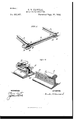
- Figure 1 is a perspective view of my improved railway-tie
- Fig. 2 is a similar view in detail of one of the end pieces and part of the cross-piece.
- A is an overhanging or projecting oifset at each end of the cross-piece A, adapted to receive the flange of the track-rail.
- these ofisets A are preferably formed by cutting away the end of the head of the rail, as shown at A and making an undercut in the offset formed by the end of the remaining portion of the head of the rail, as is shown in Fig. 2, so as to form the overhanging or undercut offset A of proper shape to receive the flange of the track-rail.
- This con struetion gives greater strength to the undercut offset, which thus possesses the thickness of the metal of the rail-head, and the head of the rail formsa strengthening-rib for the crosspiece.
- end pieces B are the end pieces, which are provided with longitudinal slots B to receive the ends of the cross-pieces A. These slots are preferably of an inverted-T shape, as shown, to receive the T-shaped cross-piece.
- the end pieces are provided with suitable bolt-holes d d, which register with bolt-holes cl (1' in the ends of the cross-pieces. By means of bolts D D, passed through the holes d d and d d, the end pieces B B and the cross-piece A may be bolted together.
- the 7 X are the track-rails, resting on the flat upper surface of the end pieces B B.
- the upper surfaces of the pieces B B may be formed with rabbets to receive rests G, of rubber, wood, or other suitable material.
- bracepiece B is a projecting or overhanging bracepiece on the top of the end piece B, adapted to receive the flange on the outer side of the rail.
- the rail X is clamped between the brace B of the end piece on its outer side and the oifset A of the cross-piece A on its inner side, the parts B and A fitting snugly over the outer and inner flanges, respectively.
- the rail is thus clamped firmly in place without the use of bolts or spikes.
- a metallic railway-tie consisting of two end pieces, each provided upon its outer side with a projecting overhanging brace to fit over the outer flange of the rail, and a connecting cross-piece adapted for connection at its ends with the end pieces and provided adjacent to each end with a projecting under cut ofiset adapted to fit over the inner flange of the rail and. located a substantial distance from the extreme end of the cross-piece.
- a wrought-iron cross-piece consisting of a section of a rail having the ends of the head portion cut away to form undercut projecting ofisets adjacent to the ends of the tie.
- a cast-iron end piece B having the inverted-T-shaped slot B and the integral overhanging brace-piece B and having its upper surface form ed with rabbets to receive a. rail-rest.
Landscapes
- Engineering & Computer Science (AREA)
- Architecture (AREA)
- Civil Engineering (AREA)
- Structural Engineering (AREA)
- Joining Of Building Structures In Genera (AREA)
Description
(No Model.)
0. B. MAONEAL.
METALLIC RAILWAY TIE.
No. 482,967. Patented Sept. 20, 1892.
- ww/emww f UNITED STATES PATENT OFFICE.
CHARLES B. MAONEAL, OF PHILADELPHIA, PENNSYLVANIA.
M ETALLIC RAILWAY-Tl E.
SPECIFICATION forming part of Letters Patent N 0. 482,967, dated September 20, 1892.
Application filed February 19, 1892. Serial No. 422,167. (No model.)
To all whom it may concern:
Be it known that I, CHARLES E. MAONEAL, a citizen of the United States, residing at Philadelphia, in the county of Philadelphia and State of Pennsylvania, have invented certain new and useful Improvements in Metallic Railway-Ties; and I do declare the following to be a full, clear, and exact description of the invention, such as will enable others skilled in the art to which it appertains to make-and use the same, reference being had to the accompanying drawings, and to the letters of reference marked thereon, which form a part of this specification.
My invention relates to metallic railwayties; and it consists of certain improvements, which are fully set forth in the following specification and are shown in the accompanying drawings, which form a part thereof.
The object of my invention is to construct an improved metallic railway-tie which can be cheaply manufactured and which will admit of expeditious and secure adjustment of the rails.
A further object is to utilize for cross-pieces rails that have been discarded from use on the track. I do not limit myself, however, to the use of rails as cross-pieces.
In carrying out my invention I employ slotted end pieces having projecting braces to engage the fiange of the rail on one side and cross-pieces which are received in the slots of the end pieces and are provided with proj ecting ofisets to engage the flange of the rail on the other side. The top portion of the end pieces may be furnished with rabbets to contain rests of rubber or other yielding material for the base of the rail.
My invention also relates to the peculiar construction of the slotted end pieces, whereby they may be used with crosspieces formed of discarded rails, and to the construction of the cross-pieces, whereby they are adapted to be connected with the end pieces and to clamp the rails of the track.
In the drawings, Figure 1 is a perspective view of my improved railway-tie, and Fig. 2 is a similar view in detail of one of the end pieces and part of the cross-piece.
Ais the cross piece, which may be composed of an ordinary Trail.
A is an overhanging or projecting oifset at each end of the cross-piece A, adapted to receive the flange of the track-rail. When ordinary T-rails are employed for the crosspiece A,these ofisets A are preferably formed by cutting away the end of the head of the rail, as shown at A and making an undercut in the offset formed by the end of the remaining portion of the head of the rail, as is shown in Fig. 2, so as to form the overhanging or undercut offset A of proper shape to receive the flange of the track-rail. This con struetion gives greater strength to the undercut offset, which thus possesses the thickness of the metal of the rail-head, and the head of the rail formsa strengthening-rib for the crosspiece.
B are the end pieces, which are provided with longitudinal slots B to receive the ends of the cross-pieces A. These slots are preferably of an inverted-T shape, as shown, to receive the T-shaped cross-piece. The end pieces are provided with suitable bolt-holes d d, which register with bolt-holes cl (1' in the ends of the cross-pieces. By means of bolts D D, passed through the holes d d and d d, the end pieces B B and the cross-piece A may be bolted together.
7 X are the track-rails, resting on the flat upper surface of the end pieces B B. The upper surfaces of the pieces B B may be formed with rabbets to receive rests G, of rubber, wood, or other suitable material.
B is a projecting or overhanging bracepiece on the top of the end piece B, adapted to receive the flange on the outer side of the rail.
When the parts are put together, the rail X is clamped between the brace B of the end piece on its outer side and the oifset A of the cross-piece A on its inner side, the parts B and A fitting snugly over the outer and inner flanges, respectively. The rail is thus clamped firmly in place without the use of bolts or spikes.
While I prefer the details of construction that have been shown, I do not limit myself to them, as they may be varied without departing from the invention.
What I claim as new, and desire to secure by Letters Patent, is-
1. A metallic railway-tie consisting of two end pieces, each provided upon its outer side with a projecting overhanging brace to fit over the outer flange of the rail, and a connecting cross-piece adapted for connection at its ends with the end pieces and provided adjacent to each end with a projecting under cut ofiset adapted to fit over the inner flange of the rail and. located a substantial distance from the extreme end of the cross-piece.
2. In ametallic railway-tie, a wrought-iron cross-piece consisting of a section of a rail having the ends of the head portion cut away to form undercut projecting ofisets adjacent to the ends of the tie. I
3. In a metallic railway-tie, a cast-iron end piece B, having the inverted-T-shaped slot B and the integral overhanging brace-piece B and having its upper surface form ed with rabbets to receive a. rail-rest.
4:. In a metallic railway-tie, the combination of the end portions having inverted-T-shaped slots and bolt-holes in their sides and the overhanging braces on their upper surfaces, with cross-pieces having ends of an inverted- T-shaped cross-section to fit the slots of the end pieces and provided with bolt-holes and the bolts for securing the end pieces and crosspieces together.
In testimony whereof I affix my signature in presence of two witnesses.
CHARLES B. MACNEAL.
Witnesses:
T. HENRY SMITH, JAMES H. BELL.
Publications (1)
| Publication Number | Publication Date |
|---|---|
| US482967A true US482967A (en) | 1892-09-20 |
Family
ID=2551818
Family Applications (1)
| Application Number | Title | Priority Date | Filing Date |
|---|---|---|---|
| US482967D Expired - Lifetime US482967A (en) | Metallic railway-tie |
Country Status (1)
| Country | Link |
|---|---|
| US (1) | US482967A (en) |
-
0
- US US482967D patent/US482967A/en not_active Expired - Lifetime
Similar Documents
| Publication | Publication Date | Title |
|---|---|---|
| US126453A (en) | Improvement in railway ties | |
| US206416A (en) | Improvement in railway-tracks | |
| US744285A (en) | Metallic railway-tie. | |
| US385492A (en) | Vania | |
| US664042A (en) | Metallic railway-tie. | |
| US429127A (en) | Construction of side-bearing railway-tracks | |
| US803611A (en) | Metallic railway-tie. | |
| US673639A (en) | Metallic railroad-tie. | |
| US170537A (en) | Improvement in railway-frogs | |
| US429128A (en) | Construction of railway-tracks | |
| US188710A (en) | Improvement in railway chairs and ties | |
| US375852A (en) | Street-railway construction | |
| US841575A (en) | Rail-joint. | |
| US240987A (en) | Railway cross-tie | |
| US356609A (en) | William whartos | |
| US466942A (en) | Railroad-tie | |
| US1100378A (en) | Safety guard-rail for railroads. | |
| US202607A (en) | Improvement in railway-tracks | |
| US464054A (en) | Jacob c | |
| US384061A (en) | James j | |
| US503054A (en) | Metallic railway tie or sleeper | |
| US838738A (en) | Track-fastening. | |
| US434420A (en) | Charles a | |
| US127910A (en) | Improvement in construction of railways | |
| US835325A (en) | Railway-track rail. |