US482746A - Cultivator - Google Patents
Cultivator Download PDFInfo
- Publication number
- US482746A US482746A US482746DA US482746A US 482746 A US482746 A US 482746A US 482746D A US482746D A US 482746DA US 482746 A US482746 A US 482746A
- Authority
- US
- United States
- Prior art keywords
- handles
- wings
- cultivator
- bar
- brace
- Prior art date
- Legal status (The legal status is an assumption and is not a legal conclusion. Google has not performed a legal analysis and makes no representation as to the accuracy of the status listed.)
- Expired - Lifetime
Links
- 238000010276 construction Methods 0.000 description 6
- 238000003756 stirring Methods 0.000 description 2
- VVNCNSJFMMFHPL-VKHMYHEASA-N D-penicillamine Chemical compound CC(C)(S)[C@@H](N)C(O)=O VVNCNSJFMMFHPL-VKHMYHEASA-N 0.000 description 1
- 229940075911 depen Drugs 0.000 description 1
- 238000004519 manufacturing process Methods 0.000 description 1
Images
Classifications
-
- A—HUMAN NECESSITIES
- A01—AGRICULTURE; FORESTRY; ANIMAL HUSBANDRY; HUNTING; TRAPPING; FISHING
- A01B—SOIL WORKING IN AGRICULTURE OR FORESTRY; PARTS, DETAILS, OR ACCESSORIES OF AGRICULTURAL MACHINES OR IMPLEMENTS, IN GENERAL
- A01B63/00—Lifting or adjusting devices or arrangements for agricultural machines or implements
- A01B63/02—Lifting or adjusting devices or arrangements for agricultural machines or implements for implements mounted on tractors
- A01B63/023—Lateral adjustment of their tools
Definitions
- This invention relates to new and useful improvements in cultivators; and it consists in the peculiar construction of a frame carrying the cultivator-teeth and having side wings which may be adjusted to and from the middle to increase or decrease the width of the track of the cultivator, and, further, in the peculiar construction of an extensible brace between such side wings and the frame, whereby the rigidity of the frame is maintained at all times.
- the invention further consists in the peculiar construction of a frame, whereby the auxiliary teeth or tooth may be added when the frame is extended to more thoroughly stir up the ground at all points in the track of the cultivator.
- the invention furtherconsists in the peculiar construction, arrangement, and combination of the various parts, all as more fully hereinafter described.
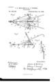
- Figure l is a plan view of a cultivator embodying our improvements.
- Fig. 2 is a side elevation thereof.
- Fig. 3 is a detached perspective view of the brace.
- A is the central bar of the frame, at the forward end of which is a bracket B, to which are pivoted the wings or side bars D.
- K is a notched segment upon the bar A at the base of the lever I,with which the sprin gcatch L is adapted to engage, a suitable handle M being formed to operate said springcatch upon the handle of the lever I.
- M are the cnltivator-teeth, which .are secured upon the side wings D, and also one 0r more of them may be secured upon the bar A.
- This brace we preferably construct as follows: a are vertical standards secured upon the handles E and preferably adjustable thereon by means of the bolt h, engaging in the slot c.
- This standard at its lower end is provided with a lateral offset d, having a bolt or pin e, engaging in a link f, which extends horizontally therefrom.
- This link is provided with a slot g, extending almost its entire length and engaging with a pin or bolt h upon vertical standards t', secured upon the wings D, the whole construction being such that as the wings D are moved inward the bolt or pin 7L will move along the slot g in the linkrf.
- this horizontal link is interposed between two vertical standards gives us a brace between the handle and wing which is rigid at all times and which will adjust itself automatically to any position of the wings.
- This movement is permitted by virtue of the elongated slot in link f, which allows one of the pins to move substantially the length of the slot, and by arranging the link f horizontal and the standards ,vertical with their ends connected to the liigk any downward movement is prevented, ut a lateral IOO movement allowed.
- the bar A is provided with a rearward extension N, upon which the auxiliary frames or arms O are adapted to be secured by means of the clamping-bolts P, so that in case the wings are extended to their utmost, if it is desired to thoroughly cover the ground, we may put on these auxiliary arms, carrying suitable cultivator-teeth preferably arranged to track between the teeth on the frame.
- hinged side bars having laterally-adjusting means, and adjustable braces connecting the handles and side bars, consisting of projecting members on the handles and projecting members on the side bars, and a loosely-held sliding member uniting the projecting member, substantially as described.
- a cultivator the combination, with a center bar and handles mounted thereon, of hinged side bars having adjusting means and braces connecting the handles and side bars, consisting of fixed depen ding standards on the handles having horizontal offsets, fixed standards on the side bars having horizontal oifsets, and horizon tal slotted links loosely secured to the offsets and uniting the same, substantially as described.
Landscapes
- Life Sciences & Earth Sciences (AREA)
- Soil Working Implements (AREA)
- Engineering & Computer Science (AREA)
- Mechanical Engineering (AREA)
- Soil Sciences (AREA)
- Environmental Sciences (AREA)
Description
( No Model-) J. G. MALLERY 8v E. J. YOUNGS. GULTIVATOR.
No. 482,746. Patented Sept. 20, 1892.
[7m/@wrd Wo-MQ/Ss'es Y Cf n?? Jwm/@s jl/Zwl my Il'wrrnn Srarns PATENT Genion.
JAMES G. MALLERY AND EDIVIN J. YOUN GS, OF FLINT, ASSIGNORS, BY DIRECT AND MESNE ASSIGNMENTS, TO THE GALE MANUFACTURING COMPANY,
F ALBION, MICHIGAN.
CU LTIVATOR.
SPECIFICATION forming part of Letters Patent No. 482,746, dated September 20, 1892.
` Application tied october 19,1891. satana-109.193. (No model.)
To @ZZ whom t may concern:
Be it known that we, JAMES G. MALLERY and EDWIN J. YOUNGS, citizens of the United States, residing at Flint, in the county of Genesee and State of Michigan, have invented certain new and useful Improvements in Cultivators, of which the following is a specification, reference being had therein to the accompanying drawings.
This invention relates to new and useful improvements in cultivators; and it consists in the peculiar construction of a frame carrying the cultivator-teeth and having side wings which may be adjusted to and from the middle to increase or decrease the width of the track of the cultivator, and, further, in the peculiar construction of an extensible brace between such side wings and the frame, whereby the rigidity of the frame is maintained at all times.
The invention further consists in the peculiar construction of a frame, whereby the auxiliary teeth or tooth may be added when the frame is extended to more thoroughly stir up the ground at all points in the track of the cultivator.
The invention furtherconsists in the peculiar construction, arrangement, and combination of the various parts, all as more fully hereinafter described.
In the drawings, Figure l is a plan view of a cultivator embodying our improvements. Fig. 2 is a side elevation thereof. Fig. 3 is a detached perspective view of the brace.
A is the central bar of the frame, at the forward end of which is a bracket B, to which are pivoted the wings or side bars D.
E are the handles, which at their lower ends are secured to the central barA and are supported intermediately upon the bar by means of the braces F.
G are toggle -levers connected with the outer ends of the wings D at one end and with the block II, which is slidingly secured on the bar A at the other end. This block is moved backward and forward upon the bar A by means of the lever I, pivoted at the rear end of the bar A and connected with the block I-I by means of the connecting-rod J.
K is a notched segment upon the bar A at the base of the lever I,with which the sprin gcatch L is adapted to engage, a suitable handle M being formed to operate said springcatch upon the handle of the lever I.
M are the cnltivator-teeth, which .are secured upon the side wings D, and also one 0r more of them may be secured upon the bar A.
Where it is desired to cultivate but a narrow track and to thoroughly stir up the ground, the operator may by pushing the handle I forward to the position shown in Fig. 2, draw in the wings D, the toggle-levers G being drawn inwardly by the sliding forward of the block H. The latch L engaging into the segment K will hold these Wings in their adjusted position. In such a cultivator having adjustable side wings it has been found difficult to brace the handles and constant trouble arises from the fact that the support for such handles must be entirely from the bar A. In order to form a brace which will at all times give a rigid frame and a good support for the handles, we employ a construction which embodies a brace supporting the handles against lateral movement at all times and at the same time extensible with the movement of said wings. This brace we preferably construct as follows: a are vertical standards secured upon the handles E and preferably adjustable thereon by means of the bolt h, engaging in the slot c. This standard at its lower end is provided with a lateral offset d, having a bolt or pin e, engaging in a link f, which extends horizontally therefrom. This link is provided with a slot g, extending almost its entire length and engaging with a pin or bolt h upon vertical standards t', secured upon the wings D, the whole construction being such that as the wings D are moved inward the bolt or pin 7L will move along the slot g in the linkrf. The fact that this horizontal link is interposed between two vertical standards gives us a brace between the handle and wing which is rigid at all times and which will adjust itself automatically to any position of the wings. This movement is permitted by virtue of the elongated slot in link f, which allows one of the pins to move substantially the length of the slot, and by arranging the link f horizontal and the standards ,vertical with their ends connected to the liigk any downward movement is prevented, ut a lateral IOO movement allowed. We preferably so construct the brace that the link fmay rotate upon its pivot ein the inward motion of the wings D, as plainly shown in dotted lines in Fig. l.
The bar A is provided with a rearward extension N, upon which the auxiliary frames or arms O are adapted to be secured by means of the clamping-bolts P, so that in case the wings are extended to their utmost, if it is desired to thoroughly cover the ground, we may put on these auxiliary arms, carrying suitable cultivator-teeth preferably arranged to track between the teeth on the frame.
What we claim as our invention is 1. In a cultivator, the combination, with a central bar and handles supported thereon, of hinged side bars Ahaving laterally-adjusting means, and adjustable braces connecting the side bars and handles, consisting of two fixed vertical members and a slotted horizontal member between and slidingly attached to the fixed members, substantially as described.
2. In a cultivator, the combination, with a central bar and handles supported thereon, of
hinged side bars having laterally-adjusting means, and adjustable braces connecting the handles and side bars, consisting of projecting members on the handles and projecting members on the side bars, and a loosely-held sliding member uniting the projecting member, substantially as described.
3. ln a cultivator, the combination, with a center bar and handles mounted thereon, of hinged side bars having adjusting means and braces connecting the handles and side bars, consisting of fixed depen ding standards on the handles having horizontal offsets, fixed standards on the side bars having horizontal oifsets, and horizon tal slotted links loosely secured to the offsets and uniting the same, substantially as described. Y
In testimony whereof we affix oursgnatures in presence of two witnesses.
JAMES G. MALLERY. EDWIN J. YOUNGS. Witnesses:
JAMES H. MGFARLAN, J. M. RUSSELL.
Publications (1)
| Publication Number | Publication Date |
|---|---|
| US482746A true US482746A (en) | 1892-09-20 |
Family
ID=2551597
Family Applications (1)
| Application Number | Title | Priority Date | Filing Date |
|---|---|---|---|
| US482746D Expired - Lifetime US482746A (en) | Cultivator |
Country Status (1)
| Country | Link |
|---|---|
| US (1) | US482746A (en) |
-
0
- US US482746D patent/US482746A/en not_active Expired - Lifetime
Similar Documents
| Publication | Publication Date | Title |
|---|---|---|
| US638769A (en) | Harrow. | |
| US233379A (en) | Cultivator | |
| US954197A (en) | Lawn-swing. | |
| US345903A (en) | Field-weeder | |
| US756255A (en) | Harrow. | |
| US583914A (en) | little | |
| US701844A (en) | Weeder attachment for cultivators. | |
| US1019382A (en) | Cultivator. | |
| US704515A (en) | Seat for cultivators. | |
| US258305A (en) | Combined wheelbarrow and cultivator | |
| US542614A (en) | Office | |
| US644096A (en) | Combined vibrating harrow and roller. | |
| US226448A (en) | Half of his eight to stewaet d | |
| US210861A (en) | Improvement in cultivators | |
| US93651A (en) | Improvement in cultivators | |
| US508398A (en) | Harrow for listed corn | |
| US329707A (en) | Cultivator | |
| US772232A (en) | Cultivator. | |
| US424946A (en) | Cultivator | |
| US701007A (en) | Cultivator. | |
| US665751A (en) | Harrow. | |
| US409605A (en) | Cultivator | |
| US438989A (en) | Cultivator | |
| US400467A (en) | Yielding shovel for cultivators | |
| US331413A (en) | Wheel cultivator and furrower |