US4826636A - Multi-level film fill industrial cross flow water cooling tower - Google Patents
Multi-level film fill industrial cross flow water cooling tower Download PDFInfo
- Publication number
- US4826636A US4826636A US07/100,916 US10091687A US4826636A US 4826636 A US4826636 A US 4826636A US 10091687 A US10091687 A US 10091687A US 4826636 A US4826636 A US 4826636A
- Authority
- US
- United States
- Prior art keywords
- pack
- fill pack
- fill
- film
- feet
- Prior art date
- Legal status (The legal status is an assumption and is not a legal conclusion. Google has not performed a legal analysis and makes no representation as to the accuracy of the status listed.)
- Expired - Lifetime
Links
- XLYOFNOQVPJJNP-UHFFFAOYSA-N water Substances O XLYOFNOQVPJJNP-UHFFFAOYSA-N 0.000 title claims abstract description 94
- 238000001816 cooling Methods 0.000 title claims abstract description 31
- 238000009826 distribution Methods 0.000 claims abstract description 20
- 239000000463 material Substances 0.000 claims description 6
- 230000001939 inductive effect Effects 0.000 claims 1
- 238000010276 construction Methods 0.000 abstract description 3
- 238000012360 testing method Methods 0.000 description 14
- 238000009434 installation Methods 0.000 description 6
- 125000006850 spacer group Chemical group 0.000 description 5
- 240000005020 Acaciella glauca Species 0.000 description 3
- 238000013461 design Methods 0.000 description 3
- 230000009977 dual effect Effects 0.000 description 3
- 238000004519 manufacturing process Methods 0.000 description 3
- 235000003499 redwood Nutrition 0.000 description 3
- 230000003466 anti-cipated effect Effects 0.000 description 2
- 230000002860 competitive effect Effects 0.000 description 2
- 238000011156 evaluation Methods 0.000 description 2
- 239000008235 industrial water Substances 0.000 description 2
- 238000011068 loading method Methods 0.000 description 2
- 239000004033 plastic Substances 0.000 description 2
- 229920003023 plastic Polymers 0.000 description 2
- 229920003002 synthetic resin Polymers 0.000 description 2
- 239000000057 synthetic resin Substances 0.000 description 2
- 238000012546 transfer Methods 0.000 description 2
- 239000002023 wood Substances 0.000 description 2
- 241000220317 Rosa Species 0.000 description 1
- WYTGDNHDOZPMIW-RCBQFDQVSA-N alstonine Natural products C1=CC2=C3C=CC=CC3=NC2=C2N1C[C@H]1[C@H](C)OC=C(C(=O)OC)[C@H]1C2 WYTGDNHDOZPMIW-RCBQFDQVSA-N 0.000 description 1
- 238000013459 approach Methods 0.000 description 1
- 230000000712 assembly Effects 0.000 description 1
- 238000000429 assembly Methods 0.000 description 1
- 230000002939 deleterious effect Effects 0.000 description 1
- 230000000694 effects Effects 0.000 description 1
- 230000002349 favourable effect Effects 0.000 description 1
- 238000009432 framing Methods 0.000 description 1
- 230000003993 interaction Effects 0.000 description 1
- 230000000670 limiting effect Effects 0.000 description 1
- 238000000034 method Methods 0.000 description 1
- 238000005457 optimization Methods 0.000 description 1
- 230000002829 reductive effect Effects 0.000 description 1
- 230000000717 retained effect Effects 0.000 description 1
- 230000003068 static effect Effects 0.000 description 1
- 238000006467 substitution reaction Methods 0.000 description 1
- 238000013022 venting Methods 0.000 description 1
Images


Classifications
-
- F—MECHANICAL ENGINEERING; LIGHTING; HEATING; WEAPONS; BLASTING
- F28—HEAT EXCHANGE IN GENERAL
- F28C—HEAT-EXCHANGE APPARATUS, NOT PROVIDED FOR IN ANOTHER SUBCLASS, IN WHICH THE HEAT-EXCHANGE MEDIA COME INTO DIRECT CONTACT WITHOUT CHEMICAL INTERACTION
- F28C1/00—Direct-contact trickle coolers, e.g. cooling towers
- F28C1/04—Direct-contact trickle coolers, e.g. cooling towers with cross-current only
-
- Y—GENERAL TAGGING OF NEW TECHNOLOGICAL DEVELOPMENTS; GENERAL TAGGING OF CROSS-SECTIONAL TECHNOLOGIES SPANNING OVER SEVERAL SECTIONS OF THE IPC; TECHNICAL SUBJECTS COVERED BY FORMER USPC CROSS-REFERENCE ART COLLECTIONS [XRACs] AND DIGESTS
- Y02—TECHNOLOGIES OR APPLICATIONS FOR MITIGATION OR ADAPTATION AGAINST CLIMATE CHANGE
- Y02B—CLIMATE CHANGE MITIGATION TECHNOLOGIES RELATED TO BUILDINGS, e.g. HOUSING, HOUSE APPLIANCES OR RELATED END-USER APPLICATIONS
- Y02B30/00—Energy efficient heating, ventilation or air conditioning [HVAC]
- Y02B30/70—Efficient control or regulation technologies, e.g. for control of refrigerant flow, motor or heating
-
- Y—GENERAL TAGGING OF NEW TECHNOLOGICAL DEVELOPMENTS; GENERAL TAGGING OF CROSS-SECTIONAL TECHNOLOGIES SPANNING OVER SEVERAL SECTIONS OF THE IPC; TECHNICAL SUBJECTS COVERED BY FORMER USPC CROSS-REFERENCE ART COLLECTIONS [XRACs] AND DIGESTS
- Y02—TECHNOLOGIES OR APPLICATIONS FOR MITIGATION OR ADAPTATION AGAINST CLIMATE CHANGE
- Y02P—CLIMATE CHANGE MITIGATION TECHNOLOGIES IN THE PRODUCTION OR PROCESSING OF GOODS
- Y02P80/00—Climate change mitigation technologies for sector-wide applications
- Y02P80/10—Efficient use of energy, e.g. using compressed air or pressurized fluid as energy carrier
-
- Y—GENERAL TAGGING OF NEW TECHNOLOGICAL DEVELOPMENTS; GENERAL TAGGING OF CROSS-SECTIONAL TECHNOLOGIES SPANNING OVER SEVERAL SECTIONS OF THE IPC; TECHNICAL SUBJECTS COVERED BY FORMER USPC CROSS-REFERENCE ART COLLECTIONS [XRACs] AND DIGESTS
- Y10—TECHNICAL SUBJECTS COVERED BY FORMER USPC
- Y10S—TECHNICAL SUBJECTS COVERED BY FORMER USPC CROSS-REFERENCE ART COLLECTIONS [XRACs] AND DIGESTS
- Y10S261/00—Gas and liquid contact apparatus
- Y10S261/11—Cooling towers
Definitions
- This invention broadly relates to a crossflow cooling tower having two or more film fill packs located in vertically and horizontally offset relationship to each other, with a water distribution system which divides the water to be cooled into separate streams which are directed to respective upper water inlets of the packs.
- the invention includes the discovery that there are certain critical parameters for the relative dimensions of the film fill packs so that the effectiveness of the tower can be optimized; specifically, the height of each pack, the length of air travel through the pack and the inclination of the upright air inlet face of each pack should be within certain specific limits.
- the multi-level fill pack arrangement is especially advantageous as a replacement for splash type fill structure in an existing tower, and has been found to provide a substantial improvement in the duty of the tower.
- the first or installed cost of the tower including the splash bar contruction was of primary concern to the engineer during design of such towers, by virtue of the fact that relatively low electrical energy costs for powering the mechanically driven fans did not significantly enter into the overall equation of tower costs when initial as well as operating costs were calculated over the anticipated useful life of the tower.
- One alternative to constructing a new tower as a replacement for an existing unit is to change out the fill structure in order to provide a more cost effective means of bringing the hot water to be cooled into sensible and evaporative heat exchange relationship with cooling air directed through the tower by the associated fan structure.
- the fill structure must be more efficient than in the existing tower if the reconstruction is to be justified when operating costs are taken into account.
- Film fill structure has the potential of providing a more efficient operating package than splash type fill in the same cubic space, but film fill has normally been associated only with package and smaller commercial installations because of the higher initial cost of film fill.
- U.S. Pat. No. 4,548,766 dated Oct. 22, 1985 and assigned to the assignee of the present invention discloses a film fill pack constructed of a series of side-by-side vacuum formed film fill sheets.
- the fill sheets illustrated and described in U.S. Pat. No. 4,548,766 each have outwardly extending spacers which are complementally received in notches of spacers of the adjacent sheets in order to maintain the sheets in required horizontally spaced relationship.
- a single film fill sheet pack is not normally a suitable direct substitution for the splash bars in the air-water interchange area of a larger industrial mechanical draft crossflow water cooling tower.
- One problem in this regard is that if the length of the fill pack is increased to accommodate a larger volume of water to be cooled, the increased cooling effectiveness of the film fill pack is such that a large part the heat transfer between the descending water and the crossflowing currents of air occurs within upper reaches of the fill pack, and a much smaller proportion of heat transfer takes place in the lower regions of the same.
- One possible solution might be to increase the width of a film fill pack in an industrial crossflow cooling tower in an effort to improve the overall effectiveness of the tower.
- the hot water to be cooled could be distributed over a wider area in order to proportionately reduce the thickness of the water films descending over the sheets.
- such a solution would not overcome the problem of improving the cooling effectiveness of the fill pack within lower regions of the same.
- the increased horizontal dimension of the film fill pack would have a deleterious effect on static air pressure drop through the fill assembly and in the end, decrease the effectiveness of the film fill.
- the addition of film fill to extend the width may not be cost effective if the cooling air has expended much of its cooling potential prior to entering the additional fill.
- the film fill is more expensive than a series of splash bars in the same space, it is not cost effective to place film fill throughout the entire area that would normally be occupied by splash bars.
- a crossflow water cooling tower is provided with at least two separate packs of film fill located at different elevations within the tower framing and disposed in horizontally offset relationship relative to each other. It has been discovered that the multi-level film fill cooling tower provides superior thermal performance when each of the film fill packs is of dimensions within a range of certain critical parameters.
- optimization of the cooling effectiveness of the multi-level film fill cooling tower can be achieved by limiting the height of each fill pack to a value within the range of 10 feet to 32 feet, and providing horizontally extending air passageways through the pack of an overall length in the range of three feet to eight feet.
- each of the fill packs should be inclined in the range of about 4° to about 7° relative to vertical.
- a water distribution system directs separate streams of hot water to respective distribution basins lying atop a corresponding film fill pack. For instance, when two separate film fill packs of approximately equal height, equal width and equal length are provided within the air-water interchange section of a mechanical draft tower, the distribution system is constructed to divide the hot water to be cooled into streams having substantially equal flow rates which are delivered to the upper water inlets of repsective film fill packs. In cases where the film fill packs are not of equal height, water loadings may be adjusted accordingly so that the temperature of the cold water discharged from the lower end of each pack is essentially the same.
- the present invention is particularly applicable for reconstruction and revitalization of older towers originally provided with a splash-type fill.
- An increase in cooling effectiveness of approximately 10-30% has been observed in practice after replacement of splash bar fill with multilevel film fill packs constructed in accordance with the invention.
- FIG. 1 is a fragmentary, elevational view of an industrial, mechanical draft water cooling tower with parts broken away in section to depict a multi-level film fill pack arrangement of the present invention which in this instance is comprised of two vertically and horizontally offset fill packs located on each side of the tower;
- FIG. 2 is a reduced view somewhat similar to FIG. 1 but showing the disposition of the two film fill packs within the framework of a somewhat larger tower;
- FIG. 3 is a view of a tower similar in size to the tower depicted in FIG. 2 and shows a fill pack arrangement wherein two overlapping packs are separated by an intermediate bay presented by the tower framework;
- FIG. 4 is an illustration of a multi-level film fill pack arrangement in accordance with the invention within framework of a tower somewhat larger in size than the towers depicted in FIGS. 1-3;
- FIG. 5 is a view of a tower similar to the tower shown in FIG. 4 except that the fill packs are taller and are separated by an intermediate bay of the tower framework;
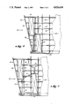
- FIG. 6 is an illustration of a multi-level film fill pack tower in accordance with the invention having framework somewhat smaller than the framework of the tower shown in FIG. 4;
- FIG. 7 is a view somewhat similar to FIG. 6 except that the fill pack arrangement comprises three staggered, offset packs each of a height smaller than the film fill packs illustrated in FIG. 6;
- FIG. 8 is a graphical representation of for exemplary test data showing the total height of fill necessary to achieve equivalent cooling of the water at various water flow rates, and including a comparison of results obtained using a multi-level film fill pack arrangement in accordance with the invention as opposed to a single film fill pack;
- FIG. 9 is a perspective, fragmentary view of the three level film fill pack arrangement depicted in FIG. 7 and a water distribution system therefor, with the outline of the tower being depicted in dashed lines.
- the industrial mechanical draft crossflow water cooling tower depicted therein is broadly designated by the numeral 20 and includes a framework 22 that rests atop a cold water collection basin 24.
- a fan 26 (FIG. 1) is driven by a motor 28 to draw currents of air into a central plenum of the tower 20 and discharge the air in a generally vertical direction through fan cylinder 30.
- the following description of the invention is also applicable to hyperbolic or natural draft towers in addition to the tower 20 of mechanical draft type as is illustrated in the drawings for exemplary purposes only.
- the framework 22 of the tower 20 comprises a number of spaced, vertical columns 32 that are crossed by horizontal transverse girts 34 which, in turn, are located above and carried by longitudinal girts 36 that extend in a horizontal direction perpendicular to the girts 34.
- a number of sloped columns 38 extend in an upright direction at an angle from vertical across an air inlet 40 located at the side of tower 20.
- Opposed sidewalls of the tower 20 are closed by casing panels 42 in the case of an opposed airflow tower as shown in FIG. 1; three sidewalls are provided for a single air inlet tower.
- fill structure for each air-water interchange section 43 of the tower 20 includes a first film fill pack 44 and a second film fill pack 46.
- Each of the packs 44, 46 is comprised of a series of thin, vertically extending sheets of material disposed in face to face relationship to each other and presenting a number of air passageways between the sheets for the flow of air therethrough in a direction from the air inlet 40 and toward a central plenum 45 of tower 20.
- the formed sheets of the packs 44, 46 preferably each present a repeating chevron pattern defining a series of zig-zag, serpentine, spaced ridges on opposed faces of the sheet with ridges on one face of the sheet defining grooves in an opposite face thereof and vice versa.
- the sheets of the film fill packs 44, 46 are similar to the film fill sheets described and illustrated in the aforementioned U.S. Pat. No. 4,548,766 in that each of the sheets is formed with a plurality of integral spacers which project in opposite directions from each sheet and which have notches that receive outer portions of the spacers of the next adjacent sheet so that the sheets are maintained in required horizontally spaced relationship relative to each other.
- each of the packs 44, 46 is comprised of two separate, slightly spaced assemblies of film fill sheets, with an outer pack assembly having sheets presenting formed air inlet louvers along an outer edge 48 and the other pack assembly having sheets presenting formed, inclined drift eliminators 50 along an inner edge.
- Integral, horizontally extending corrugated sections 52 of each sheet cooperate with the same sections of adjacent sheets to distribute hot water over a central, chevron-patterned air-water contact zone 54 while also assisting in maintaining the requisite sheet spacing.
- the dual pack assembly of each pack 44, 46 is described in more detail in co-pending application Ser. No. 07/069,377 filed July 2, 1987 entitled "Plastic Fill Sheet for Water Cooling Tower with Air Guiding Sheet Spacers" and assigned to the assignee of the present invention.
- synthetic resin film material is available to permit fabrication of the fill pack as a one piece assembly instead of dual packs 44, 46 as illustrated, equal results may be obtained.
- the first film fill pack 44 is laterally offset (i.e., in a horizontal direction) from the second film fill pack 46 and is disposed at a higher elevation than the elevation of the second pack 46. Furthermore, a hot water distribution system 56 directs essentially separate streams of hot water to be cooled to each pack 44, 46 in order to attain greater overall cooling effectiveness in comparison to, for instance, a tower having a single film fill pack assembly extending completely along the vertical extent of the air inlet.
- the water distribution system 56 includes a main inlet header pipe 58 (FIG. 1) that is connected by means of one or more transverse conduits 59 having control valve 61 therein to a parallel somewhat smaller secondary conduit 60.
- a number of upstanding, horizontally spaced pipes 62 coupled to the secondary conduit 60 direct hot water received from inlet header pipe 58 to respective horizontally spaced splash boxes 64 disposed along the length of a hot water distribution basin 66 defined by the floor 67 of basin 66, and the transversely extending upright walls 69 and 71 respectively.
- the wall 69 is added to restrict the overall size of the hot water distribution basin, which is normally delineated in part by the outermost upright wall 73.
- Water distribution nozzles within apertures in the floor portion 67 of the basin 66 function to uniformly disperse water over the upper water inlet face of the first film fill pack 44.
- the orifices normally provided in the outboard section of the hot water distribution basin between walls 69 and 73 are plugged to preclude flow of hot water therethrough.
- a plurality of angled, horizontally spaced downcomer pipes 68 are also coupled to the secondary conduit 60 between and spaced from adjacent pairs of the upstanding pipes 62.
- the downcomer pipes 68 each function to direct hot water to be cooled to a one of a number of corresponding splash boxes 70 that are located within a second hot water distribution basin 72 below basin 66 and commensurate in longitudinal length with the latter.
- basin 72 defined by the bottom floor 75 and upright end walls 77 and 79 respectively is carried by the columns 32a and 32b of FIG. 1 at a position intermediate hot water basin 66 and the underlying cold water basin 24.
- Each of the upstanding pipes 62 as well as the downcomer pipes 68 is advantageously provided with a venting device so that hot water discharged from the secondary conduit 60 is split into streams with essentially equal flow rates and any effects of siphoning are substantially precluded. In this manner, the flow rates of water directed to each of the distribution basins 66, 72 are essentially equal and the resultant heads of water on the nozzles of each basin 66, 72 are thereby uniform.
- the main inlet header 58 was of a size ranging from 48 inches to 60 inches in diameter
- the secondary conduit 60 was 16 inches in diameter
- the pipes 62, 68 were of a diameter ranging from six to eight inches.
- Water descending through the first film pack 44 is discharged at the lower end thereof into a cold water collection sub-basin 74 (FIGS. 1-6) which is elevated with respect to the main cold water collection basin 24.
- One or more drain pipes 76 communicate with the sub-basin 74 for directing the cooled water to the main cold water basin 24.
- Water descending through the second film fill pack 46 is also discharged directly into the cold water collection basin 24 and mixes with the cold water exiting the drain pipes 76.
- each of the film fill packs 44, 46 when constructed and arranged in a particular manner provides superior results in comparison to splash fill structures conventionally used in mechanical draft crossflow water cooling towers. More particularly, each of the film fill packs 44, 46 present air passageways which begin at the air inlet face 78 thereof and terminate at the air outlet face near eliminators 50 thereof. These passageways have a horizontal dimension in the range of about three feet to about eight feet in length. Better results have been observed, however, when the air passageways are of a horizontal length ranging from about four feet to about seven feet while best results have been observed when the air passageways are of a length in the range of about 4.75 feet to about 6.75 feet. The air passageways extend in a generally horizontal direction in transverse relationship to the direction of the travel of the water descending through the respective film fill packs 44, 46.
- each of the film fill packs 44, 46 is inclined in the range of about 4° degrees to about 7° relative to vertical. Better results are attained, though, when the inclination of the air inlet face 78 relative to vertical is in the range of about 4.75° to 5.5°.
- each film fill pack 44, 46 is in the range of about 10 feet to abut 32 feet. Better results are realized, however, when the vertical projected height of each fill pack 44, 46 is in the range of about 12 feet to about 21 feet.
- L.N.F. and A.T refers to the fact that the lineal net feet of the fill pack and the air travel through the fill packs was held constant.
- the terms "lineal net feet” in this sense is the equivalent to the overall length of the fill packs (i.e. in a direction perpendicular to the plane of the page in FIGS. 1-7 minus the lengths of any portions of the fill pack that are adjacent an obstruction (such as an upright column) which significantly blocks the flow of air through that portion of the fill packs.
- a film fill pack arrangement comprised of two separate, vertically and horizontally offset lifts or packs provides superior performance in comparison to fill structure of a single film fill pack when the total projected or nominal height of the fill packs is in the range of 20 feet to about 60 feet.
- the nominal or total projected fill height is the sum of the projected height of each fill pack 44, 46 which in the case of FIG. 1 is a distance greater than the projected vertical extent of both packs 44, 46 combined due to the overlapping relationship of the same.
- the upper set of curves depicted in FIG. 8 correspond to data obtained during tests conducted for a natural draft tower.
- the air travel distance or length of air passageways (A.T.) through the pack was held constant at a value of 6.75 feet, and again other factors such as the temperature of the incoming hot water and the wet bulb temperature of the incoming air were fixed.
- A.T. air travel distance or length of air passageways
- the notation "Const. H.T. and L.N.F.” refers to the fact that the overall height of the tower was held constant, and that the lineal net feet of the fill packs was held constant.
- FIGS. 1-6 A comparison of FIGS. 1-6 provides insight as to the placement of the fill fill packs 44, 46 within the tower 20 in accordance with the size and disposition of the framework 22 of the latter.
- the packs 44, 46 are located in adjacent bays bttween the columns 32 in slightly overlapping relationship.
- An inclined baffle 80 between the lower inboard corner of fill pack 46 and the upper outboard corner of pack 46 precludes air flowing past the upper part of pack 46 in bypassing relationship.
- the baffle may be a vertical panel in the plane of the adjacent column 32a (FIG. 1) extending between the cold water basin 74 therebelow.
- FIG. 2 depicts placement of the film fill packs 44, 46 within framework 22 that is equal in height but somewhat larger in horizontal dimension than the framework 22 depicted in FIG. 1.
- the downcomer pipes 68 serving the second film fill pack 46 in FIG. 2 are straight in contrast to the angled configuration of the downcomer pipes 68 provided for the fill pack arrangement depicted in FIG. 1.
- the configuration of FIG. 2 should include an upright baffle (not shown) presenting air from bypassing the upper part of the full pack 46 as shown in FIG. 2.
- the tower framework 22 is essentially the same size as the framework 22 depicted in FIG. 2, but in this case the projected height of each pack 44, 46 is greater than the height of the corresponding packs 44, 46 in either of FIGS. 1 or 2.
- the packs 44, 46 in FIG. 3 are separated by an intermediate bay, and an inclined baffle 80 is provided to substantially prevent bypassing of air. It has been found that the inclination of the baffle 80 should be less than 45° from horizontal so that the flow of air into the tower 20 is not substantially impeded.
- the tower 20 illustrated in FIG. 4 has framework 22 of a height greater than the corresponding framework 22 shown in FIG. 3, although the packs 44, 46 located in adjacent bays of the tower 20 of FIG. 4 are a height equal to the height of the packs 44, 46 shown in FIG. 3.
- the height of the packs 44, 46 is greater than the height of the corresponding packs 44, 46 shown in FIG. 4 while the framework 22 of FIG. 5 is substantially identical in size to the size of the framework 22 illustrated in FIG. 4.
- the packs 44, 46 in FIG. 5 are separated by an intermediate bay defined by columns 32 to enable air to flow in unimpeded fashion through all regions of the packs 44, 46; also, baffle 80 is provided to substantially preclude bypassing air through the vacant bay and around the packs 44, 46.
- the tower 20 depicted in FIG. 6 has framework 22 of equal height but of somewhat smaller horizontal dimension than the framework 22 shown in FIG. 5.
- the height of the packs 44, 46 is equal to the height of the packs 44, 46 shown in FIG. 4.
- the packs 44, 46 in FIG. 6 are located away from the tower inlet face 40 next to the sloped columns 38 in similar orientation to the disposition of the packs 44, 46 shown in FIG. 1.
- the multi-level film fill cooling tower 20 illustrated in FIG. 7 includes first and second film fill packs 44, 46 as well as a third film fill pack 82 disposed below packs 44, 46 and above main cold water collection basin 24.
- Each of the fill packs 44, 46, 82 are vertically and horizontally offset from each other and present a total projected vertical height and air passageways of dimensions within the aforementioned critical ranges. Also, each of the packs 44, 46, 82 is inclined from vertical to a degree within the critical ranges set forth above.
- the hot water distribution system 56 of the tower 20 shown in FIG. 7 is more fully illustrated in FIG. 9.
- the pipes 62 serving the hot water distribution basin 66 overlying the first film fill pack 44 are of an angular configuration while the downcomer pipes 68 serving the hot water distribution basin 72 for the second film fill pack 46 are straight.
- a third set of downcomer pipes 84 located between adjacent pairs of the pipes 62 and the pipes 68, direct water to splash boxes 86 (shown only in FIG. 9) which in turn are located within a third hot water distribution basin 88 lying atop the third film fill pack 82.
- Water discharged from the third film fill pack 82 exits directly into the main cold water collection basin 24, and a second cold water collection sub-basin 90 is provided immediately below the second film fill pack 46 for receiving water from the latter and directing the same through drain pipes 92 into the main cold water collection basin 24.
- the heights of the film fill packs so that, for instance, the first film fill pack presents a projected height greater than the second film fill pack 46.
- water loadings on the respective packs are adjusted so that the temperatures of the cold water discharged from the respective packs are approximately equal.
- the drift eliminator structure normally provided adjacent splash type fill structure is not needed and may be removed during installation of the multi-level fill pack arrangement in an existing tower framework, since the packs 44, 46 are provided with integral drift eliminator structure along edges 50.
- the external air inlet louvers along air inlet face 40 may optionally be retained for aesthetic purposes.
Landscapes
- Engineering & Computer Science (AREA)
- Mechanical Engineering (AREA)
- General Engineering & Computer Science (AREA)
- Heat-Exchange Devices With Radiators And Conduit Assemblies (AREA)
- Separation By Low-Temperature Treatments (AREA)
Abstract
Description
Claims (11)
Priority Applications (1)
| Application Number | Priority Date | Filing Date | Title |
|---|---|---|---|
| US07/100,916 US4826636A (en) | 1987-09-25 | 1987-09-25 | Multi-level film fill industrial cross flow water cooling tower |
Applications Claiming Priority (1)
| Application Number | Priority Date | Filing Date | Title |
|---|---|---|---|
| US07/100,916 US4826636A (en) | 1987-09-25 | 1987-09-25 | Multi-level film fill industrial cross flow water cooling tower |
Publications (1)
| Publication Number | Publication Date |
|---|---|
| US4826636A true US4826636A (en) | 1989-05-02 |
Family
ID=22282189
Family Applications (1)
| Application Number | Title | Priority Date | Filing Date |
|---|---|---|---|
| US07/100,916 Expired - Lifetime US4826636A (en) | 1987-09-25 | 1987-09-25 | Multi-level film fill industrial cross flow water cooling tower |
Country Status (1)
| Country | Link |
|---|---|
| US (1) | US4826636A (en) |
Cited By (12)
| Publication number | Priority date | Publication date | Assignee | Title |
|---|---|---|---|---|
| US4934663A (en) * | 1989-09-20 | 1990-06-19 | Phelps Peter M | Cooling tower with sloping high density film fill sandwiched between low density film fill |
| US5028356A (en) * | 1987-07-10 | 1991-07-02 | Vincent Wiltz | Multi-level film fill assembly cooling tower |
| FR2658906A1 (en) * | 1990-02-23 | 1991-08-30 | Hamon | Method for cooling a liquid in an atmospheric cooler (cooling tower) and cooler for implementing this method |
| US5283012A (en) * | 1993-03-15 | 1994-02-01 | The Marley Cooling Tower Company | Self-balancing hot water distribution system for multi-level cooling tower |
| US5427718A (en) * | 1994-02-22 | 1995-06-27 | Phelps; Peter M. | Upper and lower crossflow film fill stack for a cooling tower |
| US5569415A (en) * | 1995-09-18 | 1996-10-29 | Phelps; Peter M. | Cross-flow cooling tower with reduced upper inboard fill section |
| US5925291A (en) * | 1997-03-25 | 1999-07-20 | Midwest Research Institute | Method and apparatus for high-efficiency direct contact condensation |
| US6460832B1 (en) | 2000-08-11 | 2002-10-08 | The Marley Cooling Tower Company | Nested, expandable, liquid film fill sheet bundle for expedited installation as a film fill pack |
| US20030098515A1 (en) * | 2001-11-26 | 2003-05-29 | Smith Kenyon P. | Heat transfer core for water cooling tower |
| US20050051916A1 (en) * | 2003-09-08 | 2005-03-10 | C.E. Shepherd Co., Inc. | Cooling media pack |
| US20050120688A1 (en) * | 2003-12-08 | 2005-06-09 | C.E. Shepherd Co., Inc. | Drift eliminator, light trap, and method of forming same |
| KR20150018669A (en) | 2013-08-08 | 2015-02-24 | 서종대 | Multi-stage cross flow type cooling towers |
Citations (4)
| Publication number | Priority date | Publication date | Assignee | Title |
|---|---|---|---|---|
| US3764121A (en) * | 1969-09-11 | 1973-10-09 | Marley Co | Hyperbolic cross flow cooling tower with basins and fill integrated into shell |
| US3820353A (en) * | 1972-11-09 | 1974-06-28 | Japan Gasoline | Evaporative cooling apparatus |
| US4317785A (en) * | 1981-02-20 | 1982-03-02 | The Marley Company | Water cooling tower having combination splash and film fill structure |
| US4548766A (en) * | 1984-05-07 | 1985-10-22 | Marley Cooling Tower Company | Vacuum formable water cooling tower film fill sheet with integral spacers |
-
1987
- 1987-09-25 US US07/100,916 patent/US4826636A/en not_active Expired - Lifetime
Patent Citations (4)
| Publication number | Priority date | Publication date | Assignee | Title |
|---|---|---|---|---|
| US3764121A (en) * | 1969-09-11 | 1973-10-09 | Marley Co | Hyperbolic cross flow cooling tower with basins and fill integrated into shell |
| US3820353A (en) * | 1972-11-09 | 1974-06-28 | Japan Gasoline | Evaporative cooling apparatus |
| US4317785A (en) * | 1981-02-20 | 1982-03-02 | The Marley Company | Water cooling tower having combination splash and film fill structure |
| US4548766A (en) * | 1984-05-07 | 1985-10-22 | Marley Cooling Tower Company | Vacuum formable water cooling tower film fill sheet with integral spacers |
Cited By (17)
| Publication number | Priority date | Publication date | Assignee | Title |
|---|---|---|---|---|
| US5028356A (en) * | 1987-07-10 | 1991-07-02 | Vincent Wiltz | Multi-level film fill assembly cooling tower |
| US4934663A (en) * | 1989-09-20 | 1990-06-19 | Phelps Peter M | Cooling tower with sloping high density film fill sandwiched between low density film fill |
| FR2658906A1 (en) * | 1990-02-23 | 1991-08-30 | Hamon | Method for cooling a liquid in an atmospheric cooler (cooling tower) and cooler for implementing this method |
| AU665150B2 (en) * | 1993-03-15 | 1995-12-14 | Marley Cooling Tower Company, The | Cooling tower water distribution |
| US5283012A (en) * | 1993-03-15 | 1994-02-01 | The Marley Cooling Tower Company | Self-balancing hot water distribution system for multi-level cooling tower |
| WO1994021366A1 (en) * | 1993-03-15 | 1994-09-29 | The Marley Cooling Tower Company | Cooling tower water distribution |
| US5770117A (en) * | 1994-02-22 | 1998-06-23 | Phelps; Peter M. | Upper and lower crossflow film fill stack for a cooling tower |
| US5427718A (en) * | 1994-02-22 | 1995-06-27 | Phelps; Peter M. | Upper and lower crossflow film fill stack for a cooling tower |
| US5569415A (en) * | 1995-09-18 | 1996-10-29 | Phelps; Peter M. | Cross-flow cooling tower with reduced upper inboard fill section |
| US5925291A (en) * | 1997-03-25 | 1999-07-20 | Midwest Research Institute | Method and apparatus for high-efficiency direct contact condensation |
| US6460832B1 (en) | 2000-08-11 | 2002-10-08 | The Marley Cooling Tower Company | Nested, expandable, liquid film fill sheet bundle for expedited installation as a film fill pack |
| US20030098515A1 (en) * | 2001-11-26 | 2003-05-29 | Smith Kenyon P. | Heat transfer core for water cooling tower |
| US6886816B2 (en) | 2001-11-26 | 2005-05-03 | Kenyon P. Smith | Heat transfer core for water cooling tower |
| US20050051916A1 (en) * | 2003-09-08 | 2005-03-10 | C.E. Shepherd Co., Inc. | Cooling media pack |
| US20050120688A1 (en) * | 2003-12-08 | 2005-06-09 | C.E. Shepherd Co., Inc. | Drift eliminator, light trap, and method of forming same |
| US7105036B2 (en) | 2003-12-08 | 2006-09-12 | C. E. Shepherd Co., Inc. | Drift eliminator, light trap, and method of forming same |
| KR20150018669A (en) | 2013-08-08 | 2015-02-24 | 서종대 | Multi-stage cross flow type cooling towers |
Similar Documents
| Publication | Publication Date | Title |
|---|---|---|
| US6070860A (en) | Crossflow water cooling tower having structure allowing air flow through water distribution system | |
| AU729162B2 (en) | Dry-air-surface heat exchanger | |
| US4826636A (en) | Multi-level film fill industrial cross flow water cooling tower | |
| CA2174564C (en) | Combination direct and indirect closed circuit evaporative heat exchanger with blow-through fan | |
| US4076771A (en) | Bottom vented wet-dry water cooling tower | |
| US4801410A (en) | Plastic fill sheet for water cooling tower with air guiding spacers | |
| US3322409A (en) | Water control apparatus for crossflow cooling tower | |
| KR930000655B1 (en) | Cooling apparatus | |
| US3925523A (en) | Opposed air path wet-dry cooling tower and method | |
| EP0357805B1 (en) | Four-way airflow induced draft crossflow cooling tower | |
| AU596941B2 (en) | Low silhouette cooling tower with trapezoidal fill and method of air flow therethrough | |
| CA2366889C (en) | Air mixing device having series of parallel airflow passages | |
| US4317785A (en) | Water cooling tower having combination splash and film fill structure | |
| US3784171A (en) | Evaporative heat exchange apparatus | |
| KR950011377B1 (en) | Splashbars, Fill Structures and Retainers in Evaporative Cooling Towers | |
| US4957276A (en) | Trapezoidal fill sheet for low silhouette cooling tower | |
| US5023022A (en) | Cooling tower with multiple fill sections of different types | |
| JPS6314277B2 (en) | ||
| JPH041271B2 (en) | ||
| CA2060531A1 (en) | Cooling tower with different resistance to gas flow | |
| AU2002310244B2 (en) | Evaporative cooler | |
| JPH0457959B2 (en) | ||
| HU219642B (en) | Body for increasing the intensification of heat and mass transfer between gas and liquid |
Legal Events
| Date | Code | Title | Description |
|---|---|---|---|
| AS | Assignment |
Owner name: MARLEY COOLING TOWER COMPANY, THE, 5800 FOXRIDGE D Free format text: ASSIGNMENT OF ASSIGNORS INTEREST.;ASSIGNORS:KINNEY, OHLER L. JR.;BUGLER, THOMAS W. III;REEL/FRAME:004807/0924 Effective date: 19870925 Owner name: MARLEY COOLING TOWER COMPANY, THE,KANSAS Free format text: ASSIGNMENT OF ASSIGNORS INTEREST;ASSIGNORS:KINNEY, OHLER L. JR.;BUGLER, THOMAS W. III;REEL/FRAME:004807/0924 Effective date: 19870925 |
|
| FEPP | Fee payment procedure |
Free format text: PAYOR NUMBER ASSIGNED (ORIGINAL EVENT CODE: ASPN); ENTITY STATUS OF PATENT OWNER: LARGE ENTITY |
|
| FEPP | Fee payment procedure |
Free format text: PETITION RELATED TO MAINTENANCE FEES GRANTED (ORIGINAL EVENT CODE: PMFG); ENTITY STATUS OF PATENT OWNER: LARGE ENTITY |
|
| REMI | Maintenance fee reminder mailed | ||
| FEPP | Fee payment procedure |
Free format text: PETITION RELATED TO MAINTENANCE FEES FILED (ORIGINAL EVENT CODE: PMFP); ENTITY STATUS OF PATENT OWNER: LARGE ENTITY |
|
| FPAY | Fee payment |
Year of fee payment: 4 |
|
| STCF | Information on status: patent grant |
Free format text: PATENTED CASE |
|
| SULP | Surcharge for late payment | ||
| FP | Lapsed due to failure to pay maintenance fee |
Effective date: 19930502 |
|
| FPAY | Fee payment |
Year of fee payment: 8 |
|
| FPAY | Fee payment |
Year of fee payment: 12 |
|
| AS | Assignment |
Owner name: CHASE MANHATTAN BANK, AS COLLATERAL AGENT, THE, TE Free format text: SECURITY AGREEMENT;ASSIGNOR:MARLEY COOLING TOWER COMPANY, THE;REEL/FRAME:012219/0126 Effective date: 20010710 |
|
| AS | Assignment |
Owner name: SPX COOLING TECHNOLOGIES, INC. (FORMERLY KNOWN AS Free format text: TERMINATION AND RELEASE OF SECURITY INTEREST IN PATENT RIGHTS (PREVIOUSLY RECORDED AT REEL 12219 FRAME 0126);ASSIGNOR:JPMORGAN CHASE BANK, N.A., AS COLLATERAL AGENT;REEL/FRAME:016851/0804 Effective date: 20051118 |