US4824288A - Culvert drainpipe system and method of use - Google Patents

Culvert drainpipe system and method of use Download PDF

Info

Publication number
US4824288A
US4824288A US07/206,519 US20651988A US4824288A US 4824288 A US4824288 A US 4824288A US 20651988 A US20651988 A US 20651988A US 4824288 A US4824288 A US 4824288A
Authority
US
United States
Prior art keywords
drainpipe
culvert
elements
plural
flow channels
Prior art date
Legal status (The legal status is an assumption and is not a legal conclusion. Google has not performed a legal analysis and makes no representation as to the accuracy of the status listed.)
Expired - Fee Related
Application number
US07/206,519
Inventor
Norie Naito
Current Assignee (The listed assignees may be inaccurate. Google has not performed a legal analysis and makes no representation or warranty as to the accuracy of the list.)
INTERPORT INTERNATIONAL A CA CORP
INTERPOT INTERNATIONAL
Original Assignee
INTERPOT INTERNATIONAL
Priority date (The priority date is an assumption and is not a legal conclusion. Google has not performed a legal analysis and makes no representation as to the accuracy of the date listed.)
Filing date
Publication date
Application filed by INTERPOT INTERNATIONAL filed Critical INTERPOT INTERNATIONAL
Priority to US07/206,519 priority Critical patent/US4824288A/en
Assigned to INTERPORT INTERNATIONAL, A CA. CORP. reassignment INTERPORT INTERNATIONAL, A CA. CORP. ASSIGNMENT OF ASSIGNORS INTEREST. Assignors: NAITO, NORIE
Application granted granted Critical
Publication of US4824288A publication Critical patent/US4824288A/en
Anticipated expiration legal-status Critical
Expired - Fee Related legal-status Critical Current

Links

Images

Classifications

    • EFIXED CONSTRUCTIONS
    • E02HYDRAULIC ENGINEERING; FOUNDATIONS; SOIL SHIFTING
    • E02BHYDRAULIC ENGINEERING
    • E02B11/00Drainage of soil, e.g. for agricultural purposes
    • YGENERAL TAGGING OF NEW TECHNOLOGICAL DEVELOPMENTS; GENERAL TAGGING OF CROSS-SECTIONAL TECHNOLOGIES SPANNING OVER SEVERAL SECTIONS OF THE IPC; TECHNICAL SUBJECTS COVERED BY FORMER USPC CROSS-REFERENCE ART COLLECTIONS [XRACs] AND DIGESTS
    • Y10TECHNICAL SUBJECTS COVERED BY FORMER USPC
    • Y10STECHNICAL SUBJECTS COVERED BY FORMER USPC CROSS-REFERENCE ART COLLECTIONS [XRACs] AND DIGESTS
    • Y10S138/00Pipes and tubular conduits
    • Y10S138/11Shape

Definitions

  • the present invention relates generally to subterranean drainage systems and more particularly to an improved culvert drainpipe and method of utilizing the same characterized by use of an elongate thin wall extruded drainpipe element formed having a generally S-shaped configuration and including plural curvilinear projections extending axially along the exterior of the element.
  • the present invention specifically addresses and alleviates the above-referenced need associated in the art by providing an improved subterranean drainage system. More particularly, an improved culvert drainpipe and method of utilizing the same is disclosed which is characterized by use of an elongate thin wall extruded drainpipe element
  • the drainpipe element is formed having a generally S-shaped configuration defining a pair of main flow channels therewithin and includes plural curvilinear C-shaped projections extending axially along the exterior of the element.
  • the distal edges of the drainpipe element define axially extending slits which serve to allow entry of ground water from the formation to flow into the main flow channels of the element and subsequently be removed from the formation.
  • the distal edges of the drainpipe element cooperate with one or more elongate wall extensions formed on the interior of the drainpipe element which prevent radial compression and/or collapse of the drainpipe element and additionally deter debris from entering into the main flow channels formed within the interior of the drainpipe element.
  • drainpipe elements are bundled together in a generally parallel axial orientation and are buried underground.
  • ground spring water and/or penetrated ground water contacts the bundled drainpipe elements, it is drawn by surface tension and gravity forces onto the exterior of the drainpipe element.
  • the accumulated water enters the interior of the drainpipe element to be disposed within the main flow channels by entry through the elongate axial slits formed adjacent the distal edges of the drainpipe element and may travel by gravity through the main flow channels of the element.
  • drainpipe element Due to the distal edges of the drainpipe element cooperating with one or more elongate wall extensions formed on the interior of the drainpipe element, radial compression and/or collapse of the drainpipe element is prohibited thereby insuring that the main flow channels remain substantially intact throughout prolonged duration.
  • the curvilinear projections formed on the exterior of the drainpipe element serve to maintain sufficient spacing between adjacent drainpipe elements maintained within the bundled configuration as well as serve as secondary flow channels for accumulated water drawn to the drainpipe elements.
  • the curvilinear extensions additionally serve to deter entry of debris from the formation, i.e. silt, rocks, and the like, into the main flow channels of each of the drainpipe elements, thereby insuring prolonged operational use.
  • the drainpipe element is formed of an extruded thin wall polyvinyl chloride (pvc) and/or acrylonitrile-butadiene-styrene (abs) material which resists environmental degregation for prolonged duration.
  • pvc polyvinyl chloride
  • ab acrylonitrile-butadiene-styrene
  • the present invention contemplates formation of the drainpipe elements having relatively long axial lengths, i.e. approximately 20 feet, which when bundled in a manner previously described may subsequently be abutted in an end-for-end orientation to have sufficient length for nearly all culvert drainage applications.
  • FIG. 1 is a perspective view of the drainpipe element of the present invention
  • FIG. 2 is a perspective view illustrating the bundling of multiple drainpipe elements in a generally parallel axial orientation preparatory to placing the same in a subterranean, application;
  • FIG. 3 depicts the bundled multiple drainpipe elements of FIG. 2 disposed within a subterranean culvert formation
  • FIG. 4 is a perspective view of multiple drainpipe elements juxtapositioned in multiple horizontal rows and placed within a concrete drainage culvert covered by a fiberglass mat;
  • FIG. 5 is a perspective view depicting the use of one differing sized drainpipe element disposed within a subterranean site utilized where large water flow applications are required.
  • the drainpipe element 10 comprises an elongate member formed having a generally S-shaped cross-sectional configuration.
  • the drainpipe element 10 is extruded as a thin walled elongate member from a plastic material, such as polyvinyl chloride (pvc) or acrylonitrile-butadiene-styrene polymer (abs), however other suitable materials having sufficient resistance to environmental degregation may be utilized.
  • a plastic material such as polyvinyl chloride (pvc) or acrylonitrile-butadiene-styrene polymer (abs), however other suitable materials having sufficient resistance to environmental degregation may be utilized.
  • pvc polyvinyl chloride
  • ab acrylonitrile-butadiene-styrene polymer
  • the drainpipe element 10 is formed having long axial length (i.e. approximately 20 feet) and a cross-sectional configuration which may vary depending upon applicational use.
  • the cross-sectional size comprises approximately one and one-half inches in maximum length. Due to the S-shaped configuration of the drainpipe element 10, a pair of main flow channels or voids 12 and 14 are formed within the interior of the drainpipe element 10 which, as will be explained in more detail infra, serve as the main flow conduit for water within the interior of the element 10.
  • the distal edges 16 and 18 of the element 10 are spaced through a short distance from the central wall portion 19 of element 10 and define axially extending slots 20A and 20B which serve as an inlet for ground water disposed upon the exterior of the element 10 to within a respective flow channel 12 and 14.
  • One or more wall extensions 22 are formed on opposite sides of the central wall portion 19 of the element 10 which straddle the distal edges 16 and 18 of the element 10. As may be recognized, the wall extensions 22 serve to capture the distal edges 16 and 18 of the element 10 and prevent the edges 16 and 18 from movement beyond the confines of the wall elements 22. As such, upon exertion of a compressive force against the drainpipe element 10, collapsing or substantial deformation of the thin wall of the drainpipe element 10 is prohibited thereby insuring the structural integrity of the flow channels 12 and 14.
  • the exterior surface of the drainpipe element 10 preferably includes plural curvilinear C-shaped channels 30 which extend axially throughout its length. Although in a preferred embodiment four of such curvilinear projections 30 are provided, those skilled in the art will recognize that variations in the number of the same are clearly contemplated herein.
  • the interior portion of each of the curvilinear projections 30 define an elongate aperture 32 which, as will be explained in more detail infra, serves as a secondary or auxiliary flow channel for the drainpipe element 10.
  • multiple drainpipe elements 10 are preferably bundled together in a parallel axial orientation by one or more ties 36.
  • the curvilinear projections 30 serve to maintain a small degree of spacing between adjacent drainpipe elements within the bundle.
  • the bundled drainpipe elements 10 are disposed within the interior of a culvert 40 formed in the earth formation and once positioned therewithin the culvert 40 may be filled with suitable water permeable substance, such as gravel and/or rocks 42 which facilitate filtered drainage of ground water and/or spring water therethrough and onto the bundled drainpipe elements 10.
  • suitable water permeable substance such as gravel and/or rocks 42 which facilitate filtered drainage of ground water and/or spring water therethrough and onto the bundled drainpipe elements 10.
  • multiple bundles of drainpipe elements 10 may be positioned in end-to-end orientation as desired.
  • the plural curvilinear projections 30 increase the external surface area of each of the drainpipe elements 10 and thereby serve to enhance the capability of the drainpipe 10 to accumulate ground water thereon. Further, it will be recognized that the curvilinear sections 30 additionally serve to maintain sufficient space between adjacent drainpipe elements 10 to deter compression of the individual drainpipe elements 10 within the bundle caused by the weight of the gravel 42 upon the bundled drainpipe elements 10. In addition, the curvilinear projections 30 help to prevent debris accumulation and clogging of the main flow channels 12 and 14 of the drainpipe element 10 by comprising small catch basins which serve to filter the ground water prior to entry into the main flow channels 12 and 14 thereby maintaining debris on the exterior surfaces only of the drainpipe elements 10.
  • the distal edges 16 and 18 of the drainpipe element 10 are urged toward the central wall portion 19 of the element 10.
  • the wall projections 22 serve to form a maze-like structure adjacent the axial inlets 20A and 20B forming the entrance into the main flow channels 12 and 14 which serves to deter the entry of silt, sand, and the like within the interior of the flow channels 12 and 14.
  • the drainpipe element 10 of the present invention is capable of remaining substantially free from debris obstructions during prolonged use.
  • drainpipe element 10 of the present invention an additional application of use of the drainpipe element 10 of the present invention is depicted.
  • multiple drainpipe elements 10 may be arranged in an abutted side-by-side orientation.
  • the distal edge 18 of each of the drainpipe elements 10 is positioned within the interior of the flow channel 12 formed in an adjacent one of the drainpipe elements 10 such that adjacent drainpipe elements 10 are maintained in an interlocked horizontal orientation.
  • multiple rows 10A, 10B, and 10C of the interlocked drainpipe elements 10 may be disposed within a concrete drain culvert or channel 50, as illustrated in FIG. 4.
  • the stacked rows 10A, 10B, and 10C of the multiple drainpipe elements 10 may then be covered with a suitable layer 52 or mat of fiberglass which prevents visual sight of the drainpipe members 10 from ground surface.
  • the fiberglass layer or mat 52 serves to filter ground water or the like accumulating thereon while allowing the passage of ground water to pass through the thickness of the mat 52 and contact the drainpipe elements 10. Upon contact, the ground water enters the interior flow channels 12 and 14 of the individual drainpipe elements 10 and is free to flow by gravity forces within the interior of the same.
  • FIG. 5 illustrates an additional embodiment of the present invention specifically adapted for applications requiring large flow rate drainage applications.
  • one or more of the drainpipe elements 10D is formed having an extremely large cross-sectional dimension whereby two large flow channels 12D and 14D are provided within the interior of the element 10D.
  • Multiple smaller sized drainpipe elements 10 may then be positioned about the exterior of the enlarged drainpipe element 10D and bundled together in a manner previously described.
  • the resultant bundled drainpipe elements 10 and 10D may then be positioned within a culvert 40 and covered with suitable gravel 42 in a manner described in relation to FIG. 3.

Landscapes

  • Engineering & Computer Science (AREA)
  • General Engineering & Computer Science (AREA)
  • Life Sciences & Earth Sciences (AREA)
  • Agronomy & Crop Science (AREA)
  • Mechanical Engineering (AREA)
  • Civil Engineering (AREA)
  • Structural Engineering (AREA)
  • Investigation Of Foundation Soil And Reinforcement Of Foundation Soil By Compacting Or Drainage (AREA)

Abstract

An improved culvert drainpipe and method of utilizing the same is disclosed characterized by use of an elongate thin wall extruded drainpipe element formed having a generally S-shaped configuration defining a pair of main flow channels and including plural curvilinear projections extending axially along the exterior of the element. The distal edges of the drainpipe element cooperate with one or more elongate wall extensions formed on the interior of the drainpipe element which prevent radial compression and/or collapse of the drainpipe element and deter debris from entering into the main the flow channels. In use, multiple drainpipe elements are bundled together in a generally parallel axis orientation whereby the curvilinear projections serve as secondary flow channels, improve debris segregation, and maintain space between adjacent drainpipe elements.

Description

FIELD OF USE
The present invention relates generally to subterranean drainage systems and more particularly to an improved culvert drainpipe and method of utilizing the same characterized by use of an elongate thin wall extruded drainpipe element formed having a generally S-shaped configuration and including plural curvilinear projections extending axially along the exterior of the element.
BACKGROUND OF THE INVENTION
As is well known, it is oftentimes necessary, if not desirable, to drain subterranean spring water and/or penetrated ground water from a particular geological site. Examples of the prior art drainage systems are numerous comprising such apparatus as perforated plastic tubes, concrete pipe with small apertures formed therein, bamboo pipe, gravel stones, and the like all of which have been used for culvert drainage applications Basically the required functions of such drainage systems are to initially draw water from the subterranean formation into the drainage system, subsequently provide a flow channel for the accumulated water through the drainage system, and preferably provide moderate resistance to geological concerns, such as degregation (i.e., decay) caused by the weight of the overburden upon the drainage system and clogging of the system through environmental debris buildup. Although nearly all of the prior art drainage systems heretofor utilized have proven generally effective when initially positioned within a formation, nearly all of the prior art systems have proved deficient in their ability to maintain their required function for prolonged periods of time. Primarily these deficiencies have been caused due to their inability to sufficiently resist internal debris buildup or degregation caused by exposure to the environment over prolonged time duration. As will be recognized, upon degregation or debris buildup, the removal and reinstallation of a substitute drainage system often proves difficult and extremely costly due to the fact that substantial overburden must be removed from the culvert prior to replacement of the same.
As such there exists a substantial need in the art for an improved culvert drainage system and method of use which functions to draw water from the subterranean formation, provides an unobstructed flow path for the accumulated ground water out of the formation, is capable of resisting degregation caused by prolonged exposure to environmental concerns, and resist debris buildup.
SUMMARY OF THE PRESENT INVENTION
The present invention specifically addresses and alleviates the above-referenced need associated in the art by providing an improved subterranean drainage system. More particularly, an improved culvert drainpipe and method of utilizing the same is disclosed which is characterized by use of an elongate thin wall extruded drainpipe element The drainpipe element is formed having a generally S-shaped configuration defining a pair of main flow channels therewithin and includes plural curvilinear C-shaped projections extending axially along the exterior of the element. The distal edges of the drainpipe element define axially extending slits which serve to allow entry of ground water from the formation to flow into the main flow channels of the element and subsequently be removed from the formation. The distal edges of the drainpipe element cooperate with one or more elongate wall extensions formed on the interior of the drainpipe element which prevent radial compression and/or collapse of the drainpipe element and additionally deter debris from entering into the main flow channels formed within the interior of the drainpipe element.
In use, multiple drainpipe elements are bundled together in a generally parallel axial orientation and are buried underground. As ground spring water and/or penetrated ground water contacts the bundled drainpipe elements, it is drawn by surface tension and gravity forces onto the exterior of the drainpipe element. Subsequently, the accumulated water enters the interior of the drainpipe element to be disposed within the main flow channels by entry through the elongate axial slits formed adjacent the distal edges of the drainpipe element and may travel by gravity through the main flow channels of the element.
Due to the distal edges of the drainpipe element cooperating with one or more elongate wall extensions formed on the interior of the drainpipe element, radial compression and/or collapse of the drainpipe element is prohibited thereby insuring that the main flow channels remain substantially intact throughout prolonged duration.
In addition, the curvilinear projections formed on the exterior of the drainpipe element serve to maintain sufficient spacing between adjacent drainpipe elements maintained within the bundled configuration as well as serve as secondary flow channels for accumulated water drawn to the drainpipe elements. The curvilinear extensions additionally serve to deter entry of debris from the formation, i.e. silt, rocks, and the like, into the main flow channels of each of the drainpipe elements, thereby insuring prolonged operational use.
In the preferred embodiment, the drainpipe element is formed of an extruded thin wall polyvinyl chloride (pvc) and/or acrylonitrile-butadiene-styrene (abs) material which resists environmental degregation for prolonged duration. In addition, the present invention contemplates formation of the drainpipe elements having relatively long axial lengths, i.e. approximately 20 feet, which when bundled in a manner previously described may subsequently be abutted in an end-for-end orientation to have sufficient length for nearly all culvert drainage applications.
DESCRIPTION OF THE DRAWINGS
These as well as other features of the present invention will become more apparent upon reference to the drawings wherein:
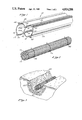
FIG. 1 is a perspective view of the drainpipe element of the present invention;
FIG. 2 is a perspective view illustrating the bundling of multiple drainpipe elements in a generally parallel axial orientation preparatory to placing the same in a subterranean, application;
FIG. 3 depicts the bundled multiple drainpipe elements of FIG. 2 disposed within a subterranean culvert formation;
FIG. 4 is a perspective view of multiple drainpipe elements juxtapositioned in multiple horizontal rows and placed within a concrete drainage culvert covered by a fiberglass mat; and
FIG. 5 is a perspective view depicting the use of one differing sized drainpipe element disposed within a subterranean site utilized where large water flow applications are required.
DESCRIPTION OF THE PREFERRED EMBODIMENTS
Referring to the figures, the improved culvert drainpipe element 10 and method of use is depicted. The drainpipe element 10 comprises an elongate member formed having a generally S-shaped cross-sectional configuration. Typically, the drainpipe element 10 is extruded as a thin walled elongate member from a plastic material, such as polyvinyl chloride (pvc) or acrylonitrile-butadiene-styrene polymer (abs), however other suitable materials having sufficient resistance to environmental degregation may be utilized. Preferably the drainpipe element 10 is formed having long axial length (i.e. approximately 20 feet) and a cross-sectional configuration which may vary depending upon applicational use. However in the preferred embodiment, the cross-sectional size comprises approximately one and one-half inches in maximum length. Due to the S-shaped configuration of the drainpipe element 10, a pair of main flow channels or voids 12 and 14 are formed within the interior of the drainpipe element 10 which, as will be explained in more detail infra, serve as the main flow conduit for water within the interior of the element 10.
The distal edges 16 and 18 of the element 10 are spaced through a short distance from the central wall portion 19 of element 10 and define axially extending slots 20A and 20B which serve as an inlet for ground water disposed upon the exterior of the element 10 to within a respective flow channel 12 and 14. One or more wall extensions 22 are formed on opposite sides of the central wall portion 19 of the element 10 which straddle the distal edges 16 and 18 of the element 10. As may be recognized, the wall extensions 22 serve to capture the distal edges 16 and 18 of the element 10 and prevent the edges 16 and 18 from movement beyond the confines of the wall elements 22. As such, upon exertion of a compressive force against the drainpipe element 10, collapsing or substantial deformation of the thin wall of the drainpipe element 10 is prohibited thereby insuring the structural integrity of the flow channels 12 and 14.
The exterior surface of the drainpipe element 10 preferably includes plural curvilinear C-shaped channels 30 which extend axially throughout its length. Although in a preferred embodiment four of such curvilinear projections 30 are provided, those skilled in the art will recognize that variations in the number of the same are clearly contemplated herein. The interior portion of each of the curvilinear projections 30 define an elongate aperture 32 which, as will be explained in more detail infra, serves as a secondary or auxiliary flow channel for the drainpipe element 10.
With the structure defined, the operation of and method of utilizing the improved drainpipe element 10 of the present invention may be described. With specific reference to FIG. 2, multiple drainpipe elements 10 are preferably bundled together in a parallel axial orientation by one or more ties 36. As will be recognized, during this bundling procedure, the curvilinear projections 30 serve to maintain a small degree of spacing between adjacent drainpipe elements within the bundle.
Subsequently, the bundled drainpipe elements 10 are disposed within the interior of a culvert 40 formed in the earth formation and once positioned therewithin the culvert 40 may be filled with suitable water permeable substance, such as gravel and/or rocks 42 which facilitate filtered drainage of ground water and/or spring water therethrough and onto the bundled drainpipe elements 10. As will be recognized, in order to meet the demands of the application, multiple bundles of drainpipe elements 10 may be positioned in end-to-end orientation as desired.
As the ground water and/or spring water travels through the gravel 42 by gravity forces, it contacts the bundled drainpipe elements 10 and adheres to the same via surface tension. The accumulated water subsequently enters into the flow channels 12 and 14 of each of the drainpipe elements 10 via the elongate slot openings 20A and 20B formed adjacent the distal edges 16 and 18 of the element 10. Once the water has entered into the main flow channels 12 and 14, the same is free to flow unobstructed through the flow channels 12 and 14 of each of the elements 10 and be removed from the culvert 40 via gravity forces.
As will be recognized, the plural curvilinear projections 30 increase the external surface area of each of the drainpipe elements 10 and thereby serve to enhance the capability of the drainpipe 10 to accumulate ground water thereon. Further, it will be recognized that the curvilinear sections 30 additionally serve to maintain sufficient space between adjacent drainpipe elements 10 to deter compression of the individual drainpipe elements 10 within the bundle caused by the weight of the gravel 42 upon the bundled drainpipe elements 10. In addition, the curvilinear projections 30 help to prevent debris accumulation and clogging of the main flow channels 12 and 14 of the drainpipe element 10 by comprising small catch basins which serve to filter the ground water prior to entry into the main flow channels 12 and 14 thereby maintaining debris on the exterior surfaces only of the drainpipe elements 10. Finally, it will be recognized that the interior apertures 32 formed within the interior of each of the curvilinear projections 30 serve as small secondary flow paths to conduct ground water along the length of the drainpipe elements 10 in a manner analogous to that described in relation to the main flow channels 12 and 14.
As will be recognized as compressive forces are exerted upon the drainpipe elements 10 from the weight of the gravel 42 and ground water accumulating thereon, the distal edges 16 and 18 of the drainpipe element 10 are urged toward the central wall portion 19 of the element 10. However, upon contact with the wall projections 22 formed on the central wall portion 19, further inward movement of the edges 16 and 18 is prevented, thereby insuring the structural integrity and maintenance of an unobstructed flow path within the main flow channels 12 and 14. Additionally, the wall projections 22 serve to form a maze-like structure adjacent the axial inlets 20A and 20B forming the entrance into the main flow channels 12 and 14 which serves to deter the entry of silt, sand, and the like within the interior of the flow channels 12 and 14. Thus, the drainpipe element 10 of the present invention is capable of remaining substantially free from debris obstructions during prolonged use.
Referring to FIG. 4, an additional application of use of the drainpipe element 10 of the present invention is depicted. As shown, multiple drainpipe elements 10 may be arranged in an abutted side-by-side orientation. Preferably in such an arrangement, the distal edge 18 of each of the drainpipe elements 10 is positioned within the interior of the flow channel 12 formed in an adjacent one of the drainpipe elements 10 such that adjacent drainpipe elements 10 are maintained in an interlocked horizontal orientation. Subsequently multiple rows 10A, 10B, and 10C of the interlocked drainpipe elements 10 may be disposed within a concrete drain culvert or channel 50, as illustrated in FIG. 4. The stacked rows 10A, 10B, and 10C of the multiple drainpipe elements 10 may then be covered with a suitable layer 52 or mat of fiberglass which prevents visual sight of the drainpipe members 10 from ground surface. As will be recognized, the fiberglass layer or mat 52 serves to filter ground water or the like accumulating thereon while allowing the passage of ground water to pass through the thickness of the mat 52 and contact the drainpipe elements 10. Upon contact, the ground water enters the interior flow channels 12 and 14 of the individual drainpipe elements 10 and is free to flow by gravity forces within the interior of the same.
FIG. 5 illustrates an additional embodiment of the present invention specifically adapted for applications requiring large flow rate drainage applications. In this embodiment, one or more of the drainpipe elements 10D is formed having an extremely large cross-sectional dimension whereby two large flow channels 12D and 14D are provided within the interior of the element 10D. Multiple smaller sized drainpipe elements 10 may then be positioned about the exterior of the enlarged drainpipe element 10D and bundled together in a manner previously described. The resultant bundled drainpipe elements 10 and 10D may then be positioned within a culvert 40 and covered with suitable gravel 42 in a manner described in relation to FIG. 3.
In such an embodiment, it will be recognized that the plural drainpipe elements 10 serve a filtering function for the main enlarged drainpipe element 10D which deters debris from entering into the main flow channels 12D and 14D of the enlarged drainpipe element 10D. As such, unrestricted flow of large volumes of water within the interior of the flow channels 12D and 14D is facilitated.
Although for purposes of description specific materials, sizes, and structures have been defined herein, those skilled in the art will recognize that various modifications to the same may be made without departing from the spirit of the present invention and such modifications are clearly contemplated herein.

Claims (15)

What is claimed is:
1. An improved culvert drainpipe comprising:
an elongate drainpipe element formed having a generally S-shaped cross-sectional configuration defining a pair of flow channels therein;
an axially extending inlet formed on each of said pair of flow channels;
a wall extension formed on said drainpipe element adjacent each inlet positioned to form an abutment for limiting movement of the distal edges of said drainpipe element; and
plural curvilinear extensions formed axially on the exterior of said drainpipe element.
2. The improved culvert drainpipe of claim 1 wherein said wall extension comprises a pair of wall extensions positioned on opposite sides of the distal edges of said drainpipe element.
3. The improved culvert drainpipe of claim 2 wherein said wall extensions extend outwardly beyond the distal edges of said drainpipe to shield the axially extending inlet formed on each of said pair of flow channels.
4. The improved culvert drainpipe of claim 3 wherein said plural curvilinear extensions are formed having a generally C-shaped cross-sectional configuration.
5. The improved culvert drainpipe of claim 4 wherein said drainpipe element comprises a thin-wall extruded drainpipe element.
6. The improved culvert drainpipe element of claim 5 wherein said drainpipe element is fabricated from a plastic material.
7. The improved culvert drainpipe element of claim 6 wherein said plastic material comprises polyvinyl-chloride.
8. The improved culvert drainpipe element of claim 6 wherein said plastic material comprises acrylonitrile-butadiene-styrene.
9. The improved culvert drainpipe element of claim 5 further comprising:
an assembly of plural drainpipe elements bundled together in a parallel orientation.
10. A method of forming a culvert drainage system comprising the steps of:
forming an elongate drainpipe element having a generally S-shaped cross-sectional configuration and including plural C-shaped extensions formed axially along the exterior surface of said drainpipe element;
bundling plural elongate elements together in a parallel orientation;
disposing said bundled elongate elements into a culvert; and
covering said bundled elongate elements with a water permeable filtering material.
11. The method of claim 10 wherein said covering step comprises covering said bundled elongate elements with gravel.
12. The method of claim 10 wherein said covering step comprises covering said bundled elongate elements with a fiberglass mat.
13. The method of claim 10 wherein said bundling step comprises the steps of:
arranging plural elongate elements in a parallel orientation defining a substantially circular cross-sectional configuration; and
tying said plural elongate elements together
14. The method of claim 10 wherein said bundling step comprises:
arranging plural elongate elements in an interconnected side-by-side orientation.
15. The method of claim 14 wherein said disposing step comprises vertically stacking plural interconnected side-by-side orientation elements in the culvert.
US07/206,519 1988-06-14 1988-06-14 Culvert drainpipe system and method of use Expired - Fee Related US4824288A (en)

Priority Applications (1)

Application Number Priority Date Filing Date Title
US07/206,519 US4824288A (en) 1988-06-14 1988-06-14 Culvert drainpipe system and method of use

Applications Claiming Priority (1)

Application Number Priority Date Filing Date Title
US07/206,519 US4824288A (en) 1988-06-14 1988-06-14 Culvert drainpipe system and method of use

Publications (1)

Publication Number Publication Date
US4824288A true US4824288A (en) 1989-04-25

Family

ID=22766758

Family Applications (1)

Application Number Title Priority Date Filing Date
US07/206,519 Expired - Fee Related US4824288A (en) 1988-06-14 1988-06-14 Culvert drainpipe system and method of use

Country Status (1)

Country Link
US (1) US4824288A (en)

Cited By (10)

* Cited by examiner, † Cited by third party
Publication number Priority date Publication date Assignee Title
US5305797A (en) * 1993-05-10 1994-04-26 Roy Sr John D Compartmented conduit tube construction
US5360291A (en) * 1991-06-27 1994-11-01 Miral Industries Co., Ltd. Method for laying cable or hose in channel and channel therefor
WO2003014484A1 (en) * 2001-08-10 2003-02-20 Advanced Drainage Systems, Inc. Pipe assembly for collecting surface water runoff and associated methods
US20060261194A1 (en) * 2003-01-27 2006-11-23 Rongwu Ding Conduit water-saving irrigating device with the conduit and its application
US20070253775A1 (en) * 2006-05-01 2007-11-01 Terratech Consulting Ltd. Culvert bundle for stream crossings and flow-through bridge abutments
US20080083175A1 (en) * 2003-12-16 2008-04-10 Andrew Niemczyk Method and device for improving drainage away from buildings
US20080210785A1 (en) * 2007-03-02 2008-09-04 Fu-Jen Hou Water feed pipe for use in irrigation
US20110064521A1 (en) * 2009-09-16 2011-03-17 Schafer Charles J Farmable water quality inlet for transporting water from surface to drainage pipe
US20160236877A1 (en) * 2013-10-03 2016-08-18 M-I L.L.C. Hose for bulk transfer operations
US20200284318A1 (en) * 2019-03-07 2020-09-10 Samwon Act Co., Ltd. Belt member and a cable guiding device comprising the same

Citations (8)

* Cited by examiner, † Cited by third party
Publication number Priority date Publication date Assignee Title
US1883468A (en) * 1930-07-12 1932-10-18 Metropolitan Paving Brick Comp Trickling filter floor construction
US1959633A (en) * 1932-03-19 1934-05-22 William J Madden Spacing member for multiple ducts
US3625258A (en) * 1970-03-16 1971-12-07 Warren Petroleum Corp Multipassage pipe
US4016727A (en) * 1974-03-18 1977-04-12 Fukuvi Chemical Industry Co., Ltd. Drain trough member and its connector
US4061272A (en) * 1975-06-20 1977-12-06 Winston Emanuel A Irrigation device
US4134268A (en) * 1977-10-06 1979-01-16 Jack G. Elmore Drainage field pipe
GB2040151A (en) * 1979-01-30 1980-08-28 Laing John Services Liquid channelling member
US4577998A (en) * 1981-10-22 1986-03-25 Imperial Chemical Industries, Plc Production of PVC irrigation pipe and the pipe so produced

Patent Citations (8)

* Cited by examiner, † Cited by third party
Publication number Priority date Publication date Assignee Title
US1883468A (en) * 1930-07-12 1932-10-18 Metropolitan Paving Brick Comp Trickling filter floor construction
US1959633A (en) * 1932-03-19 1934-05-22 William J Madden Spacing member for multiple ducts
US3625258A (en) * 1970-03-16 1971-12-07 Warren Petroleum Corp Multipassage pipe
US4016727A (en) * 1974-03-18 1977-04-12 Fukuvi Chemical Industry Co., Ltd. Drain trough member and its connector
US4061272A (en) * 1975-06-20 1977-12-06 Winston Emanuel A Irrigation device
US4134268A (en) * 1977-10-06 1979-01-16 Jack G. Elmore Drainage field pipe
GB2040151A (en) * 1979-01-30 1980-08-28 Laing John Services Liquid channelling member
US4577998A (en) * 1981-10-22 1986-03-25 Imperial Chemical Industries, Plc Production of PVC irrigation pipe and the pipe so produced

Cited By (14)

* Cited by examiner, † Cited by third party
Publication number Priority date Publication date Assignee Title
US5360291A (en) * 1991-06-27 1994-11-01 Miral Industries Co., Ltd. Method for laying cable or hose in channel and channel therefor
US5305797A (en) * 1993-05-10 1994-04-26 Roy Sr John D Compartmented conduit tube construction
WO2003014484A1 (en) * 2001-08-10 2003-02-20 Advanced Drainage Systems, Inc. Pipe assembly for collecting surface water runoff and associated methods
US6702517B2 (en) 2001-08-10 2004-03-09 Advanced Drainage Systems, Inc. Pipe assembly for collecting surface water runoff and associated methods
US20060261194A1 (en) * 2003-01-27 2006-11-23 Rongwu Ding Conduit water-saving irrigating device with the conduit and its application
US20080083175A1 (en) * 2003-12-16 2008-04-10 Andrew Niemczyk Method and device for improving drainage away from buildings
US20070253775A1 (en) * 2006-05-01 2007-11-01 Terratech Consulting Ltd. Culvert bundle for stream crossings and flow-through bridge abutments
US7559720B2 (en) * 2006-05-01 2009-07-14 Terratech Consulting Ltd. Culvert bundle for stream crossings and flow-through bridge abutments
US20080210785A1 (en) * 2007-03-02 2008-09-04 Fu-Jen Hou Water feed pipe for use in irrigation
US20110064521A1 (en) * 2009-09-16 2011-03-17 Schafer Charles J Farmable water quality inlet for transporting water from surface to drainage pipe
US20160236877A1 (en) * 2013-10-03 2016-08-18 M-I L.L.C. Hose for bulk transfer operations
US9994403B2 (en) * 2013-10-03 2018-06-12 M-I L.L.C. Hose for bulk transfer operations
US20200284318A1 (en) * 2019-03-07 2020-09-10 Samwon Act Co., Ltd. Belt member and a cable guiding device comprising the same
US11821491B2 (en) * 2019-03-07 2023-11-21 Samwon Act Co., Ltd. Belt member and a cable guiding device comprising the same

Similar Documents

Publication Publication Date Title
US7029208B1 (en) Biodegradable sediment barrier
DE69838712T2 (en) SYSTEM FOR COLLECTING LIQUIDS
US7074326B2 (en) Curb-and-grate inlet filter
US3830373A (en) Corrugated drainage tube with restraining screen
US4824288A (en) Culvert drainpipe system and method of use
US6709579B1 (en) Curb inlet filter
US4639165A (en) Drainage tube
US6368017B2 (en) Storm water detention filter system
US5120162A (en) Building foundation form with integral drain
US3753352A (en) Perforate conduit
US4793728A (en) Subsurface water drainage system
US4995759A (en) Drainage tube construction
US5316410A (en) Foundation drainage system
DE2237707A1 (en) DRAINAGE ELEMENT FOR EARTH AND GROUND HYDRAULIC ENGINEERING
US20050100412A1 (en) Drainage support apparatus
Johnson et al. Slit dam design for debris flow mitigation
US20030200707A1 (en) Building foundation form with integral drain
EP0952259B1 (en) Device for preventing flood and erosion damage
US7056057B2 (en) Fluid flows control apparatus and method of use
US20140294508A1 (en) Aggregate replacement
CA2930718C (en) A corrugated pipe having slits
KR20050111710A (en) Apparatus for channelling groundwater and the method therefor
JPH1037172A (en) Water pass cylinder for preventing ground liquefaction and burying method thereof
JP2556801B2 (en) How to prevent sand liquefaction and ground liquefaction
JPS5810758Y2 (en) Drainage devices such as embankments

Legal Events

Date Code Title Description
AS Assignment

Owner name: INTERPORT INTERNATIONAL, 200 NEWPORT CENTER DRIVE,

Free format text: ASSIGNMENT OF ASSIGNORS INTEREST.;ASSIGNOR:NAITO, NORIE;REEL/FRAME:004901/0850

Effective date: 19880601

Owner name: INTERPORT INTERNATIONAL, A CA. CORP.,CALIFORNIA

Free format text: ASSIGNMENT OF ASSIGNORS INTEREST;ASSIGNOR:NAITO, NORIE;REEL/FRAME:004901/0850

Effective date: 19880601

FPAY Fee payment

Year of fee payment: 4

REMI Maintenance fee reminder mailed
LAPS Lapse for failure to pay maintenance fees
FP Lapsed due to failure to pay maintenance fee

Effective date: 19970430

STCH Information on status: patent discontinuation

Free format text: PATENT EXPIRED DUE TO NONPAYMENT OF MAINTENANCE FEES UNDER 37 CFR 1.362