US4824195A - Monomode optical transmission fibre having a tapered end portion provided with a lens and method of manufacturing such a fibre - Google Patents
Monomode optical transmission fibre having a tapered end portion provided with a lens and method of manufacturing such a fibre Download PDFInfo
- Publication number
- US4824195A US4824195A US07/153,531 US15353188A US4824195A US 4824195 A US4824195 A US 4824195A US 15353188 A US15353188 A US 15353188A US 4824195 A US4824195 A US 4824195A
- Authority
- US
- United States
- Prior art keywords
- fibre
- end portion
- lens
- tapered end
- tapered
- Prior art date
- Legal status (The legal status is an assumption and is not a legal conclusion. Google has not performed a legal analysis and makes no representation as to the accuracy of the status listed.)
- Expired - Fee Related
Links
Images
Classifications
-
- G—PHYSICS
- G02—OPTICS
- G02B—OPTICAL ELEMENTS, SYSTEMS OR APPARATUS
- G02B6/00—Light guides; Structural details of arrangements comprising light guides and other optical elements, e.g. couplings
- G02B6/24—Coupling light guides
- G02B6/42—Coupling light guides with opto-electronic elements
- G02B6/4201—Packages, e.g. shape, construction, internal or external details
- G02B6/4202—Packages, e.g. shape, construction, internal or external details for coupling an active element with fibres without intermediate optical elements, e.g. fibres with plane ends, fibres with shaped ends, bundles
- G02B6/4203—Optical features
-
- G—PHYSICS
- G02—OPTICS
- G02B—OPTICAL ELEMENTS, SYSTEMS OR APPARATUS
- G02B6/00—Light guides; Structural details of arrangements comprising light guides and other optical elements, e.g. couplings
- G02B6/24—Coupling light guides
- G02B6/26—Optical coupling means
- G02B6/28—Optical coupling means having data bus means, i.e. plural waveguides interconnected and providing an inherently bidirectional system by mixing and splitting signals
- G02B6/2804—Optical coupling means having data bus means, i.e. plural waveguides interconnected and providing an inherently bidirectional system by mixing and splitting signals forming multipart couplers without wavelength selective elements, e.g. "T" couplers, star couplers
- G02B6/2856—Optical coupling means having data bus means, i.e. plural waveguides interconnected and providing an inherently bidirectional system by mixing and splitting signals forming multipart couplers without wavelength selective elements, e.g. "T" couplers, star couplers formed or shaped by thermal heating means, e.g. splitting, branching and/or combining elements
-
- G—PHYSICS
- G02—OPTICS
- G02B—OPTICAL ELEMENTS, SYSTEMS OR APPARATUS
- G02B6/00—Light guides; Structural details of arrangements comprising light guides and other optical elements, e.g. couplings
- G02B6/24—Coupling light guides
- G02B6/42—Coupling light guides with opto-electronic elements
- G02B6/4201—Packages, e.g. shape, construction, internal or external details
- G02B6/4219—Mechanical fixtures for holding or positioning the elements relative to each other in the couplings; Alignment methods for the elements, e.g. measuring or observing methods especially used therefor
- G02B6/4236—Fixing or mounting methods of the aligned elements
- G02B6/4244—Mounting of the optical elements
Definitions
- the invention relates to a monomode optical transmission fibre whose end portion has a tapered core and cladding, on which end portion a lens made of transparent material and having a spherical surface is arranged.
- the invention also relates to a method of manufacturing such a transmission fibre.
- the coupling efficiency is to be understood to mean the quotient of the radiation intensity received from the source by the transmission fibre and the total radiation intensity of this source.
- the coupling efficiency can be increased substantially by providing the tapered end portion of the monomode transmission fibre with a lens.
- this lens can be formed by immersing the tapered end portion of the fibre in a liquid transparent material, withdrawing the tapered end portion from the liquid material, and allowing the material which has adhered to the fibre end to solidify until a solid lens shape is formed.
- the refractice index of the lens material should be substantially higher than that of the core material, as a requirement to obtain an adequate numerical aperture for the combination of fibre end and lens. Owing to the large difference between the refractice index of the lens and that of the fibre core reflections at the lens-fibre interface may occur, which may give rise to feedback to the radiation source and a reduced coupling efficiency.
- the present invention provides a monomode transmission fibre having a tapered core and cladding and provided with a fused-on lens, which does not exhibit said reflections and which, surprisingly provides an adequate coupling efficiency.
- the monomode transmission fibre in accordance with the invention is characterized in that the lens is made of a material whose melting temperature is lower than that of the transmission fibre materials and whose refractive index is substantially equal to that of the core material.
- the refractive index of the lens material is substantially equal to that of the core material, the likelihood of feedback as a result of reflection from the lens-fibre interface is minimal.
- German Patent Specification No. 2,625,097 it is known per se from German Patent Specification No. 2,625,097 to arrange a lens on the end face of an optical transmission fibre, which lens is made of a material having a melting temperature which is lower than that of the fibre materials.
- the fibre described in said German Patent Specification is not a monomode fibre whose core has a tapered end portion but a multimode fibre having a straight core end portion.
- in the cladding should be removed partly from said fibre over a specific length by etching. This etching demands an additional process step.
- the etching liquid may affect other portions of the transmission fibre.
- the end face of the transmission fibre in accordance with German Patent Specification No. 2,625,097 on which the lens is to be arranged has a diameter larger than 50 ⁇ m.
- quartz glass is used for the fibre material and a soft glass is used for the lens material
- lens may become detached from the transmission fibre owing to the difference in expansion coefficients, particularly if the interface is relatively large.
- the diameter of the interface is between 15 and 30 ⁇ m, the risk of the lens becoming detached is substantially smaller.
- a preferred embodiment of the monomode transmission fibre is characterized further in that the lens material is glass.
- the outer surface of the lens is provided with an antireflection coating.
- a preferred embodiment of the transmission fibre is characterized further in that the length of the tapered end portion is of the order of magnitude of the diameter of the straight fibre portion.
- Such a transmission fibre has a better coupling efficiency than a transmission fibre whose tapered end portion is substantially longer.
- the lens may be arranged on a spherical end face of the tapered fibre.
- the lens is arranged on a flat end face of the tapered end portion of the transmission fibre.
- a monomode optical transmission fibre having a tapered end portion provided with a lens can be obtained by stretching a straight transmission fibre in an arc discharge until it fractures, subsequently immersing the tapered end portion in a liquid transparent material, withdrawing the tapered end portion from the liquid material and finally allowing the material which has adhered to the fibre end to solidify until a solid lens shape is obtained.
- the method in accordance with the invention is characterized in that the tapered end portion is immersed in a liquid transparent material whose melting temperature is lower than that of the fibre materials and whose refractive index is substantially equal to that of the fibre core.
- this end portion is provided with a flat end face.
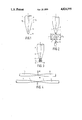
- FIG. 1 shows a known monomode transmission fibre having a tapered end portion
- FIG. 2 illustrates the inventive method of providing a fibre end with a lens
- FIG. 3 shows a preferred embodiment of a transmission fibre manufactured in accordance with this method
- FIG. 4 illustrates how a transmission fibre having a tapered end portion with a flat end face can be obtained.
- the transmission fibre 1 in FIG. 1 comprises a core 2 and a cladding 3.
- the refractive index of the core material differs slightly from that of the cladding material, so that most of the light which enters the fibre core can propagate through the core via the mechanism of total reflection from the core-to-cladding interfaces.
- the refractive index n 2 of the cladding material is for example 1.47 if this material is quartz, while the refractive index n, of the core material is, for example, approximately 0.3% higher.
- the present transmission fibre is a monomode fibre, which means that only radiation of a specific mode can propagate in the fibre core.
- the diameter of the core is substantially smaller than the diameter of the cladding.
- the one diameter is approximately 7 microns and the cladding diameter is approximately 125 microns.
- the greater part 4 of the transmission fibre is straight.
- the end portion 5 is tapered and has a spherical tip 6. This spherical tip is obtained automatically when a straight transmission fibre is stretched in arc discharge until the straight fibre fractures.
- the shape of the tapered end portion and the radius of the spherical tip 6 depend on the rate of stretching.
- the spherical tip has a radius of for example 12.5 microns and exhibits a lens action.
- a lens is arranged on the end portion 5 of the fibre, so that the effective entrance aperture of the fibre is enlarged.
- the portion 5 is given a flat end face 11, as shown in FIG. 2, and subsequently as is also shown in FIG. 2, the end portion 5 is immersed in a liquid or viscous material 7.
- the material 7 is a glass which has been melted in a crucible 8, as is schematically represented by the flame 9.
- Essential is that the temperature of the liquid glass is lower than the melting temperature of the fibre core or cladding, so that the fibre parameters have not changed after immersion.
- This glass may be for example of the type Bk1, Bk3 or TIk1.
- a type of glass must be chosen whose refractive index does not decrease substantially when it is softened and subsequently cooled.
- this material in the case of specific viscosity, will become drop-shaped, as indicated by the reference numeral 10 in FIG. 3.
- the dimension and shape of this drop can be influenced by the immersion depth and the temperature of the material 7 in the crucible 8.
- the fibre shown in FIG. 1, manufactured by means of the known method may be cut at a specific location of the tapered end portion 5.
- FIG. 4 schematically illustrates a method which is preferably used for obtaining a tapered transmission fibre having a flat end face.
- a straight transmission fibre is used which is first stretched over a specific length.
- a scratch 16 is formed by means of a scribing tool 15 of a circular scriber.
- the fibre 14 is stretched further until it fractures, the fracture surface being flat at the location of the scratch.
- two tapered fibres 4 having flat end faces are formed, as is shown in the lower part of FIG. 4.
- the straight transmission fibre When the straight transmission fibre is stretched it is possible to pull at both ends of this fibre. However, it has been found that better results are obtained if one end of the straight fibre is immobilized and the pulling force is applied to the other fibre end.
- the part which was immobilized has a substantially shorter tapered end portion (for example 125 micron) than the fibre part to which the pulling force was applied.
- the transmission fibre with a shorter tapered end portion has a higher coupling efficiency than a transmission fibre having a longer tapered end portion.
- the lens obtained in accordance with the method illustrated in FIG. 2 is made of a homogeneous material having a comparatively high refractive index.
- the surface of this lens may reflect a part of the incident light.
- an antireflection coating 13 may be applied to the outer surface 12 of the lens 10, as is shown in FIG. 3.
- a coupling efficiency of over 55% was obtained.
Landscapes
- Physics & Mathematics (AREA)
- General Physics & Mathematics (AREA)
- Optics & Photonics (AREA)
- Optical Couplings Of Light Guides (AREA)
- Optical Fibers, Optical Fiber Cores, And Optical Fiber Bundles (AREA)
- Diffracting Gratings Or Hologram Optical Elements (AREA)
Abstract
A monomode optical transmission fibre (1) is described, having a tapered end portion (5) on which a lens (10) is arranged. This lens is obtained by immersing the fibre end in a transparent liquid material (7) whose melting temperature is lower than that of the fibre materials and whose refractive index is substantially equal to that of the fibre core (2), and by allowing the drop which adheres to the fibre after withdrawal to solidify.
Description
This is a continuation of application Ser. No. 801,369, filed Nov. 25, 1985, now abandoned.
The invention relates to a monomode optical transmission fibre whose end portion has a tapered core and cladding, on which end portion a lens made of transparent material and having a spherical surface is arranged. The invention also relates to a method of manufacturing such a transmission fibre.
Such a transmission fibre and method are known from the article "Efficient Coupling Of Laser Diodes To Tapered Monomode Fibres With High-Index End" in Electronics Letters, vol. 19, no. 6, March 1983, pages 205-207. As described in this article, monomode transmission fibres with a tapered core and cladding, in comparison with transmission fibres with a straight and flat end portion, have substantially better properties as regards coupling efficiency, permissible offset of the fibre relative to a radiation source, which is for example a diode laser, and the feedback of radiation to the radiation source as a result of reflections inside the fibre.
The coupling efficiency is to be understood to mean the quotient of the radiation intensity received from the source by the transmission fibre and the total radiation intensity of this source.
As a result of the feedback effect a part of the radiation emitted by the diode laser can re-enter the diode laser. This feedback may give rise to an undesired modulation of the radiation emitted by the diode laser.
The coupling efficiency can be increased substantially by providing the tapered end portion of the monomode transmission fibre with a lens. As is described in the above mentioned article, this lens can be formed by immersing the tapered end portion of the fibre in a liquid transparent material, withdrawing the tapered end portion from the liquid material, and allowing the material which has adhered to the fibre end to solidify until a solid lens shape is formed. In said article it is stated that the refractice index of the lens material should be substantially higher than that of the core material, as a requirement to obtain an adequate numerical aperture for the combination of fibre end and lens. Owing to the large difference between the refractice index of the lens and that of the fibre core reflections at the lens-fibre interface may occur, which may give rise to feedback to the radiation source and a reduced coupling efficiency.
The present invention provides a monomode transmission fibre having a tapered core and cladding and provided with a fused-on lens, which does not exhibit said reflections and which, surprisingly provides an adequate coupling efficiency. The monomode transmission fibre in accordance with the invention is characterized in that the lens is made of a material whose melting temperature is lower than that of the transmission fibre materials and whose refractive index is substantially equal to that of the core material.
Since the refractive index of the lens material is substantially equal to that of the core material, the likelihood of feedback as a result of reflection from the lens-fibre interface is minimal.
It is to be noted that it is known per se from German Patent Specification No. 2,625,097 to arrange a lens on the end face of an optical transmission fibre, which lens is made of a material having a melting temperature which is lower than that of the fibre materials. However, the fibre described in said German Patent Specification is not a monomode fibre whose core has a tapered end portion but a multimode fibre having a straight core end portion. Before the lens is fused to the fibre in accordance with said German Patent Specification No. 2,625,097, in the cladding should be removed partly from said fibre over a specific length by etching. This etching demands an additional process step. Moreover, the etching liquid may affect other portions of the transmission fibre.
The end face of the transmission fibre in accordance with German Patent Specification No. 2,625,097 on which the lens is to be arranged has a diameter larger than 50 μm. When quartz glass is used for the fibre material and a soft glass is used for the lens material, lens may become detached from the transmission fibre owing to the difference in expansion coefficients, particularly if the interface is relatively large. In the case of the monomode transmission fibre in accordance with the invention, where the diameter of the interface is between 15 and 30 μm, the risk of the lens becoming detached is substantially smaller.
A preferred embodiment of the monomode transmission fibre is characterized further in that the lens material is glass.
Preferably, the outer surface of the lens is provided with an antireflection coating.
A preferred embodiment of the transmission fibre is characterized further in that the length of the tapered end portion is of the order of magnitude of the diameter of the straight fibre portion. Such a transmission fibre has a better coupling efficiency than a transmission fibre whose tapered end portion is substantially longer.
The lens may be arranged on a spherical end face of the tapered fibre. However, suitably the lens is arranged on a flat end face of the tapered end portion of the transmission fibre.
Another aspect of the invention concerns the method of manufacturing the monomode transmission fibre. As is described in said article in Electronics Letters, vol. 19, no. 6, p. 205-207, a monomode optical transmission fibre having a tapered end portion provided with a lens can be obtained by stretching a straight transmission fibre in an arc discharge until it fractures, subsequently immersing the tapered end portion in a liquid transparent material, withdrawing the tapered end portion from the liquid material and finally allowing the material which has adhered to the fibre end to solidify until a solid lens shape is obtained.
The method in accordance with the invention is characterized in that the tapered end portion is immersed in a liquid transparent material whose melting temperature is lower than that of the fibre materials and whose refractive index is substantially equal to that of the fibre core.
Preferably, before the tapered end portion is immersed in the liquid material, this end portion is provided with a flat end face.
Embodiments of the invention will now be described in more detail, by way of example, with reference to the accompanying drawing, in which.
FIG. 1 shows a known monomode transmission fibre having a tapered end portion,
FIG. 2 illustrates the inventive method of providing a fibre end with a lens,
FIG. 3 shows a preferred embodiment of a transmission fibre manufactured in accordance with this method, and
FIG. 4 illustrates how a transmission fibre having a tapered end portion with a flat end face can be obtained.
The transmission fibre 1 in FIG. 1 comprises a core 2 and a cladding 3. The refractive index of the core material differs slightly from that of the cladding material, so that most of the light which enters the fibre core can propagate through the core via the mechanism of total reflection from the core-to-cladding interfaces. The refractive index n2 of the cladding material is for example 1.47 if this material is quartz, while the refractive index n, of the core material is, for example, approximately 0.3% higher. The present transmission fibre is a monomode fibre, which means that only radiation of a specific mode can propagate in the fibre core. For such a fibre the diameter of the core is substantially smaller than the diameter of the cladding. For example, the one diameter is approximately 7 microns and the cladding diameter is approximately 125 microns.
The greater part 4 of the transmission fibre is straight. However, the end portion 5 is tapered and has a spherical tip 6. This spherical tip is obtained automatically when a straight transmission fibre is stretched in arc discharge until the straight fibre fractures. The shape of the tapered end portion and the radius of the spherical tip 6 depend on the rate of stretching. The spherical tip has a radius of for example 12.5 microns and exhibits a lens action.
In accordance with the invention, in order to increase the coupling efficiency, a lens is arranged on the end portion 5 of the fibre, so that the effective entrance aperture of the fibre is enlarged. First of all care is taken that the portion 5 is given a flat end face 11, as shown in FIG. 2, and subsequently as is also shown in FIG. 2, the end portion 5 is immersed in a liquid or viscous material 7.
Suitably, the material 7 is a glass which has been melted in a crucible 8, as is schematically represented by the flame 9. Essential is that the temperature of the liquid glass is lower than the melting temperature of the fibre core or cladding, so that the fibre parameters have not changed after immersion. This glass may be for example of the type Bk1, Bk3 or TIk1. A type of glass must be chosen whose refractive index does not decrease substantially when it is softened and subsequently cooled.
When the fibre end is withdrawn fron the crucible a part of the material 7 will adhere to the fibre. As a result of the surface tension, this material, in the case of specific viscosity, will become drop-shaped, as indicated by the reference numeral 10 in FIG. 3. The dimension and shape of this drop can be influenced by the immersion depth and the temperature of the material 7 in the crucible 8.
After the fibre end 5 with the drop 10 has been withdrawn from the material 7, the drop is allowed to cool. Thus, a lens 10 is formed on the flat end face 11 of this transmission fibre.
In order to obtain such a flat end face the fibre shown in FIG. 1, manufactured by means of the known method, may be cut at a specific location of the tapered end portion 5.
The upper part of FIG. 4 schematically illustrates a method which is preferably used for obtaining a tapered transmission fibre having a flat end face. Again a straight transmission fibre is used which is first stretched over a specific length. In the fibre 14 thus obtained a scratch 16 is formed by means of a scribing tool 15 of a circular scriber. Subsequently the fibre 14 is stretched further until it fractures, the fracture surface being flat at the location of the scratch. In this way two tapered fibres 4 having flat end faces are formed, as is shown in the lower part of FIG. 4.
When the straight transmission fibre is stretched it is possible to pull at both ends of this fibre. However, it has been found that better results are obtained if one end of the straight fibre is immobilized and the pulling force is applied to the other fibre end. Of the fibre parts obtained after fracturing the straight fibre the part which was immobilized has a substantially shorter tapered end portion (for example 125 micron) than the fibre part to which the pulling force was applied. The transmission fibre with a shorter tapered end portion has a higher coupling efficiency than a transmission fibre having a longer tapered end portion.
The lens, obtained in accordance with the method illustrated in FIG. 2 is made of a homogeneous material having a comparatively high refractive index. The surface of this lens may reflect a part of the incident light. In order to reduce reflection losses an antireflection coating 13 may be applied to the outer surface 12 of the lens 10, as is shown in FIG. 3.
In a realized embodiment of a transmission fibre having a core diameter of approximately 7 microns, a cladding diameter of approximately 125 microns, a refractive index of approximately 1.47, and a short tapered end portion with a flat end face provided with a lens having a diameter of approximately 25 microns and a refractive index of approximately 1.47, a coupling efficiency of over 55% was obtained.
Claims (9)
1. A monomode optical transmission fibre comprising a core surrounded by a cladding, the fibre having a straight portion terminating in a uniformly tapered portion which extends completely to one end of the fibre; and a spherical lens contacting said end of the fibre and consisting of a droplet of transparent material solidified thereon from the liquid state, such droplet having a diameter substantially larger than the diameter of said core at said end of the fibre; characterized in that said lens material has a melting temperature which is lower than that of either said core material or said cladding material and has a refractive index which is substantially equal to that of said core material.
2. A monomode optical transmission fibre as claimed in claim 1, characterized in that the lens material is glass.
3. A monomode optical transmission fibre as claimed in claim 1 or 2, characterized in that the outer surface of the lens is provided with an antireflection coating.
4. A monomode optical transmission fibre as claimed in claim 1, characterized in that the length of the tapered end portion is of the order of magnitude of the diameter of the straight fibre portion.
5. A monomode optical transmission fibre as claimed in claim 1, characterized in that the lens is arranged on a flat end face of the tapered end portion of the transmission fibre.
6. A method of manufacturing a monomode optical transmission fibre as claimed in claim 1, in which a straight transmission fibre having a core surrounded by a cladding is stretched in an arc discharge until the fibre fractures, so that a fibre having a uniformly tapered end portion extending completely to one end of the fibre is obtained, the tapered end portion is immersed in a liquid transparent material, the tapered end portion is withdrawn from the liquid material and the material which has adhered to the fibre end is allowed to solidify until a solid lens shape is obtained; characterized in that the tapered end portion is immersed in a liquid transparent material having a melting temperature which is lower than that of either said core material or said cladding material and having a refractive index which is substantially equal to that of said core material.
7. A method as claimed in claim 6, characterized in that before the tapered end portion of the transmission fibre is immersed in the liquid material, its end portion is provided with a flat end face.
8. A method as claimed in claim 7, characterized in that a tapered fibre having a flat end face is obtained by first stretching a straight transmission fibre, subsequently forming a circular scratch on this fibre and finally stretching the fibre further until it fractures at the location of the scratch.
9. A method as claimed in claim 6, 7 or 8, characterized in that during stretching of the transmission fibre the pulling force is applied to only one end of this fibre, so that the tapered end portion of one of the two transmission fibres thus obtained is substantially shorter than that of the other transmission fibre.
Applications Claiming Priority (2)
| Application Number | Priority Date | Filing Date | Title |
|---|---|---|---|
| NL8403931A NL8403931A (en) | 1984-12-24 | 1984-12-24 | MONOMODE OPTICAL TRANSMISSION FIBER WITH A TAPER END SECTION LENS AND METHOD FOR MANUFACTURING THAT. |
| NL8403931 | 1984-12-24 |
Related Parent Applications (1)
| Application Number | Title | Priority Date | Filing Date |
|---|---|---|---|
| US06801369 Continuation | 1985-11-25 |
Publications (1)
| Publication Number | Publication Date |
|---|---|
| US4824195A true US4824195A (en) | 1989-04-25 |
Family
ID=19844965
Family Applications (1)
| Application Number | Title | Priority Date | Filing Date |
|---|---|---|---|
| US07/153,531 Expired - Fee Related US4824195A (en) | 1984-12-24 | 1988-02-02 | Monomode optical transmission fibre having a tapered end portion provided with a lens and method of manufacturing such a fibre |
Country Status (4)
| Country | Link |
|---|---|
| US (1) | US4824195A (en) |
| EP (1) | EP0191197A1 (en) |
| JP (1) | JPS61156103A (en) |
| NL (1) | NL8403931A (en) |
Cited By (26)
| Publication number | Priority date | Publication date | Assignee | Title |
|---|---|---|---|---|
| US4865409A (en) * | 1987-09-30 | 1989-09-12 | Siemens Aktiengesellschaft | Coupling arrangement for coupling light of a semiconductor laser diode into a multimode glass fiber |
| US4980700A (en) * | 1990-05-14 | 1990-12-25 | Eastman Kodak Company | LED printhead with droplet formed micro-lenslets and method for producing same |
| EP0425229A1 (en) * | 1989-10-25 | 1991-05-02 | Tacan Corporation | High temperature sensor |
| US5016963A (en) * | 1989-08-08 | 1991-05-21 | E-Tek Dynamics, Inc. | Fiber optic coupler and method of making same |
| US5044723A (en) * | 1990-04-05 | 1991-09-03 | Alberta Telecommunications Research Centre | Tapered fibre sensor |
| US5117473A (en) * | 1989-08-08 | 1992-05-26 | E-Tek Dynamics, Inc. | Fiber optic coupler and method of making same |
| US5303324A (en) * | 1992-10-29 | 1994-04-12 | American Cyanamid Company | Method and apparatus for providing controlled light distribution from a cylindrical fiberoptic diffuser |
| US5371816A (en) * | 1989-08-08 | 1994-12-06 | E-Tek Dynamics, Inc. | Method of making a 1×N fiber optic coupler |
| US5402510A (en) * | 1992-12-15 | 1995-03-28 | France Telecom | Method of preparing an optical fiber with multiple lenses to optimize coupling with a phototransducer, and an optical system obtained thereby |
| US20020064341A1 (en) * | 2000-11-27 | 2002-05-30 | Fauver Mark E. | Micro-fabricated optical waveguide for use in scanning fiber displays and scanned fiber image acquisition |
| US6488414B1 (en) | 1999-02-05 | 2002-12-03 | Corning Incorporated | Optical fiber component with shaped optical element and method of making same |
| US20030215207A1 (en) * | 2001-06-26 | 2003-11-20 | Derosa Michael E. | Method and device for removing heat from a fiber-optic package |
| US20040151466A1 (en) * | 2003-01-24 | 2004-08-05 | Janet Crossman-Bosworth | Optical beam scanning system for compact image display or image acquisition |
| US6845190B1 (en) | 2000-11-27 | 2005-01-18 | University Of Washington | Control of an optical fiber scanner |
| US20070299309A1 (en) * | 2005-02-28 | 2007-12-27 | University Of Washington | Monitoring disposition of tethered capsule endoscope in esophagus |
| US20080058629A1 (en) * | 2006-08-21 | 2008-03-06 | University Of Washington | Optical fiber scope with both non-resonant illumination and resonant collection/imaging for multiple modes of operation |
| US20080132834A1 (en) * | 2006-12-04 | 2008-06-05 | University Of Washington | Flexible endoscope tip bending mechanism using optical fibers as tension members |
| US20080221388A1 (en) * | 2007-03-09 | 2008-09-11 | University Of Washington | Side viewing optical fiber endoscope |
| US20080243030A1 (en) * | 2007-04-02 | 2008-10-02 | University Of Washington | Multifunction cannula tools |
| US20090024191A1 (en) * | 2006-03-03 | 2009-01-22 | University Of Washington | Multi-cladding optical fiber scanner |
| US20090028407A1 (en) * | 2005-11-23 | 2009-01-29 | University Of Washington | Scanning beam with variable sequential framing using interrupted scanning resonance |
| US20090137893A1 (en) * | 2007-11-27 | 2009-05-28 | University Of Washington | Adding imaging capability to distal tips of medical tools, catheters, and conduits |
| US20090235396A1 (en) * | 2000-06-19 | 2009-09-17 | University Of Washington | Integrated optical scanning image acquisition and display |
| US20090323076A1 (en) * | 2007-05-03 | 2009-12-31 | University Of Washington | High resolution optical coherence tomography based imaging for intraluminal and interstitial use implemented with a reduced form factor |
| US8382662B2 (en) | 2003-12-12 | 2013-02-26 | University Of Washington | Catheterscope 3D guidance and interface system |
| US8840566B2 (en) | 2007-04-02 | 2014-09-23 | University Of Washington | Catheter with imaging capability acts as guidewire for cannula tools |
Families Citing this family (4)
| Publication number | Priority date | Publication date | Assignee | Title |
|---|---|---|---|---|
| NL8602277A (en) * | 1986-09-10 | 1988-04-05 | Philips Nv | OPTICAL TRANSMISSION FIBER WITH A TAPER END SECTION FITTED WITH A LENS. |
| US5011254A (en) * | 1989-11-30 | 1991-04-30 | At&T Bell Laboratories | Coupling of optical devices to optical fibers by means of microlenses |
| US5100507A (en) * | 1991-01-31 | 1992-03-31 | At&T Bell Laboratories | Finishing techniques for lensed optical fibers |
| US8789981B2 (en) | 2010-10-01 | 2014-07-29 | 3M Innovative Properties Company | Light directing expandable envelope |
Citations (5)
| Publication number | Priority date | Publication date | Assignee | Title |
|---|---|---|---|---|
| DE2625097A1 (en) * | 1976-06-04 | 1977-12-15 | Bosch Gmbh Robert | Coupling of optical fibre to semiconductor radiator - using reduced dia. in end section of fibre by etching process and lens on end face |
| US4118270A (en) * | 1976-02-18 | 1978-10-03 | Harris Corporation | Micro lens formation at optical fiber ends |
| US4137060A (en) * | 1977-07-18 | 1979-01-30 | Robert Bosch Gmbh | Method of forming a lens at the end of a light guide |
| US4193663A (en) * | 1977-07-18 | 1980-03-18 | Robert Bosch Gmbh | Coupling-equipped light guide |
| US4671609A (en) * | 1982-12-23 | 1987-06-09 | U.S. Philips Corporation | Coupling monomode optical fiber having a tapered end portion |
Family Cites Families (1)
| Publication number | Priority date | Publication date | Assignee | Title |
|---|---|---|---|---|
| CH622355A5 (en) * | 1978-05-23 | 1981-03-31 | Battelle Memorial Institute |
-
1984
- 1984-12-24 NL NL8403931A patent/NL8403931A/en not_active Application Discontinuation
-
1985
- 1985-11-27 EP EP85201986A patent/EP0191197A1/en not_active Ceased
- 1985-12-21 JP JP60287658A patent/JPS61156103A/en active Pending
-
1988
- 1988-02-02 US US07/153,531 patent/US4824195A/en not_active Expired - Fee Related
Patent Citations (5)
| Publication number | Priority date | Publication date | Assignee | Title |
|---|---|---|---|---|
| US4118270A (en) * | 1976-02-18 | 1978-10-03 | Harris Corporation | Micro lens formation at optical fiber ends |
| DE2625097A1 (en) * | 1976-06-04 | 1977-12-15 | Bosch Gmbh Robert | Coupling of optical fibre to semiconductor radiator - using reduced dia. in end section of fibre by etching process and lens on end face |
| US4137060A (en) * | 1977-07-18 | 1979-01-30 | Robert Bosch Gmbh | Method of forming a lens at the end of a light guide |
| US4193663A (en) * | 1977-07-18 | 1980-03-18 | Robert Bosch Gmbh | Coupling-equipped light guide |
| US4671609A (en) * | 1982-12-23 | 1987-06-09 | U.S. Philips Corporation | Coupling monomode optical fiber having a tapered end portion |
Non-Patent Citations (4)
| Title |
|---|
| D Auria et al, High Index Microlenses for GaAlAs Laser Fibre Coupling , Electronics Lett., vol. 16, No. 9, Apr. 1980, pp. 322 324. * |
| D'Auria et al, "High Index Microlenses for GaAlAs Laser-Fibre Coupling", Electronics Lett., vol. 16, No. 9, Apr. 1980, pp. 322-324. |
| Khoe et al, "Efficient Coupling of Laser Diodes to Tapered Monomode Fibres with High-Index End", Electronics Lett., vol. 19, No. 6, Mar. 1983, pp. 205-207. |
| Khoe et al, Efficient Coupling of Laser Diodes to Tapered Monomode Fibres with High Index End , Electronics Lett., vol. 19, No. 6, Mar. 1983, pp. 205 207. * |
Cited By (38)
| Publication number | Priority date | Publication date | Assignee | Title |
|---|---|---|---|---|
| US4865409A (en) * | 1987-09-30 | 1989-09-12 | Siemens Aktiengesellschaft | Coupling arrangement for coupling light of a semiconductor laser diode into a multimode glass fiber |
| US5551968A (en) * | 1989-08-08 | 1996-09-03 | Pan; Jing-Jong | Method of forming a microlens at the tip of a fiber by jerking apart two fused fibers |
| US5016963A (en) * | 1989-08-08 | 1991-05-21 | E-Tek Dynamics, Inc. | Fiber optic coupler and method of making same |
| US5117473A (en) * | 1989-08-08 | 1992-05-26 | E-Tek Dynamics, Inc. | Fiber optic coupler and method of making same |
| US5371816A (en) * | 1989-08-08 | 1994-12-06 | E-Tek Dynamics, Inc. | Method of making a 1×N fiber optic coupler |
| EP0425229A1 (en) * | 1989-10-25 | 1991-05-02 | Tacan Corporation | High temperature sensor |
| US5044723A (en) * | 1990-04-05 | 1991-09-03 | Alberta Telecommunications Research Centre | Tapered fibre sensor |
| US4980700A (en) * | 1990-05-14 | 1990-12-25 | Eastman Kodak Company | LED printhead with droplet formed micro-lenslets and method for producing same |
| US5303324A (en) * | 1992-10-29 | 1994-04-12 | American Cyanamid Company | Method and apparatus for providing controlled light distribution from a cylindrical fiberoptic diffuser |
| US5402510A (en) * | 1992-12-15 | 1995-03-28 | France Telecom | Method of preparing an optical fiber with multiple lenses to optimize coupling with a phototransducer, and an optical system obtained thereby |
| US6488414B1 (en) | 1999-02-05 | 2002-12-03 | Corning Incorporated | Optical fiber component with shaped optical element and method of making same |
| US20090235396A1 (en) * | 2000-06-19 | 2009-09-17 | University Of Washington | Integrated optical scanning image acquisition and display |
| US8396535B2 (en) | 2000-06-19 | 2013-03-12 | University Of Washington | Integrated optical scanning image acquisition and display |
| US20020064341A1 (en) * | 2000-11-27 | 2002-05-30 | Fauver Mark E. | Micro-fabricated optical waveguide for use in scanning fiber displays and scanned fiber image acquisition |
| US6845190B1 (en) | 2000-11-27 | 2005-01-18 | University Of Washington | Control of an optical fiber scanner |
| US6856712B2 (en) | 2000-11-27 | 2005-02-15 | University Of Washington | Micro-fabricated optical waveguide for use in scanning fiber displays and scanned fiber image acquisition |
| US6860651B2 (en) | 2001-06-26 | 2005-03-01 | Derosa Michael E. | Method and device for removing heat from a fiber-optic package |
| US20030215207A1 (en) * | 2001-06-26 | 2003-11-20 | Derosa Michael E. | Method and device for removing heat from a fiber-optic package |
| US7068878B2 (en) | 2003-01-24 | 2006-06-27 | University Of Washington | Optical beam scanning system for compact image display or image acquisition |
| US20040151466A1 (en) * | 2003-01-24 | 2004-08-05 | Janet Crossman-Bosworth | Optical beam scanning system for compact image display or image acquisition |
| US9554729B2 (en) | 2003-12-12 | 2017-01-31 | University Of Washington | Catheterscope 3D guidance and interface system |
| US9226687B2 (en) | 2003-12-12 | 2016-01-05 | University Of Washington | Catheterscope 3D guidance and interface system |
| US8382662B2 (en) | 2003-12-12 | 2013-02-26 | University Of Washington | Catheterscope 3D guidance and interface system |
| US20070299309A1 (en) * | 2005-02-28 | 2007-12-27 | University Of Washington | Monitoring disposition of tethered capsule endoscope in esophagus |
| US9161684B2 (en) | 2005-02-28 | 2015-10-20 | University Of Washington | Monitoring disposition of tethered capsule endoscope in esophagus |
| US9872613B2 (en) | 2005-02-28 | 2018-01-23 | University Of Washington | Monitoring disposition of tethered capsule endoscope in esophagus |
| US20090028407A1 (en) * | 2005-11-23 | 2009-01-29 | University Of Washington | Scanning beam with variable sequential framing using interrupted scanning resonance |
| US8537203B2 (en) | 2005-11-23 | 2013-09-17 | University Of Washington | Scanning beam with variable sequential framing using interrupted scanning resonance |
| US20090024191A1 (en) * | 2006-03-03 | 2009-01-22 | University Of Washington | Multi-cladding optical fiber scanner |
| US9561078B2 (en) | 2006-03-03 | 2017-02-07 | University Of Washington | Multi-cladding optical fiber scanner |
| US20080058629A1 (en) * | 2006-08-21 | 2008-03-06 | University Of Washington | Optical fiber scope with both non-resonant illumination and resonant collection/imaging for multiple modes of operation |
| US20080132834A1 (en) * | 2006-12-04 | 2008-06-05 | University Of Washington | Flexible endoscope tip bending mechanism using optical fibers as tension members |
| US20080221388A1 (en) * | 2007-03-09 | 2008-09-11 | University Of Washington | Side viewing optical fiber endoscope |
| US8840566B2 (en) | 2007-04-02 | 2014-09-23 | University Of Washington | Catheter with imaging capability acts as guidewire for cannula tools |
| US20080243030A1 (en) * | 2007-04-02 | 2008-10-02 | University Of Washington | Multifunction cannula tools |
| US7952718B2 (en) | 2007-05-03 | 2011-05-31 | University Of Washington | High resolution optical coherence tomography based imaging for intraluminal and interstitial use implemented with a reduced form factor |
| US20090323076A1 (en) * | 2007-05-03 | 2009-12-31 | University Of Washington | High resolution optical coherence tomography based imaging for intraluminal and interstitial use implemented with a reduced form factor |
| US20090137893A1 (en) * | 2007-11-27 | 2009-05-28 | University Of Washington | Adding imaging capability to distal tips of medical tools, catheters, and conduits |
Also Published As
| Publication number | Publication date |
|---|---|
| EP0191197A1 (en) | 1986-08-20 |
| NL8403931A (en) | 1986-07-16 |
| JPS61156103A (en) | 1986-07-15 |
Similar Documents
| Publication | Publication Date | Title |
|---|---|---|
| US4824195A (en) | Monomode optical transmission fibre having a tapered end portion provided with a lens and method of manufacturing such a fibre | |
| US4671609A (en) | Coupling monomode optical fiber having a tapered end portion | |
| US4137060A (en) | Method of forming a lens at the end of a light guide | |
| US4193663A (en) | Coupling-equipped light guide | |
| US10545290B2 (en) | Polymer clad fiber for evanescent coupling | |
| KR920002659B1 (en) | Method and apparatus for drawing low loss fiber optic coupler | |
| US4784466A (en) | Optical transmission system comprising a radiation source and a multipleclad monomode optical transmission fibre with a negative-step index profile | |
| US4822126A (en) | Wavelength independent coupler and method of manufacture thereof | |
| CA1284433C (en) | Optical fiber-device interconnection and method | |
| EP0444810A1 (en) | Wet chemical etching technique for optical fibers | |
| US20020090173A1 (en) | Lens function-including optical fiber and method of producing the same | |
| US4830453A (en) | Device for optically coupling a radiation source to an optical transmission fiber | |
| JPH0318805A (en) | Optical fiber connector and manufacture thereof | |
| EP0260742A1 (en) | Optical transmission fibre having a tapered end portion provided with a lens | |
| WO2001031367A3 (en) | Method for making nanocrystalline glass-ceramic fibers | |
| US4709986A (en) | Ensheathed optical fiber and coupling method | |
| JPS6111708A (en) | Channel optical waveguide with end face lens and its production | |
| US4159863A (en) | Coupling of optical glass fibres | |
| EP0234326A2 (en) | Single mode optical fiber coupler and method of manufacture thereof | |
| JP2896947B2 (en) | Optical fiber end structure and method of manufacturing the same | |
| JPH04140702A (en) | Method and device for connection between optical fiber and optical waveguide | |
| Yang et al. | An optimum approach for fabrication of tapered hemispherical-end fiber for laser module packaging | |
| US20030123807A1 (en) | Method of self-aligning optical waveguides | |
| JPH10221547A (en) | Optical fiber with lens and its manufacture | |
| JP3234347B2 (en) | Optical fiber array and manufacturing method thereof |
Legal Events
| Date | Code | Title | Description |
|---|---|---|---|
| REMI | Maintenance fee reminder mailed | ||
| LAPS | Lapse for failure to pay maintenance fees | ||
| FP | Expired due to failure to pay maintenance fee |
Effective date: 19930425 |
|
| STCH | Information on status: patent discontinuation |
Free format text: PATENT EXPIRED DUE TO NONPAYMENT OF MAINTENANCE FEES UNDER 37 CFR 1.362 |