US4822230A - Pipe handling apparatus - Google Patents
Pipe handling apparatus Download PDFInfo
- Publication number
- US4822230A US4822230A US07/110,432 US11043287A US4822230A US 4822230 A US4822230 A US 4822230A US 11043287 A US11043287 A US 11043287A US 4822230 A US4822230 A US 4822230A
- Authority
- US
- United States
- Prior art keywords
- strongback
- pipe
- drill
- axis
- drilling device
- Prior art date
- Legal status (The legal status is an assumption and is not a legal conclusion. Google has not performed a legal analysis and makes no representation as to the accuracy of the status listed.)
- Expired - Fee Related
Links
Images


Classifications
-
- E—FIXED CONSTRUCTIONS
- E21—EARTH DRILLING; MINING
- E21B—EARTH DRILLING, e.g. DEEP DRILLING; OBTAINING OIL, GAS, WATER, SOLUBLE OR MELTABLE MATERIALS OR A SLURRY OF MINERALS FROM WELLS
- E21B19/00—Handling rods, casings, tubes or the like outside the borehole, e.g. in the derrick; Apparatus for feeding the rods or cables
- E21B19/14—Racks, ramps, troughs or bins, for holding the lengths of rod singly or connected; Handling between storage place and borehole
- E21B19/15—Racking of rods in horizontal position; Handling between horizontal and vertical position
- E21B19/155—Handling between horizontal and vertical position
Definitions
- the present invention relates to a pipe handling apparatus adapted to automatic drilling operations, in which drill pipes are manipulated between substantially horizontal initial or final positions, and approximately vertical drill centre positions, for use with a top mounted drilling device which is rotatable about a substantially horizontal first axis.
- U.S. Pat. No. 3,404,741 discloses an automated system for drilling and pipe manipulation. Drill pipes are placed in a horizontal position halfway up in the derrick before the pipes are manipulated into a vertical position.
- the structure comprises a drilling device which is rotatable about a horizontal axis. In its horizontal or lying position the pipe may be inserted into the drilling device which is subsequently raised permitting the pipe to be moved into a vertical position. At its other end the pipe is guided by a carriage moving on rails. During the raising operation the pipes are only supported at their end portions and, obviously, only short pipe lengths can be raised in this way.
- U.S. Pat. No. 3,986,619 also describes equipment for manipulating pipes in order to move drill pipes from a horizontal into a vertical position. Entire pipe stands are manipulated by this system.
- the equipment comprises a mechanism elevating the stands in a horizontal position from the drill floor up to a predetermined level.
- the equipment for manipulating pipes comprises a series of blocks, pulleys and wires and is, apparently not adapted for automated operation.
- the pipe handling operation may be automated thus avoiding time consuming and hazardous manual labour.
- time consumption, and consequently the total drilling costs may be reduced simultaneously as the work environmental conditions are considerably improved.
- a pipe handling apparatus which is characterized by a strongback comprising means for holding and manipulating pipes, said strongback being connected at one end portion independently rotatable about said first axis for movement up or down with the drilling device, a brace unit rotatably connected to said strongback about a second axis spaced apart from said first axis, mounting means about which the end portion of said brace unit is rotatable about a third axis, said axis being arranged in such positions relative to each other that a drill pipe is moved from said horizontal position to the drilling centre in said substantially vertical position, or vice versa.
- the means for holding pipes may comprise several spaced apart arms including pipe gripping means or clamps and means for operating said clamps to grip around the pipe.
- the means for holding and manipulating pipes may comprise means for synchronizing operation of the arms for inserting or retracting drill pipes relative to the drilling device.
- Said arms may be arranged to be slidable along the strongback, and they may be articulated and provided with arresting means preventing the arms from turning towards the drilling means more than into an approximately orthogonal position relative to the strongback when the arms are manipulated.
- the space between the first and second axes, and the space between the second and third axes is, suitably, adjustable, e.g. by means of a rack/pinion which is driven by a motor or the like.
- the third axis is restricted movably in a substantially vertical way in a slot or a coulisse guide, in order to provide a safety margin for the drilling device and the pipe handling apparatus when the drilling device approaches its upper position.
- the space between the longitudinal axis of the strongback and the longitudinal axis of the pipe stand in a manipulating position is advantageously longer than the horizontal space between the third axis and the drilling centre, so that a knuckling point is formed in the second axis.
- FIG. 2 is a diagrammatic view of the apparatus according to FIG. 1, in a partially raised position
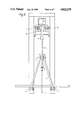
- FIG. 3 is a view of the apparatus according to FIG. 1 in an approximately vertical position with the drilling device in its upper position
- FIG. 4 is a diagrammatic view of the means holding and manipulating pipes in more detail
- FIG. 5 is a diagrammatic view of the means according to FIG. 4 as seen from the derrick,
- FIG. 6 is a diagrammatic view of the adjustable connection between the strongback and the brace unit
- FIG. 7 is a plan view of the connection in FIG. 6,
- FIG. 8 is a diagrammatic front view of the pipe handling apparatus, as seen towards the derrick, and
- FIG. 9 is a perspective view of the pipe handling apparatus according to the invention.
- FIG. 1 illustrates the pipe handling apparatus 35, a derrick 20, and a raising/lowering table 25.
- the drilling device 22 is of the top mounted type, i.e. the drilling device 22 driving the drill string 27 advances with the drill string 27 as the drill bit progresses downwardly in the borehole.
- the derrick 20 with associated drilling device 22 may be of the conventional kind with draw works hoisting means comprising a crown block, a travelling block and wireline arrangements. Other concepts for raising and lowering the drilling means, e.g. hydraulic cylinders, racks and screws may be adapted to the present system for manipulating pipes.
- a guide carriage 28 with a cross beam 21 guides and supports the drilling device 22 in derrick 20.
- Drilling device 22 is rotatable about a first axis 1 for approximately 90° permitting the drilling device 22 to occupy a substantially horizontal position.
- the raising/lowering table 25 supplies lying pipes 10 from a drill pipe storage or drill floor 40 up to a predetermined level.
- Table 25 comprises an endless belt 31 with cradles 26 of a rubber material or the like mounted on belt 31; said cradles 26 have recessed grooves for the pipe stands.
- the endless belt 31 may be driven either direction in order to roughly position pipe 10 in its horizontal position, by means of a motor (not shown).
- a motor, levers or hydraulic cylinders (not shown) move table 25 from drill floor 40 to a raised position.
- the pipe handling apparatus 35 comprises a strongback 4 which is rotatably attached to the drilling device 22.
- the drilling device 22 and strongback 4 are independently rotatable about the same first axis 1.
- Two or more arms 6 are slidably arranged on the strongback 4, which arms are provided with clamps 7 to grip a drill pipe 10 or a drill pipe stand.
- the clamps 7 comprise the means (not shown) for actuating said clamps to embrace a pipe, or vice versa, to open the clamps in order to release a pipe.
- a manipulator rod 8 is linked to the arms 6 in such a way that they enable synchronized operation. The manipulator rod 8 provides the final guidance of drill pipe 10 towards and into the drilling device 22.
- a brace unit 5 is rotatably attached to the strongback 4 about a second axis 2.
- the brace unit 5 is attached at one end to be rotatable about a third axis 3. Rotational movements preferably occur via journals and bearings.
- a slot or a coulisse guide 13 in a mounting bracket 32 restricts the movement of axis 3.
- a spring 29 is provided, primarily to hold axis 3 in its lower position in slot 13.
- Brace unit 5 may consist of two inclined legs, as will appear from FIGS. 8 and 9.
- FIG. 2 illustrates the apparatus 35 in a raised position.
- the raising/lowering table 25 is returned to drill floor 40.
- FIG. 3 illustrates the apparatus 35 in its fully raised position with strongback 4 in a substantially vertical position.
- the slot 13 provides safety during raising operations of the drilling device 22 and apparatus 35. If the drilling device 22 is moved slightly too high the axis 3 will be pulled upwardly along the slot 13 at the same time as spring 29 attempts to pull the brace unit 5 down.
- FIG. 4 illustrates an arm 6 with clamps 7 in more detail.
- FIG. 5 illustrates the same arrangement as FIG. 4, as seen from the derrick 20.
- the arm 6 is articulated by means of the link or pivot 19.
- the arm 6 is slidable on the strongback 4 by means of sliding and guiding faces 12.
- Manipulator rod 8 is linked to the arms 6 by means of a pin 33.
- a lug or pawl 11 is provided on the arms 6.
- the articulated arm 6 and lug 11 cooperating with the manipulator rod 8 permits the arm 6 to turn about the pivot 19 away from the derrick, and conversely towards the derrick until a position of said arm is orthogonal to the strongback 4.
- the lug 11 will cooperate with manipulator rod 8 to prevent further rotation.
- a further pull in the manipulator rod 8 will cause sliding displacement of the arm 6 along the strongback 4 and, thus, linear advancement of a drill pipe.
- FIG. 6 illustrates the rotatable connection 15 between the strongback 4 and the brace unit 5. These members turn relative to each other about the second axis 2.
- the strongback 4 and brace unit 5 are provided with means, e.g. in the form of racks 18, which may be displaced relative to each other.
- One or a plurality of motors may drive pinions 17 so as to adjust the strongback 4 and brace unit 5 to adapt the apparatus to pipe sections of different lengths.
- FIG. 7 illustrates the connection 15 of FIG. 6 in a plan view.
- a motor 16 is indicated for mutual displacement between the brace unit 5 and the strongback 4.
- a drill pipe 10 or a drill pipe stand consisting of two or three single pipes is moved from the drill pipe storage or drill floor 40 to a raised level by means of the raising/lowering table 25.
- the drilling device 22 When the drilling device 22 is in or approaches its lower position it is able to be turned about axis 1 to a lying or substantially horizontal position.
- the pipe 10 is roughly positioned relative to the drilling device 22 by means of the endless belt 31 providing only a slight distance between the drive shaft 34 of the drilling device 22 and the drill pipe 10.
- the clamps 7 embrace the pipe 10 and keep it fixed.
- the table 25 may then again be lowered towards the drill floor 40.
- the arms 6 are depending substantially vertically or orthogonally relative to the strongback 4 and, thus, the lug 11 cooperates with the manipulator rod 8.
- the drill pipe 10 is pulled towards the drive shaft 34 in the horizontal direction by means of sliding means 12 along the strongback 14.
- the mutual spaces and structural design will cause the central axis of the pipe 10 to coincide with the central axis of drive shaft 34 when the drill pipe is suspended in the clamps 7.
- the pipe 10 is advanced close to the shaft 34 said shaft is spun into the threaded end portion of the drill pipe 10.
- the drilling device 22 is elevated in the derrick 20 and pulls the strongback 4, thus raising the entire pipe handling apparatus 35. Successively the drill pipe 10 adapts a more vertical position.
- the drilling device 22 gradually turns about the first axis 1 while rising in the derrick 20.
- the brace unit 5 turns about the third axis 3. Due to said structural conditions the drill pipe is transferred directly to the drill centre 14 when the strongback 4 has occupied a substantially vertical position.
- the clamps 7 and the manipulator rod 8 are released, the outer portion of each articulated arm 6 falls due to its own weight.
- the arms 6 knuckle about the pivots 19.
- a roughneck 30 encircles the lower portion of the pipe, whereupon the drilling device and the pipe are lowered towards and into the upper threaded portion of the drill string 27.
- the pipe is spun into the threaded connection and makes up a predetermined momentum from the roughneck 30. The latter is subsequently removed and drilling may proceede.
- the pipe handling apparatus is designed to prevent axes 1,2 and 3 from being aligned when the drilling device 22 is in its upper position, but axis 2 is slightly offset from an imagined connecting line between axis 1 and 3. Thus, a knee is formed between the strongback 4 and brace unit 5 when the drilling device 22 is again lowered.
- a new drill pipe is placed on the raising/lowering table 25 and is transferred from the drill floor to the horizontal initial position of the pipe handling apparatus.
- the apparatus works in the opposite sequence. It should further be appreciated that the apparatus naturally can be used for round trip operations as well.
Abstract
A pipe handling apparatus is disclosed, which is adapted for automated drilling operations. Drill pipes are manipulated between substantially horizontal and vertical positions, and the apparatus is used with a top mounted drilling device which is rotatable about a substantially horizontal axis. The apparatus comprises a strongback provided with clamps to hold and manipulate pipes. The strongback is at one end portion rotatably connected to the same axis as the drilling device. The strongback moves up or down with the drilling device. A brace unit is attached to the strongback to be rotatable about a second axis spaced apart from said first axis. The brace unit has one end portion rotatable about a third axis.
Description
The present invention relates to a pipe handling apparatus adapted to automatic drilling operations, in which drill pipes are manipulated between substantially horizontal initial or final positions, and approximately vertical drill centre positions, for use with a top mounted drilling device which is rotatable about a substantially horizontal first axis.
Automatic systems for drilling operations are previously known which furthermore are able to carry out tripping operations, e.g. when a drill bit is to be replaced or logging or service operations are to be carried out. It is known that to pull out a drill string from oil or gas wells in the conventional way are very time consuming operations. Tripping operations are especially time consuming in case of drilling at greater depths requiring more frequent replacements of drill bits. The total drilling time in case of deep wells is, thus, considerably increased and results in increased costs.
U.S. Pat. No. 3,404,741 discloses an automated system for drilling and pipe manipulation. Drill pipes are placed in a horizontal position halfway up in the derrick before the pipes are manipulated into a vertical position. The structure comprises a drilling device which is rotatable about a horizontal axis. In its horizontal or lying position the pipe may be inserted into the drilling device which is subsequently raised permitting the pipe to be moved into a vertical position. At its other end the pipe is guided by a carriage moving on rails. During the raising operation the pipes are only supported at their end portions and, obviously, only short pipe lengths can be raised in this way. In order to reduce the time consumption it is, however, common and desirable today to manipulate pipe sections or stands comprising two or three assembled single pipes, i.e. sections that may be up to 30 m long.
U.S. Pat. No. 3,986,619 also describes equipment for manipulating pipes in order to move drill pipes from a horizontal into a vertical position. Entire pipe stands are manipulated by this system. The equipment comprises a mechanism elevating the stands in a horizontal position from the drill floor up to a predetermined level. The equipment for manipulating pipes comprises a series of blocks, pulleys and wires and is, apparently not adapted for automated operation.
With the equipment according to the invention the pipe handling operation may be automated thus avoiding time consuming and hazardous manual labour. Thus, time consumption, and consequently the total drilling costs may be reduced simultaneously as the work environmental conditions are considerably improved.
This is achieved by a pipe handling apparatus which is characterized by a strongback comprising means for holding and manipulating pipes, said strongback being connected at one end portion independently rotatable about said first axis for movement up or down with the drilling device, a brace unit rotatably connected to said strongback about a second axis spaced apart from said first axis, mounting means about which the end portion of said brace unit is rotatable about a third axis, said axis being arranged in such positions relative to each other that a drill pipe is moved from said horizontal position to the drilling centre in said substantially vertical position, or vice versa.
The means for holding pipes may comprise several spaced apart arms including pipe gripping means or clamps and means for operating said clamps to grip around the pipe. The means for holding and manipulating pipes may comprise means for synchronizing operation of the arms for inserting or retracting drill pipes relative to the drilling device. Said arms may be arranged to be slidable along the strongback, and they may be articulated and provided with arresting means preventing the arms from turning towards the drilling means more than into an approximately orthogonal position relative to the strongback when the arms are manipulated. The space between the first and second axes, and the space between the second and third axes is, suitably, adjustable, e.g. by means of a rack/pinion which is driven by a motor or the like.
Preferably, the third axis is restricted movably in a substantially vertical way in a slot or a coulisse guide, in order to provide a safety margin for the drilling device and the pipe handling apparatus when the drilling device approaches its upper position.
In order to ensure that the pipe stand may readily be removed from the drilling centre, the space between the longitudinal axis of the strongback and the longitudinal axis of the pipe stand in a manipulating position is advantageously longer than the horizontal space between the third axis and the drilling centre, so that a knuckling point is formed in the second axis.
Other and further objects, features, and advantages of the invention will appear from the following disclosure of an embodiment which is preferred at present and is meant for illustration together with the accompanied drawings.
FIG. 1 is a diagrammatic representation of the pipe handling apparatus according to the invention in a vertical section and in a folded or horizontal position together with a drilling device in a derrick,
FIG. 2 is a diagrammatic view of the apparatus according to FIG. 1, in a partially raised position,
FIG. 3 is a view of the apparatus according to FIG. 1 in an approximately vertical position with the drilling device in its upper position,
FIG. 4 is a diagrammatic view of the means holding and manipulating pipes in more detail,
FIG. 5 is a diagrammatic view of the means according to FIG. 4 as seen from the derrick,
FIG. 6 is a diagrammatic view of the adjustable connection between the strongback and the brace unit,
FIG. 7 is a plan view of the connection in FIG. 6,
FIG. 8 is a diagrammatic front view of the pipe handling apparatus, as seen towards the derrick, and
FIG. 9 is a perspective view of the pipe handling apparatus according to the invention.
An embodiment of the invention is shown in the drawings, in which FIG. 1 illustrates the pipe handling apparatus 35, a derrick 20, and a raising/lowering table 25. The drilling device 22 is of the top mounted type, i.e. the drilling device 22 driving the drill string 27 advances with the drill string 27 as the drill bit progresses downwardly in the borehole. The derrick 20 with associated drilling device 22 may be of the conventional kind with draw works hoisting means comprising a crown block, a travelling block and wireline arrangements. Other concepts for raising and lowering the drilling means, e.g. hydraulic cylinders, racks and screws may be adapted to the present system for manipulating pipes. A guide carriage 28 with a cross beam 21 guides and supports the drilling device 22 in derrick 20. Drilling device 22 is rotatable about a first axis 1 for approximately 90° permitting the drilling device 22 to occupy a substantially horizontal position.
The raising/lowering table 25 supplies lying pipes 10 from a drill pipe storage or drill floor 40 up to a predetermined level. Table 25 comprises an endless belt 31 with cradles 26 of a rubber material or the like mounted on belt 31; said cradles 26 have recessed grooves for the pipe stands. The endless belt 31 may be driven either direction in order to roughly position pipe 10 in its horizontal position, by means of a motor (not shown). A motor, levers or hydraulic cylinders (not shown) move table 25 from drill floor 40 to a raised position.
The pipe handling apparatus 35 comprises a strongback 4 which is rotatably attached to the drilling device 22. The drilling device 22 and strongback 4 are independently rotatable about the same first axis 1. Two or more arms 6 are slidably arranged on the strongback 4, which arms are provided with clamps 7 to grip a drill pipe 10 or a drill pipe stand. The clamps 7 comprise the means (not shown) for actuating said clamps to embrace a pipe, or vice versa, to open the clamps in order to release a pipe. A manipulator rod 8 is linked to the arms 6 in such a way that they enable synchronized operation. The manipulator rod 8 provides the final guidance of drill pipe 10 towards and into the drilling device 22. A brace unit 5 is rotatably attached to the strongback 4 about a second axis 2. The brace unit 5 is attached at one end to be rotatable about a third axis 3. Rotational movements preferably occur via journals and bearings. A slot or a coulisse guide 13 in a mounting bracket 32 restricts the movement of axis 3. In the lower portion of brace unit 5 a spring 29 is provided, primarily to hold axis 3 in its lower position in slot 13. Brace unit 5 may consist of two inclined legs, as will appear from FIGS. 8 and 9.
FIG. 2 illustrates the apparatus 35 in a raised position. The raising/lowering table 25 is returned to drill floor 40.
FIG. 3 illustrates the apparatus 35 in its fully raised position with strongback 4 in a substantially vertical position. The slot 13 provides safety during raising operations of the drilling device 22 and apparatus 35. If the drilling device 22 is moved slightly too high the axis 3 will be pulled upwardly along the slot 13 at the same time as spring 29 attempts to pull the brace unit 5 down.
FIG. 4 illustrates an arm 6 with clamps 7 in more detail. FIG. 5 illustrates the same arrangement as FIG. 4, as seen from the derrick 20. The arm 6 is articulated by means of the link or pivot 19. The arm 6 is slidable on the strongback 4 by means of sliding and guiding faces 12. Manipulator rod 8 is linked to the arms 6 by means of a pin 33. A lug or pawl 11 is provided on the arms 6. The articulated arm 6 and lug 11 cooperating with the manipulator rod 8 permits the arm 6 to turn about the pivot 19 away from the derrick, and conversely towards the derrick until a position of said arm is orthogonal to the strongback 4. By further movement of the arm 6 towards the derrick the lug 11 will cooperate with manipulator rod 8 to prevent further rotation. When the arm 6 is in an orthogonal position relative to the strongback 4, a further pull in the manipulator rod 8 will cause sliding displacement of the arm 6 along the strongback 4 and, thus, linear advancement of a drill pipe.
FIG. 6 illustrates the rotatable connection 15 between the strongback 4 and the brace unit 5. These members turn relative to each other about the second axis 2. The strongback 4 and brace unit 5 are provided with means, e.g. in the form of racks 18, which may be displaced relative to each other. One or a plurality of motors may drive pinions 17 so as to adjust the strongback 4 and brace unit 5 to adapt the apparatus to pipe sections of different lengths.
FIG. 7 illustrates the connection 15 of FIG. 6 in a plan view. A motor 16 is indicated for mutual displacement between the brace unit 5 and the strongback 4.
For a more detailed description of the pipe handling operation, reference is given to FIGS. 1-3. A drill pipe 10 or a drill pipe stand consisting of two or three single pipes is moved from the drill pipe storage or drill floor 40 to a raised level by means of the raising/lowering table 25. When the drilling device 22 is in or approaches its lower position it is able to be turned about axis 1 to a lying or substantially horizontal position. The pipe 10 is roughly positioned relative to the drilling device 22 by means of the endless belt 31 providing only a slight distance between the drive shaft 34 of the drilling device 22 and the drill pipe 10. The clamps 7 embrace the pipe 10 and keep it fixed. The table 25 may then again be lowered towards the drill floor 40. The arms 6 are depending substantially vertically or orthogonally relative to the strongback 4 and, thus, the lug 11 cooperates with the manipulator rod 8. When the rod 8 is pulled towards the drilling device 22 the drill pipe 10 is pulled towards the drive shaft 34 in the horizontal direction by means of sliding means 12 along the strongback 14. The mutual spaces and structural design will cause the central axis of the pipe 10 to coincide with the central axis of drive shaft 34 when the drill pipe is suspended in the clamps 7. When the pipe 10 is advanced close to the shaft 34 said shaft is spun into the threaded end portion of the drill pipe 10. In order to adapt a vertical position of the drill pipe 10 the drilling device 22 is elevated in the derrick 20 and pulls the strongback 4, thus raising the entire pipe handling apparatus 35. Successively the drill pipe 10 adapts a more vertical position. The drilling device 22 gradually turns about the first axis 1 while rising in the derrick 20. The brace unit 5 turns about the third axis 3. Due to said structural conditions the drill pipe is transferred directly to the drill centre 14 when the strongback 4 has occupied a substantially vertical position. When the clamps 7 and the manipulator rod 8 are released, the outer portion of each articulated arm 6 falls due to its own weight. The arms 6 knuckle about the pivots 19. A roughneck 30 encircles the lower portion of the pipe, whereupon the drilling device and the pipe are lowered towards and into the upper threaded portion of the drill string 27. The pipe is spun into the threaded connection and makes up a predetermined momentum from the roughneck 30. The latter is subsequently removed and drilling may procede. The pipe handling apparatus is designed to prevent axes 1,2 and 3 from being aligned when the drilling device 22 is in its upper position, but axis 2 is slightly offset from an imagined connecting line between axis 1 and 3. Thus, a knee is formed between the strongback 4 and brace unit 5 when the drilling device 22 is again lowered. During the rising and lowering operation a new drill pipe is placed on the raising/lowering table 25 and is transferred from the drill floor to the horizontal initial position of the pipe handling apparatus. When a drill string is retrieved the apparatus works in the opposite sequence. It should further be appreciated that the apparatus naturally can be used for round trip operations as well.
Claims (6)
1. A pipe-handling apparatus adapted for automatic drilling operations in which a plurality of drill pipes is manipulated in succession between a substantially horizontal initial or final position, and an approximately vertical drill center position, respectively, as a drill string is made-up and broken-down,
said pipe handling device comprising:
an upright, fixed derrick;
a top-mounted drilling device;
means mounting said drilling device to said derrick for moving up and down, and for rotating said drilling device through a right angle about a first, horizontal axis between a first orientation in which said drilling device projects vertically downwards, for turning a drill pipe, stand or drilling string, and a second orientation in which said drilling device projects horizontally away from the derrick for connecting with or disconnecting from a drill pipe or stand;
a pipe-supporting strongback comprising means for releasably holding a drill pipe or a stand of drill pipes, said strongback having one end rotatably connected with said drilling device for pivotal movement about said first axis as said drilling device moves up and down relative to said derrick;
a brace unit having a lower end and an upper end;
means pivotally mounting said brace unit to said strongback above said lower end of said brace unit, for angular movement about a second, horizontal axis which is parallel to but transversally displaced from said first axis;
means pivotally supporting said lower end of said brace unit, for angular movement about a third, horizontal axis which is parallel to but transversally displaced from said first and second axes, whereby
as said drilling device is raised and lowered, said strongback is angularly moved about said first and second axes and said brace unit is angularly moved about said second and third axes and consequently a drill pipe or stand, when held by said releasable holding means, is moved between said initial and final substantially horizontal positions, and said approximately vertical drill center position;
said releasable holding means comprising at least two arms mounted to said strongback at respective sites spaced longitudinally therealong, each arm having an openable, closable clamp mounted thereto for releasably holding a drill pipe or stand at respective sites spaced longitudinally along the drill pipe or stand, and means for operating said clamps to open and close them about said drill pipe or stand.
2. The pipe-handling apparatus of claim 1, further including:
means for synchronously moving said arms longitudinally of said strongback for inserting an end of a drill pipe into and retracting an end of a drill pipe from engagement with said drill device when a drill pipe or stand is releasably held by said clamps.
3. The pipe-handling apparatus of claim 2, wherein:
each said arm is articulated by a respective pivot joint to said strongback for angular movement about a respective horizontal axis; and
each said arm further includes stop means for preventing rotation of said arms toward said drilling device about said pivot joints when said clamps are holding a drill pipe or stand, beyond approximately orthogonal positions of said arms relative to said strongback as said arms are moved longitudinally of said strongback.
4. The pipe-handling apparatus of claim 1, wherein:
said means pivotally mounting said brace unit to said strongback is arranged for displacement longitudinally along said strongback and said brace unit for adjusting spacing between said second axis and said third axis; and
motor means operatively connected with said means pivotally mounting said brace unit to said strongback, for adjustably displacing said means pivotally mounting said brace unit to said strongback longitudinally along said strongback and said brace unit.
5. The pipe-handling apparatus of claim 1, wherein:
said means pivotally supporting said lower end of said brace unit, for angular movement about a third, horizontal axis is arranged to permit limited substantially vertical translation of said third axis.
6. The pipe-handling apparatus of claim 1, wherein:
when said drilling device is in said second orientation and lowered for connecting with or disconnecting from an end of a drill pipe or stand held by said clamps, said third axis and said drill center position are spaced apart horizontally by a distance which is less than the distance orthogonally between such drill pipe or stand and the longitudinal axis of said strongback.
Applications Claiming Priority (2)
| Application Number | Priority Date | Filing Date | Title |
|---|---|---|---|
| NO864219A NO161872C (en) | 1986-10-22 | 1986-10-22 | ROERHAANDTERINGSUTSTYR. |
| NO864219 | 1986-10-22 |
Publications (1)
| Publication Number | Publication Date |
|---|---|
| US4822230A true US4822230A (en) | 1989-04-18 |
Family
ID=19889318
Family Applications (1)
| Application Number | Title | Priority Date | Filing Date |
|---|---|---|---|
| US07/110,432 Expired - Fee Related US4822230A (en) | 1986-10-22 | 1987-10-20 | Pipe handling apparatus |
Country Status (10)
| Country | Link |
|---|---|
| US (1) | US4822230A (en) |
| EP (1) | EP0265234B1 (en) |
| BR (1) | BR8705840A (en) |
| CA (1) | CA1279883C (en) |
| DE (1) | DE3784442T2 (en) |
| DK (1) | DK552487A (en) |
| ES (1) | ES2039456T3 (en) |
| FI (1) | FI874632A (en) |
| NO (1) | NO161872C (en) |
| PT (1) | PT85969B (en) |
Cited By (53)
| Publication number | Priority date | Publication date | Assignee | Title |
|---|---|---|---|---|
| US5127790A (en) * | 1991-01-22 | 1992-07-07 | Teague J T | Pipe and casing handling method |
| US5458454A (en) * | 1992-04-30 | 1995-10-17 | The Dreco Group Of Companies Ltd. | Tubular handling method |
| US6085852A (en) * | 1995-02-22 | 2000-07-11 | The Charles Machine Works, Inc. | Pipe handling device |
| US6179065B1 (en) | 1998-09-02 | 2001-01-30 | The Charles Machine Works, Inc. | System and method for automatically controlling a pipe handling system for a horizontal boring machine |
| EP1103695A2 (en) * | 1999-11-26 | 2001-05-30 | Compagnie Du Sol | Device for mounting a drilling tool on a mast |
| US6524030B1 (en) | 1998-07-22 | 2003-02-25 | Saipem S.P.A. | Underwater pipe-laying |
| US6705414B2 (en) | 2002-02-22 | 2004-03-16 | Globalsantafe Corporation | Tubular transfer system |
| US20040131449A1 (en) * | 2002-10-04 | 2004-07-08 | Thompson Carroll R. | Pipe handling apparatus for pick-up and lay-down machine |
| US20040131425A1 (en) * | 2001-03-27 | 2004-07-08 | Luciano Tosi | Underwater pipe-laying |
| US20040136813A1 (en) * | 1998-02-14 | 2004-07-15 | Weatherford/Lamb, Inc. | Apparatus for delivering a tubular to a wellbore |
| US20050173154A1 (en) * | 2004-01-28 | 2005-08-11 | Gerald Lesko | Method and system for connecting pipe to a top drive motor |
| US7013977B2 (en) | 2003-06-11 | 2006-03-21 | Halliburton Energy Services, Inc. | Sealed connectors for automatic gun handling |
| WO2006038790A1 (en) * | 2004-10-07 | 2006-04-13 | Itrec B.V. | Tubular handling apparatus and a drilling rig |
| WO2006075914A1 (en) * | 2005-01-12 | 2006-07-20 | Morten Eriksen | A device for handling of pipes at a drill floor |
| US20060243488A1 (en) * | 2005-05-02 | 2006-11-02 | Weatherford/Lamb, Inc. | Tailing in and stabbing device |
| US7189028B1 (en) | 1999-07-21 | 2007-03-13 | Saipem, S.P.A. | Underwater pipe-laying |
| US20080060850A1 (en) * | 2006-09-11 | 2008-03-13 | Collier Equipment Fabrication Company | System and methods for handling drilling pipe |
| US20080202812A1 (en) * | 2007-02-23 | 2008-08-28 | Atwood Oceanics, Inc. | Simultaneous tubular handling system |
| US20080304938A1 (en) * | 2007-06-08 | 2008-12-11 | Brian Michael Katterhenry | Strongback Traveling Clamp |
| US20090232624A1 (en) * | 2007-10-24 | 2009-09-17 | T&T Engineering Services | Pipe handling apparatus with arm stiffening |
| US20100032213A1 (en) * | 2007-10-24 | 2010-02-11 | T&T Engineering Services | Apparatus and method for pre-loading of a main rotating structural member |
| US20100104401A1 (en) * | 2008-10-27 | 2010-04-29 | Hopkins James R | Automated rod handling system |
| US7726929B1 (en) | 2007-10-24 | 2010-06-01 | T&T Engineering Services | Pipe handling boom pretensioning apparatus |
| US20100230166A1 (en) * | 2009-03-12 | 2010-09-16 | T&T Engineering Services | Derrickless tubular servicing system and method |
| US20100254784A1 (en) * | 2009-04-03 | 2010-10-07 | T & T Engineering Services | Raise-assist and smart energy system for a pipe handling apparatus |
| US20100296899A1 (en) * | 2009-05-20 | 2010-11-25 | T&T Engineering Services | Alignment apparatus and method for a boom of a pipe handling system |
| US20110030942A1 (en) * | 2009-08-04 | 2011-02-10 | T&T Engineering Services, Inc. | Pipe stand |
| US7918636B1 (en) * | 2007-10-24 | 2011-04-05 | T&T Engineering Services | Pipe handling apparatus and method |
| US20110091304A1 (en) * | 2009-10-16 | 2011-04-21 | Friede & Goldman Marketing B.V. | Cartridge tubular handling system |
| US7946795B2 (en) | 2007-10-24 | 2011-05-24 | T & T Engineering Services, Inc. | Telescoping jack for a gripper assembly |
| US8128332B2 (en) | 2007-10-24 | 2012-03-06 | T & T Engineering Services, Inc. | Header structure for a pipe handling apparatus |
| US20120097454A1 (en) * | 2009-05-07 | 2012-04-26 | Rupert Kockeis | Apparatus and Method of Handling Rod-Shaped Components |
| US20120195716A1 (en) * | 2009-08-05 | 2012-08-02 | Itrec B.V. | Tubular handling system and method for handling tubulars |
| US8235104B1 (en) | 2008-12-17 | 2012-08-07 | T&T Engineering Services, Inc. | Apparatus for pipe tong and spinner deployment |
| US8408334B1 (en) | 2008-12-11 | 2013-04-02 | T&T Engineering Services, Inc. | Stabbing apparatus and method |
| US8419335B1 (en) | 2007-10-24 | 2013-04-16 | T&T Engineering Services, Inc. | Pipe handling apparatus with stab frame stiffening |
| CN103299023A (en) * | 2010-12-30 | 2013-09-11 | 阿特拉斯科普柯克雷柳斯有限公司 | Device and method for handling drill string components, as well as rock drilling rig |
| US8550174B1 (en) | 2008-12-22 | 2013-10-08 | T&T Engineering Services, Inc. | Stabbing apparatus for centering tubulars and casings for connection at a wellhead |
| US8876452B2 (en) | 2009-04-03 | 2014-11-04 | T&T Engineering Services, Inc. | Raise-assist and smart energy system for a pipe handling apparatus |
| WO2014179741A1 (en) * | 2013-05-03 | 2014-11-06 | Canrig Drilling Technology Ltd. | System and method for manipulating tubulars for subterranean operations |
| US9027287B2 (en) | 2010-12-30 | 2015-05-12 | T&T Engineering Services, Inc. | Fast transportable drilling rig system |
| US20150144402A1 (en) * | 2012-06-28 | 2015-05-28 | Atlas Copco Craelius Ab | Handling device and method for handling drill string components in rock drilling and rock drill rig |
| US9091128B1 (en) | 2011-11-18 | 2015-07-28 | T&T Engineering Services, Inc. | Drill floor mountable automated pipe racking system |
| US9441427B2 (en) | 2012-10-22 | 2016-09-13 | Ensco Services Limited | Automated pipe tripping apparatus and methods |
| US9476267B2 (en) | 2013-03-15 | 2016-10-25 | T&T Engineering Services, Inc. | System and method for raising and lowering a drill floor mountable automated pipe racking system |
| US20160319614A1 (en) * | 2015-04-28 | 2016-11-03 | 1311854 Ontario Limited | Elastomeric centralizer base for rock drilling system |
| US9500049B1 (en) | 2008-12-11 | 2016-11-22 | Schlumberger Technology Corporation | Grip and vertical stab apparatus and method |
| US9556689B2 (en) | 2009-05-20 | 2017-01-31 | Schlumberger Technology Corporation | Alignment apparatus and method for a boom of a pipe handling system |
| CN106461121A (en) * | 2014-04-14 | 2017-02-22 | 伊特里克公司 | Pipe installation system for J-pipe laying, offshore pipelaying system and method of treating a pipe or fitting |
| US9863194B2 (en) | 2013-05-03 | 2018-01-09 | Canrig Drilling Technology Ltd. | System for manipulating tubulars for subterranean operations |
| US10294737B2 (en) | 2017-03-23 | 2019-05-21 | Ensco International Incorporated | Vertical lift rotary table |
| US20220003055A1 (en) * | 2020-07-06 | 2022-01-06 | Canrig Robotic Technologies As | Robotic pipe handler systems |
| US11767719B2 (en) | 2020-09-01 | 2023-09-26 | Canrig Robotic Technologies As | Robotic pipe handler |
Families Citing this family (1)
| Publication number | Priority date | Publication date | Assignee | Title |
|---|---|---|---|---|
| US5720354A (en) | 1996-01-11 | 1998-02-24 | Vermeer Manufacturing Company | Trenchless underground boring system with boring tool location |
Citations (3)
| Publication number | Priority date | Publication date | Assignee | Title |
|---|---|---|---|---|
| US2956782A (en) * | 1955-10-28 | 1960-10-18 | Darrel D Mistrot | Well drilling machine |
| US3404741A (en) * | 1962-12-28 | 1968-10-08 | Ministerul Ind Petrolui Si Chi | Automated system and drilling rig for continuously and automatically pulling and running a drill-pipe string |
| US3633771A (en) * | 1970-08-05 | 1972-01-11 | Moore Corp Lee C | Apparatus for moving drill pipe into and out of an oil well derrick |
Family Cites Families (2)
| Publication number | Priority date | Publication date | Assignee | Title |
|---|---|---|---|---|
| US3795326A (en) * | 1972-05-22 | 1974-03-05 | Armco Steel Corp | Apparatus for handling drill pipe |
| US3986619A (en) * | 1975-06-11 | 1976-10-19 | Lee C. Moore Corporation | Pipe handling apparatus for oil well drilling derrick |
-
1986
- 1986-10-22 NO NO864219A patent/NO161872C/en unknown
-
1987
- 1987-10-20 US US07/110,432 patent/US4822230A/en not_active Expired - Fee Related
- 1987-10-21 PT PT85969A patent/PT85969B/en not_active IP Right Cessation
- 1987-10-21 EP EP87309280A patent/EP0265234B1/en not_active Expired - Lifetime
- 1987-10-21 CA CA000549863A patent/CA1279883C/en not_active Expired - Lifetime
- 1987-10-21 DE DE8787309280T patent/DE3784442T2/en not_active Expired - Fee Related
- 1987-10-21 FI FI874632A patent/FI874632A/en not_active Application Discontinuation
- 1987-10-21 ES ES198787309280T patent/ES2039456T3/en not_active Expired - Lifetime
- 1987-10-21 DK DK552487A patent/DK552487A/en not_active Application Discontinuation
- 1987-10-22 BR BR8705840A patent/BR8705840A/en unknown
Patent Citations (3)
| Publication number | Priority date | Publication date | Assignee | Title |
|---|---|---|---|---|
| US2956782A (en) * | 1955-10-28 | 1960-10-18 | Darrel D Mistrot | Well drilling machine |
| US3404741A (en) * | 1962-12-28 | 1968-10-08 | Ministerul Ind Petrolui Si Chi | Automated system and drilling rig for continuously and automatically pulling and running a drill-pipe string |
| US3633771A (en) * | 1970-08-05 | 1972-01-11 | Moore Corp Lee C | Apparatus for moving drill pipe into and out of an oil well derrick |
Cited By (109)
| Publication number | Priority date | Publication date | Assignee | Title |
|---|---|---|---|---|
| US5127790A (en) * | 1991-01-22 | 1992-07-07 | Teague J T | Pipe and casing handling method |
| US5458454A (en) * | 1992-04-30 | 1995-10-17 | The Dreco Group Of Companies Ltd. | Tubular handling method |
| US6220807B1 (en) | 1992-04-30 | 2001-04-24 | Dreco Energy Services Ltd. | Tubular handling system |
| US6543551B1 (en) | 1995-02-22 | 2003-04-08 | The Charles Machine Works, Inc. | Pipe handling device |
| US6085852A (en) * | 1995-02-22 | 2000-07-11 | The Charles Machine Works, Inc. | Pipe handling device |
| US8079796B2 (en) * | 1998-02-14 | 2011-12-20 | Weatherford/Lamb, Inc. | Apparatus for delivering a tubular to a wellbore |
| US20040136813A1 (en) * | 1998-02-14 | 2004-07-15 | Weatherford/Lamb, Inc. | Apparatus for delivering a tubular to a wellbore |
| US20030219313A1 (en) * | 1998-07-22 | 2003-11-27 | Umberto Giovannini | Underwater pipe-laying |
| US6524030B1 (en) | 1998-07-22 | 2003-02-25 | Saipem S.P.A. | Underwater pipe-laying |
| US6550547B1 (en) | 1998-09-02 | 2003-04-22 | The Charles Machine Works, Inc. | System and method for automatically controlling a pipe handling system for a horizontal boring machine |
| US6179065B1 (en) | 1998-09-02 | 2001-01-30 | The Charles Machine Works, Inc. | System and method for automatically controlling a pipe handling system for a horizontal boring machine |
| US7189028B1 (en) | 1999-07-21 | 2007-03-13 | Saipem, S.P.A. | Underwater pipe-laying |
| EP1103695A2 (en) * | 1999-11-26 | 2001-05-30 | Compagnie Du Sol | Device for mounting a drilling tool on a mast |
| EP1103695A3 (en) * | 1999-11-26 | 2003-01-15 | Compagnie Du Sol | Device for mounting a drilling tool on a mast |
| FR2801633A1 (en) * | 1999-11-26 | 2001-06-01 | Cie Du Sol | DEVICE FOR MOUNTING A DRILLING TOOL ON A MAT |
| US20040131425A1 (en) * | 2001-03-27 | 2004-07-08 | Luciano Tosi | Underwater pipe-laying |
| US6939083B2 (en) | 2001-03-27 | 2005-09-06 | Saipem S.P.A. | Apparatus and method for connecting pipes during underwater pipe-laying |
| US6705414B2 (en) | 2002-02-22 | 2004-03-16 | Globalsantafe Corporation | Tubular transfer system |
| US20040131449A1 (en) * | 2002-10-04 | 2004-07-08 | Thompson Carroll R. | Pipe handling apparatus for pick-up and lay-down machine |
| US7431550B2 (en) * | 2002-10-04 | 2008-10-07 | Technologies Alliance | Pipe handling apparatus for pick-up and lay-down machine |
| US7013977B2 (en) | 2003-06-11 | 2006-03-21 | Halliburton Energy Services, Inc. | Sealed connectors for automatic gun handling |
| US20050173154A1 (en) * | 2004-01-28 | 2005-08-11 | Gerald Lesko | Method and system for connecting pipe to a top drive motor |
| US7090035B2 (en) | 2004-01-28 | 2006-08-15 | Gerald Lesko | Method and system for connecting pipe to a top drive motor |
| US20080253866A1 (en) * | 2004-10-07 | 2008-10-16 | Itrec B.V. | Tubular Handling Apparatus and a Drilling Rig |
| US7744327B2 (en) * | 2004-10-07 | 2010-06-29 | Itrec B.V. | Tubular handling apparatus and a drilling rig |
| WO2006038790A1 (en) * | 2004-10-07 | 2006-04-13 | Itrec B.V. | Tubular handling apparatus and a drilling rig |
| GB2437663A (en) * | 2005-01-12 | 2007-10-31 | Morten Eriksen | A device for handling of pipes at a drill floor |
| US20080128167A1 (en) * | 2005-01-12 | 2008-06-05 | Morten Eriksen | Device for Handling of Pipes at a Drill Floor |
| GB2437663B (en) * | 2005-01-12 | 2008-09-10 | Morten Eriksen | A device for handling of pipes at a drill floor |
| US7699122B2 (en) | 2005-01-12 | 2010-04-20 | Morten Eriksen | Device for handling of pipes at a drill floor |
| WO2006075914A1 (en) * | 2005-01-12 | 2006-07-20 | Morten Eriksen | A device for handling of pipes at a drill floor |
| US7552775B2 (en) | 2005-05-02 | 2009-06-30 | Weatherford/Lamb, Inc. | Tailing in and stabbing device and method |
| US20060243488A1 (en) * | 2005-05-02 | 2006-11-02 | Weatherford/Lamb, Inc. | Tailing in and stabbing device |
| US20080060850A1 (en) * | 2006-09-11 | 2008-03-13 | Collier Equipment Fabrication Company | System and methods for handling drilling pipe |
| US10612323B2 (en) | 2007-02-23 | 2020-04-07 | Friede & Goldman United B.V. | Simultaneous tubular handling system |
| US9410385B2 (en) | 2007-02-23 | 2016-08-09 | Friede Goldman United, Ltd. | Simultaneous tubular handling system |
| US8584773B2 (en) | 2007-02-23 | 2013-11-19 | Atwood Oceanics, Inc. | Simultaneous tubular handling system and method |
| US20080202812A1 (en) * | 2007-02-23 | 2008-08-28 | Atwood Oceanics, Inc. | Simultaneous tubular handling system |
| US8186455B2 (en) | 2007-02-23 | 2012-05-29 | Atwood Oceanics, Inc. | Simultaneous tubular handling system and method |
| US7802636B2 (en) | 2007-02-23 | 2010-09-28 | Atwood Oceanics, Inc. | Simultaneous tubular handling system and method |
| US20080304938A1 (en) * | 2007-06-08 | 2008-12-11 | Brian Michael Katterhenry | Strongback Traveling Clamp |
| US8192129B1 (en) | 2007-10-24 | 2012-06-05 | T&T Engineering Services, Inc. | Pipe handling boom pretensioning apparatus |
| US8128332B2 (en) | 2007-10-24 | 2012-03-06 | T & T Engineering Services, Inc. | Header structure for a pipe handling apparatus |
| US20090232624A1 (en) * | 2007-10-24 | 2009-09-17 | T&T Engineering Services | Pipe handling apparatus with arm stiffening |
| US7918636B1 (en) * | 2007-10-24 | 2011-04-05 | T&T Engineering Services | Pipe handling apparatus and method |
| US8696288B2 (en) | 2007-10-24 | 2014-04-15 | T&T Engineering Services, Inc. | Pipe handling boom pretensioning apparatus |
| US7946795B2 (en) | 2007-10-24 | 2011-05-24 | T & T Engineering Services, Inc. | Telescoping jack for a gripper assembly |
| US7980802B2 (en) | 2007-10-24 | 2011-07-19 | T&T Engineering Services | Pipe handling apparatus with arm stiffening |
| US20110200412A1 (en) * | 2007-10-24 | 2011-08-18 | T&T Engineering Services | Pipe Handling Apparatus and Method |
| US8506229B2 (en) | 2007-10-24 | 2013-08-13 | T&T Engineering Services, Inc. | Pipe handling apparatus and method |
| US9194193B1 (en) | 2007-10-24 | 2015-11-24 | T&T Engineering Services, Inc. | Pipe handling apparatus and method |
| US8469648B2 (en) | 2007-10-24 | 2013-06-25 | T&T Engineering Services | Apparatus and method for pre-loading of a main rotating structural member |
| US8419335B1 (en) | 2007-10-24 | 2013-04-16 | T&T Engineering Services, Inc. | Pipe handling apparatus with stab frame stiffening |
| US20100032213A1 (en) * | 2007-10-24 | 2010-02-11 | T&T Engineering Services | Apparatus and method for pre-loading of a main rotating structural member |
| US8393844B2 (en) | 2007-10-24 | 2013-03-12 | T&T Engineering Services, Inc. | Header structure for a pipe handling apparatus |
| US7726929B1 (en) | 2007-10-24 | 2010-06-01 | T&T Engineering Services | Pipe handling boom pretensioning apparatus |
| US20100104401A1 (en) * | 2008-10-27 | 2010-04-29 | Hopkins James R | Automated rod handling system |
| US8240968B2 (en) | 2008-10-27 | 2012-08-14 | Laibe Corporation | Automated rod handling system |
| US8408334B1 (en) | 2008-12-11 | 2013-04-02 | T&T Engineering Services, Inc. | Stabbing apparatus and method |
| US9500049B1 (en) | 2008-12-11 | 2016-11-22 | Schlumberger Technology Corporation | Grip and vertical stab apparatus and method |
| US8235104B1 (en) | 2008-12-17 | 2012-08-07 | T&T Engineering Services, Inc. | Apparatus for pipe tong and spinner deployment |
| US8550174B1 (en) | 2008-12-22 | 2013-10-08 | T&T Engineering Services, Inc. | Stabbing apparatus for centering tubulars and casings for connection at a wellhead |
| US8371790B2 (en) | 2009-03-12 | 2013-02-12 | T&T Engineering Services, Inc. | Derrickless tubular servicing system and method |
| US20100230166A1 (en) * | 2009-03-12 | 2010-09-16 | T&T Engineering Services | Derrickless tubular servicing system and method |
| US8172497B2 (en) | 2009-04-03 | 2012-05-08 | T & T Engineering Services | Raise-assist and smart energy system for a pipe handling apparatus |
| US8876452B2 (en) | 2009-04-03 | 2014-11-04 | T&T Engineering Services, Inc. | Raise-assist and smart energy system for a pipe handling apparatus |
| US20100254784A1 (en) * | 2009-04-03 | 2010-10-07 | T & T Engineering Services | Raise-assist and smart energy system for a pipe handling apparatus |
| US9556688B2 (en) | 2009-04-03 | 2017-01-31 | Schlumberger Technology Corporation | Raise-assist and smart energy system for a pipe handling apparatus |
| US8910719B2 (en) * | 2009-05-07 | 2014-12-16 | Max Streicher Gmbh & Co. Kg Aa | Apparatus and method of handling rod-shaped components |
| US20120097454A1 (en) * | 2009-05-07 | 2012-04-26 | Rupert Kockeis | Apparatus and Method of Handling Rod-Shaped Components |
| US8905699B2 (en) | 2009-05-20 | 2014-12-09 | T&T Engineering Services, Inc. | Alignment apparatus and method for a boom of a pipe handling system |
| US8192128B2 (en) | 2009-05-20 | 2012-06-05 | T&T Engineering Services, Inc. | Alignment apparatus and method for a boom of a pipe handling system |
| US9556689B2 (en) | 2009-05-20 | 2017-01-31 | Schlumberger Technology Corporation | Alignment apparatus and method for a boom of a pipe handling system |
| US20100296899A1 (en) * | 2009-05-20 | 2010-11-25 | T&T Engineering Services | Alignment apparatus and method for a boom of a pipe handling system |
| US20110030942A1 (en) * | 2009-08-04 | 2011-02-10 | T&T Engineering Services, Inc. | Pipe stand |
| US8469085B2 (en) | 2009-08-04 | 2013-06-25 | T&T Engineering Services, Inc. | Pipe stand |
| US20120195716A1 (en) * | 2009-08-05 | 2012-08-02 | Itrec B.V. | Tubular handling system and method for handling tubulars |
| CN102686925A (en) * | 2009-08-05 | 2012-09-19 | 伊特雷科公司 | Tubular handling system and method for handling tubulars |
| CN102686925B (en) * | 2009-08-05 | 2015-11-25 | 伊特雷科公司 | Pipe fitting handling system and the method for carrying pipe fitting |
| US8992152B2 (en) * | 2009-08-05 | 2015-03-31 | Itrec B.V. | Tubular handling system and method for handling tubulars |
| US8215888B2 (en) | 2009-10-16 | 2012-07-10 | Friede Goldman United, Ltd. | Cartridge tubular handling system |
| US8696289B2 (en) | 2009-10-16 | 2014-04-15 | Friede Goldman United, Ltd. | Cartridge tubular handling system |
| US20110091304A1 (en) * | 2009-10-16 | 2011-04-21 | Friede & Goldman Marketing B.V. | Cartridge tubular handling system |
| US9476265B2 (en) | 2009-10-16 | 2016-10-25 | Friede Goldman United, Ltd. | Trolley apparatus |
| US9359784B2 (en) | 2010-12-30 | 2016-06-07 | T&T Engineering Services, Inc. | Fast transportable drilling rig system |
| US9428970B2 (en) | 2010-12-30 | 2016-08-30 | Atlas Copco Craelius Ab | Device and method for handling drill string components, as well as rock drilling rig |
| US9719271B2 (en) | 2010-12-30 | 2017-08-01 | Schlumberger Technology Corporation | Fast transportable drilling rig system |
| US10808415B2 (en) | 2010-12-30 | 2020-10-20 | Schlumberger Technology Corporation | Fast transportable drilling rig system |
| US9702161B2 (en) | 2010-12-30 | 2017-07-11 | Schlumberger Technology Corporation | Fast transportable drilling rig system |
| CN103299023A (en) * | 2010-12-30 | 2013-09-11 | 阿特拉斯科普柯克雷柳斯有限公司 | Device and method for handling drill string components, as well as rock drilling rig |
| US9027287B2 (en) | 2010-12-30 | 2015-05-12 | T&T Engineering Services, Inc. | Fast transportable drilling rig system |
| US9945193B1 (en) | 2011-11-18 | 2018-04-17 | Schlumberger Technology Corporation | Drill floor mountable automated pipe racking system |
| US9091128B1 (en) | 2011-11-18 | 2015-07-28 | T&T Engineering Services, Inc. | Drill floor mountable automated pipe racking system |
| US9790752B2 (en) * | 2012-06-28 | 2017-10-17 | Atlas Copco Craelius Ab | Handling device and method for handling drill string components in rock drilling and rock drill rig |
| US20150144402A1 (en) * | 2012-06-28 | 2015-05-28 | Atlas Copco Craelius Ab | Handling device and method for handling drill string components in rock drilling and rock drill rig |
| US10214977B2 (en) | 2012-10-22 | 2019-02-26 | Ensco Services Limited | Automated pipe tripping apparatus and methods |
| US10975639B2 (en) | 2012-10-22 | 2021-04-13 | Ensco Services Limited | Automated pipe tripping apparatus and methods |
| US9441427B2 (en) | 2012-10-22 | 2016-09-13 | Ensco Services Limited | Automated pipe tripping apparatus and methods |
| US9476267B2 (en) | 2013-03-15 | 2016-10-25 | T&T Engineering Services, Inc. | System and method for raising and lowering a drill floor mountable automated pipe racking system |
| WO2014179741A1 (en) * | 2013-05-03 | 2014-11-06 | Canrig Drilling Technology Ltd. | System and method for manipulating tubulars for subterranean operations |
| US9863194B2 (en) | 2013-05-03 | 2018-01-09 | Canrig Drilling Technology Ltd. | System for manipulating tubulars for subterranean operations |
| CN106461121A (en) * | 2014-04-14 | 2017-02-22 | 伊特里克公司 | Pipe installation system for J-pipe laying, offshore pipelaying system and method of treating a pipe or fitting |
| US10400526B2 (en) * | 2015-04-28 | 2019-09-03 | 1311854 Ontario Limited | Elastomeric centralizer base for rock drilling system |
| US20160319614A1 (en) * | 2015-04-28 | 2016-11-03 | 1311854 Ontario Limited | Elastomeric centralizer base for rock drilling system |
| US10294737B2 (en) | 2017-03-23 | 2019-05-21 | Ensco International Incorporated | Vertical lift rotary table |
| US10745980B2 (en) | 2017-03-23 | 2020-08-18 | Ensco International Incorporated | Vertical lift rotary table |
| US20220003055A1 (en) * | 2020-07-06 | 2022-01-06 | Canrig Robotic Technologies As | Robotic pipe handler systems |
| US11643887B2 (en) * | 2020-07-06 | 2023-05-09 | Canrig Robotic Technologies As | Robotic pipe handler systems |
| US11767719B2 (en) | 2020-09-01 | 2023-09-26 | Canrig Robotic Technologies As | Robotic pipe handler |
Also Published As
| Publication number | Publication date |
|---|---|
| FI874632A0 (en) | 1987-10-21 |
| CA1279883C (en) | 1991-02-05 |
| NO864219L (en) | 1988-04-25 |
| NO161872B (en) | 1989-06-26 |
| DK552487A (en) | 1988-04-23 |
| NO864219D0 (en) | 1986-10-22 |
| NO161872C (en) | 1989-10-04 |
| EP0265234A2 (en) | 1988-04-27 |
| EP0265234A3 (en) | 1989-03-08 |
| BR8705840A (en) | 1988-05-31 |
| ES2039456T3 (en) | 1993-10-01 |
| DE3784442T2 (en) | 1993-08-19 |
| DK552487D0 (en) | 1987-10-21 |
| EP0265234B1 (en) | 1993-03-03 |
| PT85969B (en) | 1993-08-31 |
| PT85969A (en) | 1988-11-30 |
| FI874632A (en) | 1988-04-23 |
| DE3784442D1 (en) | 1993-04-08 |
Similar Documents
| Publication | Publication Date | Title |
|---|---|---|
| US4822230A (en) | Pipe handling apparatus | |
| EP0285385B1 (en) | Top head drive assembly for earth drilling machine and components thereof | |
| EP1953334B1 (en) | A pipe handling system and method | |
| US7090035B2 (en) | Method and system for connecting pipe to a top drive motor | |
| CA1187867A (en) | Pipe handling apparatus with holding means for trough of pipe handling apparatus | |
| US4765401A (en) | Apparatus for handling well pipe | |
| US3655071A (en) | Horizontal pipe racking and handling apparatus | |
| US3883009A (en) | Racking arm for pipe sections, drill collars, riser pipe, and the like used in well drilling operations | |
| US8469085B2 (en) | Pipe stand | |
| US3561811A (en) | Well pipe racker | |
| US4077525A (en) | Derrick mounted apparatus for the manipulation of pipe | |
| US8961093B2 (en) | Drilling rig pipe transfer systems and methods | |
| US9500049B1 (en) | Grip and vertical stab apparatus and method | |
| US8550174B1 (en) | Stabbing apparatus for centering tubulars and casings for connection at a wellhead | |
| EP0267002A2 (en) | Automatic pipe racking apparatus | |
| US20070251700A1 (en) | Tubular running system | |
| CN107849903A (en) | Drilling rig having a top drive system operating in a drilling mode and a tripping mode | |
| CN85108188B (en) | Drilling and/or lifting machine | |
| US3650339A (en) | Slant hole drilling rig | |
| AU5417498A (en) | Handling of tube sections in a rig for subsoil drilling | |
| US8408334B1 (en) | Stabbing apparatus and method | |
| US3929235A (en) | System for handling and racking pipe in the hold of a vessel | |
| CN108533194A (en) | Land rig quadruple board platform automatic tube-arranging system | |
| US3633767A (en) | Pipe-racking apparatus for oil well derricks or the like | |
| US3805902A (en) | Well drilling apparatus and method |
Legal Events
| Date | Code | Title | Description |
|---|---|---|---|
| AS | Assignment |
Owner name: MARITIME HYDRAULICS A.S, DVERGSNES, N-4639 KRISTIA Free format text: ASSIGNMENT OF ASSIGNORS INTEREST.;ASSIGNOR:SLETTEDAL, PER;REEL/FRAME:004810/0709 Effective date: 19871005 |
|
| FEPP | Fee payment procedure |
Free format text: PAYOR NUMBER ASSIGNED (ORIGINAL EVENT CODE: ASPN); ENTITY STATUS OF PATENT OWNER: LARGE ENTITY |
|
| FPAY | Fee payment |
Year of fee payment: 4 |
|
| REMI | Maintenance fee reminder mailed | ||
| LAPS | Lapse for failure to pay maintenance fees | ||
| FP | Lapsed due to failure to pay maintenance fee |
Effective date: 19970423 |
|
| STCH | Information on status: patent discontinuation |
Free format text: PATENT EXPIRED DUE TO NONPAYMENT OF MAINTENANCE FEES UNDER 37 CFR 1.362 |