US482099A - Stone cutting and dressing machine - Google Patents
Stone cutting and dressing machine Download PDFInfo
- Publication number
- US482099A US482099A US482099DA US482099A US 482099 A US482099 A US 482099A US 482099D A US482099D A US 482099DA US 482099 A US482099 A US 482099A
- Authority
- US
- United States
- Prior art keywords
- tool
- frame
- stone
- bar
- tools
- Prior art date
- Legal status (The legal status is an assumption and is not a legal conclusion. Google has not performed a legal analysis and makes no representation as to the accuracy of the status listed.)
- Expired - Lifetime
Links
- 239000004575 stone Substances 0.000 title description 14
- 230000033001 locomotion Effects 0.000 description 7
- 238000010276 construction Methods 0.000 description 2
- 230000006378 damage Effects 0.000 description 2
- 239000010438 granite Substances 0.000 description 2
- 230000004048 modification Effects 0.000 description 2
- 238000012986 modification Methods 0.000 description 2
- 230000002441 reversible effect Effects 0.000 description 2
- 230000035939 shock Effects 0.000 description 2
- 208000027418 Wounds and injury Diseases 0.000 description 1
- 208000014674 injury Diseases 0.000 description 1
- 230000001105 regulatory effect Effects 0.000 description 1
- 238000007790 scraping Methods 0.000 description 1
Images
Classifications
-
- B—PERFORMING OPERATIONS; TRANSPORTING
- B28—WORKING CEMENT, CLAY, OR STONE
- B28D—WORKING STONE OR STONE-LIKE MATERIALS
- B28D1/00—Working stone or stone-like materials, e.g. brick, concrete or glass, not provided for elsewhere; Machines, devices, tools therefor
- B28D1/26—Working stone or stone-like materials, e.g. brick, concrete or glass, not provided for elsewhere; Machines, devices, tools therefor by impact tools, e.g. by chisels or other tools having a cutting edge
Definitions
- Tn 04mm: PETERS co UNITED STATES PATENT OFFICE.
- This invention relates to machines for cutting, dressing, and chiseling stone, and is in the general nature of an improvement upon the structure set forth in an application for Letters Patent of the United States filed by me April 7, 1891, Serial No. 387,968.
- the object of my present invention is to devise a structure more particularly adapted for use in operating upon stone of extreme hardness, such as granite; and to this end my invention consists in certain novel features, which I will now proceed to describe, and will then particularly point. out in the appended claims.
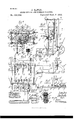
- FIG. 1 is a plan section, taken on the line 1 1 of Fig. 2 and looking in the direction of the arrows, of a machine embodying my invention, only so much thereof being shown as is necessary for a proper comprehension of the same.
- Fig. 2 is a vertical sectional view taken on the line 2 2 of Fig. 1 and looking in the direction of the arrows.
- Fig. 3 is a side elevation, partly in section, taken on the line 3 3 of Fig. 2 and looking in the direction of the arrows.
- Fig. 4 is an enlarged detail sectional view of one of the tools, taken on the line 4 4 of Fig. 3.
- Fig. 5 is an enlarged sectional view of the same tool, taken on the line 5 5 of Fig. 2.
- Fig. 6 is a detail sectional View similar to Fig. 2, illustrating a modification.
- Fig. 7 is a similar view illustrating another modification.
- A represents the baseplate, and A the guide-bars, of the guidingframe, which carries the vertically movable frame B, which latter is actuated by feedscrews B and mechanism for regulating the speed and direction of motion of said frame, all of these parts being constructed and arranged substantially as in my prior application hereinbefore referred to.
- a shaft 0 arranged longitudinally of the said frame instead of transversely, as in my said prior applicationthat is to say, with its axis of rotation parallel with the line of movement of the stone-carrying carriage instead of at a right angle thereto.
- This shaft is provided with a plurality of eccentrics c, which are embraced by the corresponding straps d of a plurality of eccentric-rods D.
- each bar is flattened and curved into the form of a C-spring, its end being pivoted to a support B which is vertically adjustable on the frame B, being connected therewith by bolts 1), which pass through vertical slots 1) in the frame.
- the inner spring portions e of the bars E are bifurcated, as shown more particularly in Fig. 1, and the extreme ends of these portions are twisted or otherwise formed at a right angle to the remainder thereof, as shown at e, and are apertured to receive pivot-pins b on the supports B
- the bar E is practically straight, its extreme inner end being bent vertically upward, as shown at c and that portion of the bar intermediate between the said end e and the pivoted connection d of the eccentric-rod D is formed into a flat spring portion a
- the support B is provided with an arm B which extends downward to and is pivotally connected with the end e of the bar E. It is obvious that in both of these structures the pivotal connection between the bar and frame may be dispensed with, the flexibility of the spring portion of the bar being relied upon to form the flexible connection. I prefer, however, the connection shown, for the reason that it combines the free movement of the pivotal connection with the elasticity of the spring.
- Fig. 7 I have shown yet another form of flexible connection between the bars E and frame B, in which the bar is a straight bar pivoted in the bifurcated lower end of the arm B of the support 13 by means of a pivot-pin 11 F represents an arm also pivoted on the pin b centrally recessed at f to accommodate the end of the arm B and having.
- This arm F extends over the barE in each direction from its pivot b and at each end of said arm there is interposed between said arm and bar a spring or a nut E and is split axially to receive a wed ge E
- the tool is provided with an aperture to receive the end portion 6 of the bar E, and, said tool being placed thereon, the nut E is screwed up to clamp the tool between said nut and the taper of the bar. The wedge E is then driven in and will lock the parts firmly in place and prevent the nut from working loose.
- the tool may be driven onto the tapered end 6 of the bar E until it properly engages the same, when the nut E will be screwed up tight to hold and clamp the tool in position and the wedge E driven home to lock the parts.
- the machine is designed for use in connection with any known form of tool for working stone, which is operated, usually, by hand, among which forms I may enumerate points, chisels, tooth-axes, plain or pening axes, patent axes, bush hammers, &c.
- the tools which I prefer for general work, however, and with which the best general results are obtained are those shown, arranged in the following order:
- the first tool G is what is known as a tooth-ax having a transverse working edge g, provided with teeth or serrations, as indicated more particularly in Figs; 1, 3, and 6.
- the second tool G is a pening-ax, having a straight or serrated transverse working edge g.
- the form of ax which I have devised has this edge arranged-diagonally, as shown in Figs. 1, 3, and 7, for the purposes hereinafter pointed out.
- the third tool G is a patent ax, awell-known tool, the details of whichformno partof my invention, but may be readily seen from Figs. 1 to 5 of the drawings.-
- This tool is provided with a plurality of parallel transverse working edges g separated by intermediate depressions, which are at right angles to the depressions between the teeth g of the tooth-ax G.
- These tools are all doubleedged and reversible, as is usual in tools of this class.
- Power is supplied to the shaft 0 to rotate the same by means of a motor mounted on the frame B and moving therewith.
- a motor mounted on the frame B and moving therewith Any suitable form of motor thus mounted may be employed for this purpose, that shown being a two-cylinder reversible steam-engine of a familiar type known as the Kriebel engine, and set forth in reissued Letters Patent No. 9,531, of August 24, 1880, to which reference is made for a detailed description thereof.
- the pistons h of the oscillating cylinders H are connected with cranks c on the shaft 0.
- the engine is supplied with steam by means of a supply-pipe H, having a flexible section it to accommodate it to the movement of the frame B.
- the rate and direction of motion of the shaft, and consequently of the tools may be readily controlled through the medium of the engine.
- the machine thus organized operates in the following manner:
- the stone to'be operated upon is mounted on a carriage such as is set forth in my prior application hereinbefore referred to or any other suitable form of carriage which is adapted for the purpose and is fed horizontally to and past the tools in the line of the shaft Cand in such a direction that it will first encounter the tool Gand subsequently the tools G and G in the order named.
- Thefirsttool-thetooth-ax-dOes the preliminary work, being followed by the stone removed by each tool extends toa slightly-greater depth than. that portion [removed by the preceding tool "or tools.
- This arrangement of the tools maybe accomplished in any suitable manneras, for1instance, in that shown, wherein the eccentric-rods are of successively-increasing length and the toolcarrying bars are normally arranged in suc cessively-lower horizontal planes.
- the blow delivered by the tool will be a yielding one, the elastic connection absorbing the shock and preventing injury to the stone, tool, or machine, and also preventing undue wear of the tool.
- the action of each tool and its carrying-bar is a close approximation of the yielding blow delivered by the ordinaryhand ax or tool When used in the ordinary way by hand.
- the shaft O is provided with fast and loose pulleys O, by means of which it may be driven in the manner set forth in my prior application. It will also be noted that the carriage I, which carries the stone 1 to be operated upon, moves in a line parallel with the shaft 0, as indicated by the double arrow on said carriage.
- scraping or planing tool may be employed to follow the tools already described and give the face of the stone a proper final dressing.
- the combination witha supporting-frame and a revoluble shaft mounted therein and provided with an eccentric and eccentric-rod, of a tool-carrying bar provided at one end with a tool intermediately pivoted to the eccentricrod and connected at its other end with the frame, the connection at this latter point being an adjustable one to vary the tilt of the tool, substantially as described.
Landscapes
- Engineering & Computer Science (AREA)
- Mining & Mineral Resources (AREA)
- Mechanical Engineering (AREA)
- Processing Of Stones Or Stones Resemblance Materials (AREA)
Description
(No Model.)
J. RAWLE STONE CUTTING AND DRESSING MACHINE.
Patented Sept. 6, 1892.
Tn: 04mm: PETERS co UNITED STATES PATENT OFFICE.
JOHN RAVVLE, OF CHICAGO, ILLINOIS.
STONE CUTTING AND DRESSING MACHINE.
SPECIFICATION formingpart of Letters Patent No. 482,099, dated September 6, 1892.
Application filed July 21, 1891.
To all whom it may concern:
Be it known that I, JOHN RAWLE, of Chicago, in the county of Cook and'State of Illinois, have invented certain new and useful Improvements in Stone Cutting and Dressing Machines; and I do hereby declare that the following is a full, clear, and exact description thereof,reference being had to the accompanying drawings, and to the letters of reference marked thereon, which form a part of this specification.
This invention relates to machines for cutting, dressing, and chiseling stone, and is in the general nature of an improvement upon the structure set forth in an application for Letters Patent of the United States filed by me April 7, 1891, Serial No. 387,968.
The object of my present invention is to devise a structure more particularly adapted for use in operating upon stone of extreme hardness, such as granite; and to this end my invention consists in certain novel features, which I will now proceed to describe, and will then particularly point. out in the appended claims.
In the accompanying drawings,-Figure 1 is a plan section, taken on the line 1 1 of Fig. 2 and looking in the direction of the arrows, of a machine embodying my invention, only so much thereof being shown as is necessary for a proper comprehension of the same. Fig. 2 is a vertical sectional view taken on the line 2 2 of Fig. 1 and looking in the direction of the arrows. Fig. 3 is a side elevation, partly in section, taken on the line 3 3 of Fig. 2 and looking in the direction of the arrows. Fig. 4 is an enlarged detail sectional view of one of the tools, taken on the line 4 4 of Fig. 3. Fig. 5 is an enlarged sectional view of the same tool, taken on the line 5 5 of Fig. 2. Fig. 6 is a detail sectional View similar to Fig. 2, illustrating a modification. Fig. 7 is a similar view illustrating another modification.
In the said drawings, A represents the baseplate, and A the guide-bars, of the guidingframe, which carries the vertically movable frame B, which latter is actuated by feedscrews B and mechanism for regulating the speed and direction of motion of said frame, all of these parts being constructed and arranged substantially as in my prior application hereinbefore referred to.
Serial No. 400,238- (No model.)
In the frame B there is mounted in suitable bearings a shaft 0, arranged longitudinally of the said frame instead of transversely, as in my said prior applicationthat is to say, with its axis of rotation parallel with the line of movement of the stone-carrying carriage instead of at a right angle thereto. This shaft is provided with a plurality of eccentrics c, which are embraced by the corresponding straps d of a plurality of eccentric-rods D.
At the lower end of the frame B there is mounted a plurality of tool-carrying bars E, each of which is flexibly connected with the frame B and has pivoted to it the lower end of the corresponding eccentric-rod D. The arrangement which I prefer is that shown, in which the flexible connection between the frame B and the tool-carrying bars is located at one end of these latter, the tools being secured to their other end, while the eccentricrods are pivoted to them about midway of their length by means of a pivot pin or bolt d.
The flexible connection between the bars and frame may be effected in various ways. In the form shown in Figs. 1 and 2 the inner portion 6 of each bar is flattened and curved into the form of a C-spring, its end being pivoted to a support B which is vertically adjustable on the frame B, being connected therewith by bolts 1), which pass through vertical slots 1) in the frame. It will be observed that the inner spring portions e of the bars E are bifurcated, as shown more particularly in Fig. 1, and the extreme ends of these portions are twisted or otherwise formed at a right angle to the remainder thereof, as shown at e, and are apertured to receive pivot-pins b on the supports B In the form of this connection shown in Fig. 6 the bar E is practically straight, its extreme inner end being bent vertically upward, as shown at c and that portion of the bar intermediate between the said end e and the pivoted connection d of the eccentric-rod D is formed into a flat spring portion a The support B is provided with an arm B which extends downward to and is pivotally connected with the end e of the bar E. It is obvious that in both of these structures the pivotal connection between the bar and frame may be dispensed with, the flexibility of the spring portion of the bar being relied upon to form the flexible connection. I prefer, however, the connection shown, for the reason that it combines the free movement of the pivotal connection with the elasticity of the spring.
In Fig. 7 I have shown yet another form of flexible connection between the bars E and frame B, in which the bar is a straight bar pivoted in the bifurcated lower end of the arm B of the support 13 by means of a pivot-pin 11 F represents an arm also pivoted on the pin b centrally recessed at f to accommodate the end of the arm B and having.
the eccentric-rod D pivotally connected with one of its ends at (1 This arm F extends over the barE in each direction from its pivot b and at each end of said arm there is interposed between said arm and bar a spring or a nut E and is split axially to receive a wed ge E The tool is provided with an aperture to receive the end portion 6 of the bar E, and, said tool being placed thereon, the nut E is screwed up to clamp the tool between said nut and the taper of the bar. The wedge E is then driven in and will lock the parts firmly in place and prevent the nut from working loose. In case of looseness of the parts resulting from wear or an improper fit the tool may be driven onto the tapered end 6 of the bar E until it properly engages the same, when the nut E will be screwed up tight to hold and clamp the tool in position and the wedge E driven home to lock the parts.
The machine is designed for use in connection with any known form of tool for working stone, which is operated, usually, by hand, among which forms I may enumerate points, chisels, tooth-axes, plain or pening axes, patent axes, bush hammers, &c. The tools which I prefer for general work, however, and with which the best general results are obtained are those shown, arranged in the following order: The first tool G is what is known as a tooth-ax having a transverse working edge g, provided with teeth or serrations, as indicated more particularly in Figs; 1, 3, and 6. The second tool G is a pening-ax, having a straight or serrated transverse working edge g. Instead, however, of having this edge on acentral transverse line parallel with the sides of the tool, as is usual, the form of ax which I have devised has this edge arranged-diagonally, as shown in Figs. 1, 3, and 7, for the purposes hereinafter pointed out. The third tool G is a patent ax, awell-known tool, the details of whichformno partof my invention, but may be readily seen from Figs. 1 to 5 of the drawings.-
The essential feature of this tool, so far as my present invention is concerned, is that it is provided with a plurality of parallel transverse working edges g separated by intermediate depressions, which are at right angles to the depressions between the teeth g of the tooth-ax G. These tools are all doubleedged and reversible, as is usual in tools of this class.
Power is supplied to the shaft 0 to rotate the same by means of a motor mounted on the frame B and moving therewith. Any suitable form of motor thus mounted may be employed for this purpose, that shown being a two-cylinder reversible steam-engine of a familiar type known as the Kriebel engine, and set forth in reissued Letters Patent No. 9,531, of August 24, 1880, to which reference is made for a detailed description thereof. The pistons h of the oscillating cylinders H are connected with cranks c on the shaft 0. The engine is supplied with steam by means of a supply-pipe H, having a flexible section it to accommodate it to the movement of the frame B. The rate and direction of motion of the shaft, and consequently of the tools, may be readily controlled through the medium of the engine. The form of this latter shown is small, compact, and light and is one which I deem well adapted for use in this connection; but I do not limit myself to this particular form of motor, as any other form adapted for use in connection with the mechanism set forth may be employed. In the construction shown the frame B is provided withashelf or bracket 13, on which the engine is mounted.
The machine thus organized operates in the following manner: The stone to'be operated upon is mounted on a carriage such as is set forth in my prior application hereinbefore referred to or any other suitable form of carriage which is adapted for the purpose and is fed horizontally to and past the tools in the line of the shaft Cand in such a direction that it will first encounter the tool Gand subsequently the tools G and G in the order named. Thefirsttool-thetooth-ax-dOes the preliminary work, being followed by the stone removed by each tool extends toa slightly-greater depth than. that portion [removed by the preceding tool "or tools. This arrangement of the tools maybe accomplished in any suitable manneras, for1instance, in that shown, wherein the eccentric-rods are of successively-increasing length and the toolcarrying bars are normally arranged in suc cessively-lower horizontal planes.
I have found that in a powgr-actuated machine of the type set forth in my prior application in case the connection between the tool and its supporting and operating mechanism is an inelastic or unyielding one, as is the case in the machine therein set forth, the said machine is not well adapted for use in operating upon hard stone-such as granite or the likefor the reason that the resistance of such stone to the blow of the tool causes a shock or jar, which tends to arapid destruction of the machine and so great a wear of the tools as to render their use impracticable. These disadvantages are overcome by means of the construction hereinbefore described,
and shown in the drawings, in which provis-' ion is made for an elastic or yielding connection between the tool and its supporting mechanism. In the form shown in Figs. 1 and 2 this elasticity is obtained by means of the spring portions 6 of the tool-carrying bars and in the form shown in Fig. 6 by the spring portions 6 of said bars, while in the form shown in Fig. 7 it is obtained by means of the springs interposed between the t0ol-car rying bar and the arm which bears upon and imparts motion to the same. In each case the desired result will be obtained-Hi. e., the blow delivered by the tool will be a yielding one, the elastic connection absorbing the shock and preventing injury to the stone, tool, or machine, and also preventing undue wear of the tool. The action of each tool and its carrying-bar is a close approximation of the yielding blow delivered by the ordinaryhand ax or tool When used in the ordinary way by hand.
It will be observed that by adjusting the supports B upon the frame B the normal horizontal position of the bars E may be varied, as is desired or necessary, for the purpose of so tilting the tool as to cause its working edge or face to come properly into contact with the surface of the stone operated upon. This adjustment or tilting takes place around the pivot cl as a center, and the adj ustment of each tool and its carrying-bar is of course independent of that of the others.
It will be noted thatthe shaft Ois provided with fast and loose pulleys O, by means of which it may be driven in the manner set forth in my prior application. It will also be noted that the carriage I, which carries the stone 1 to be operated upon, moves in a line parallel with the shaft 0, as indicated by the double arrow on said carriage.
It is obvious that when the machine is used to operate upon stone of suflicient softness to render it desirable a stationary. scraping or planing tool may be employed to follow the tools already described and give the face of the stone a proper final dressing.
What I claim is- 1. III a stone cutting and dressing machine, the combination, with a supporting-frame and a revoluble shaft mounted therein and provided with an eccentric and eccentric-rod, of a tool-carrying bar provided with an elastic or spring portion pivotally connected with the supporting-frame, said bar having connected with it by a pivotal joint the end of the eccentric-rod, whereby the said bar is supported and its motions are controlled by said rod, substantially as described.
,2. In a stone cutting and dressing machine, the combination, witha supporting-frame and a revoluble shaft mounted therein and provided with an eccentric and eccentric-rod, of a tool-carrying bar provided at one end with a tool intermediately pivoted to the eccentricrod and connected at its other end with the frame, the connection at this latter point being an adjustable one to vary the tilt of the tool, substantially as described.
In testimony that I claim the foregoing as my invention I affix my signature in presence of two witnesses.
JOHN RAWLE.
Witnesses:
IRVINE MILLER, GEORGE W. HIGGINS, Jr.
Publications (1)
| Publication Number | Publication Date |
|---|---|
| US482099A true US482099A (en) | 1892-09-06 |
Family
ID=2550951
Family Applications (1)
| Application Number | Title | Priority Date | Filing Date |
|---|---|---|---|
| US482099D Expired - Lifetime US482099A (en) | Stone cutting and dressing machine |
Country Status (1)
| Country | Link |
|---|---|
| US (1) | US482099A (en) |
-
0
- US US482099D patent/US482099A/en not_active Expired - Lifetime
Similar Documents
| Publication | Publication Date | Title |
|---|---|---|
| US300845A (en) | Attachment for grindstones | |
| US578357A (en) | Crushing-machine | |
| US540848A (en) | Animal-shears | |
| US693970A (en) | Saw-setting machine. | |
| US101788A (en) | Improvement in scroll-sawing machines | |
| US297566A (en) | Machine | |
| US1117377A (en) | Shearing or clipping machine. | |
| US422988A (en) | Stone-sawing machine | |
| US295900A (en) | Machinery for grinding chisels or tools of various kinds | |
| US53940A (en) | Iiviproved stone-dressing ivlachine | |
| US884770A (en) | Gin-saw-filing machine. | |
| US945532A (en) | Reversible tool-holder. | |
| US759422A (en) | Machine for sawing stone. | |
| US281720A (en) | Chaedt | |
| US188639A (en) | Improvement in sickle-grinders | |
| US391128A (en) | Third to james lane napier | |
| US264628A (en) | Eenest cockfield and john howe | |
| US802842A (en) | Crushing-machine. | |
| US232861A (en) | Machine for dressing millstones | |
| US569226A (en) | Metal-shearing machine | |
| US127462A (en) | Improvement in saw-filing machines | |
| US622964A (en) | Saw-sharpening machine | |
| US10636A (en) | Machine for dressing stone | |
| US1112648A (en) | Shearing-machine. | |
| US719678A (en) | Grinding-machine. |