US4812295A - Apparatus for dry scrubbing a hot gas and start-up process - Google Patents
Apparatus for dry scrubbing a hot gas and start-up process Download PDFInfo
- Publication number
- US4812295A US4812295A US07/103,336 US10333687A US4812295A US 4812295 A US4812295 A US 4812295A US 10333687 A US10333687 A US 10333687A US 4812295 A US4812295 A US 4812295A
- Authority
- US
- United States
- Prior art keywords
- drying chamber
- gas
- mat
- secondary drying
- primary drying
- Prior art date
- Legal status (The legal status is an assumption and is not a legal conclusion. Google has not performed a legal analysis and makes no representation as to the accuracy of the status listed.)
- Expired - Lifetime
Links
Images


Classifications
-
- B—PERFORMING OPERATIONS; TRANSPORTING
- B01—PHYSICAL OR CHEMICAL PROCESSES OR APPARATUS IN GENERAL
- B01D—SEPARATION
- B01D53/00—Separation of gases or vapours; Recovering vapours of volatile solvents from gases; Chemical or biological purification of waste gases, e.g. engine exhaust gases, smoke, fumes, flue gases, aerosols
- B01D53/34—Chemical or biological purification of waste gases
- B01D53/46—Removing components of defined structure
- B01D53/48—Sulfur compounds
- B01D53/50—Sulfur oxides
- B01D53/501—Sulfur oxides by treating the gases with a solution or a suspension of an alkali or earth-alkali or ammonium compound
-
- B—PERFORMING OPERATIONS; TRANSPORTING
- B01—PHYSICAL OR CHEMICAL PROCESSES OR APPARATUS IN GENERAL
- B01D—SEPARATION
- B01D53/00—Separation of gases or vapours; Recovering vapours of volatile solvents from gases; Chemical or biological purification of waste gases, e.g. engine exhaust gases, smoke, fumes, flue gases, aerosols
- B01D53/34—Chemical or biological purification of waste gases
- B01D53/46—Removing components of defined structure
- B01D53/68—Halogens or halogen compounds
Definitions
- the present invention relates to an apparatus for removing acidic gases, such as sulfur dioxide and hydrogen chloride gases, from a hot gas, such as the flue gas produced during the combustion of a sulfur bearing fossil fuel or refuse. More particularly, it relates to a spray drying apparatus and process for scrubbing hot gases wherein the gas to be scrubbed is first contacted with a spray of absorbent liquid and then passes through a foraminous collecting member upon which is deposited particulate material originally entrained in the gas, as well as particulat salts formed by reaction of the absorbent with the acidic gases.
- a spray drying apparatus and process for scrubbing hot gases wherein the gas to be scrubbed is first contacted with a spray of absorbent liquid and then passes through a foraminous collecting member upon which is deposited particulate material originally entrained in the gas, as well as particulat salts formed by reaction of the absorbent with the acidic gases.
- Sulfur oxides are produced during the combustion of sulfur bearing fossil fuels, such as oil and coal.
- Other acidic gases such as hydrogen chloride, are produced in addition to sulfur oxides during the combustion of refuse such as household garbage and industrial waste.
- the adverse effect on the environment of discharging such acidic gases into the atmosphere is well established and has led to legislation greatly restricting the amount of sulfur oxide and other gaseous pollutants which may be emitted to the atmosphere.
- U.S. Pat. No. 4,504,451 One particular spray dryer apparatus and process well suited for use in scrubbing acidic gas from a hot flue gas is disclosed in U.S. Pat. No. 4,504,451.
- the hot flue gas to be scrubbed is passed to a primary drying chamber and contacted therein with a spray of droplets of an absorbent liquid containing particles of an alkali or alkaline reactant.
- the droplets are partially dried in the primary drying chamber to a tacky condition before reaching a foraminous collecting member extending through a lower portion of the primary drying chamber whereon it collects as a moist, porous mat.
- the mat serves as a filter for removing particulates, including fly ash, in the gas and the remaining sulfur oxides in the gas react with unreacted particles of reactant and reactive ingredients of the fly ash collected in the mat.
- the flue gas leaving the primary drying chamber is passed to a secondary drying chamber wherein it is again passed through the mat which is translated across the secondary drying chamber from the primary drying chamber.
- water is evaporated from the mat to dry the particulate material forming the mat thereby facilitating its subsequent removal.
- the flue gas leaving the secondary drying chamber is typically clean enough during normal steady state operation to be vented directly to the atmosphere.
- the gas leaving the secondary drying chamber may not be clean enough to vent directly to the atmosphere depending upon existing particulate emission regulations.
- a scrubbing apparatus of the mat type wherein a supplementary particulate filter means is provided during start-up operation but removed from the gas flow path during steady-state operation.
- the present invention provides an improved process and an improved spray drying apparatus for scrubbing acidic gases, such as a sulfur dioxide and hydrogen chloride gas, from a hot gas containing such acidic gases, such as a flue gas from the combustion of fossil fuel or refuse.
- acidic gases such as sulfur dioxide and hydrogen chloride gas
- the basic process to which the invention relates includes the steps of introducing the hot gas containing the acidic gases into the primary drying zone of a spray dryer having a primary drying zone and a secondary drying zone, providing a foraminous collecting member extending through a lower portion of the primary drying zone and the secondary drying zone, contacting the hot gas with droplets of an absorbent comprising a liquid and solid particles of an alkaki or alkaline reactant for reacting with the acidic gases for sufficient time to partially evaporate liquid from the particle-containing droplets so as to partially dry the particle-containing droplets to the point where the surfaces of the particles are in a tack condition, passing gas from the primary drying zone through the foraminous collecting member extending therethrough to the secondary drying zone, whereby the tacky particles are deposited on the collecting member and become bonded together to form a mat having a sufficient porosity to permit the continuous flow of gas therethrough, moving the mat from the primary zone into the secondary zone by translating the foraminous collecting member, passing the gas introduced into the secondary drying zone through the mat in the secondary
- a gas permeable filter means is selectively positioned prior to start-up to extend across a region of the secondary drying zone ]etween the gas inlet thereto and the gas outlet therefrom.
- the withdrawal of the gas permeable filter means is coordinated with the movement of the mat into the secondary drying zone whereby at least a substantial portion of the gas passing through the secondary drying zone traverses at least one of either the mat or the gas permeable filter means thereby removing from the gas a substantial portion of the particulate material entrained therein.
- a spray dryer apparatus for carrying out the improved process of the present invention, the apparatus comprising a housing enclosing a primary drying chamber and a secondary drying chamber laterally adjacent to primary drying chamber and substantially separated therefrom by a division wall mounted within the housing, first duct means interconnecting the primary drying chamber and the secondary drying chamber for providing a gas flow passage therebetween, draft means connected in flow communication with the primary and secondary drying chambers for causing a flow of gas through the primary drying chamber and thence through the secondary drying chamber and thence out of the housing of the spray dryer, at least one spray means opening into the primary drying chamber for introducting a spray of an absorbent comprising solid particles of an alkali or alkaline reactant in a liquid into the drying chamber to contact the hot gas passing therethrough to react with the acidic gases in the hot gas, an endless collecting belt supported for horizontal movement sequentially through the primary drying chamber between the gas inlet thereto and the gas outlet therefrom and thence through the secondary drying chamber between the gas inlet thereto and the gas outlet thereof, drive means for
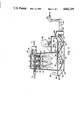
- FIG. 1 illustrates, in diagrammatic form, a spray dryer apparatus for dry scrubbing a flue gas in accordance with the process of the present invention
- FIG. 2 is enlarged elevational view showing the disposition of the supplemental filter means in the secondary drying chamber of the spray dryer apparatus of FIG. 1;
- FIG. 3 is plan view taken along line 3--3 of FIG. 2.
- the process of the present invention, and the spray drying apparatus for carrying out the process of the present invention are adaptable for use in dry scrubbing acidic gases and particulate materials from a wide variety of hot gases containing same. They are particularly adaptable for use in dry scrubbing acidic gases, such as sulfur oxides and hydrogen chloride gas, and fly ash from flue gases generated from the burning of sulfur-containing fossil fuels, such as coal and lignite, as well as the flue gases generated from incinerating household refuse or industrial waste. Accordingly, the process and apparatus of the present invention will be described hereinafter in connection with such use.
- the process and apparatus of the present invention are an improvement on the basic process for dry scrubbing sulfur oxides and particulate contaminous from a hot flue gas disclosed in U.S. Pat. No. 4,504,451, which is incorporated herein by reference, and the spray dryer apparatus described therein for carrying out the process.
- the system includes a generally vertical primary drying chamber (10) and a secondary drying chamber (100) enclosed in a single housing (2) in laterally adjacent relationship with a partition wall (48) substantially separating one chamber from the other.
- a first gas inlet duct (12) is provided in the upper region of the primary drying chamber (10) for receiving the hot flue gas containing acidic gases, such as sulfur oxides or hydrogen halide gases, into the upper portion of the primary drying chamber (10).
- hot flue gas leaving the air preheater of a fossil fuel furnace or a waste incineration furnace would have a temperature in the range of 100 to 200c.
- the upper portion of the primary drying chamber (10) serves as a spray zone.
- At least one spray nozzle or atomization means (16) is provided in the spray zone of the primary drying chamber (10) to open thereto for introducing a spray of absorbent into the hot flue gas passing through the primary drying chamber (10) from the first gas inlet (12) in the upper region thereof to the first gas outlet (14) in a lower region of the primary drying chamber (10).
- the spray means (16) are connected to a source of absorbent which comprises a solution, slurry or disperison of an alkali or alkaline reactant in a liquid such as water.
- the absorbent is atomized in the spray means (16) to form minute droplets which contain particles of the alkali or alkaline reactant.
- an atomizing gas (3) such as compressed air, is passed about the spray means (16) to assist in the atomization of the absorbent fluid and to improve the dispersion of the droplets into the hot flue gas (1) passing through the primary drying chamber (10).
- Suitable reactants include, but are not limited to, sodium carbonate, sodium bicarbonate, sodium hydroxide, sodium sesquicarbonate, calcium oxide (lime), calcium hydroxide (slaked lime), calcium carbonate (limestone), dolimite, magnesium hydroxide, and mixtures thereof.
- the reactant particle containing liquid droplets introduced into the primary drying chamber (10) through spray means (16) are entrained in the hot flue gas introduced into the upper region of the primary drying chamber (10) through a first gas inlet (12) and flowing downwardly pass the spray nozzle means (16) towards the first gas outlet (14) in the lower region of the primary drying chamber (10).
- the sulfur oxides in the gas began to react with the reactant particles entrained in the liquid droplets and are converted to acid salts of the absorbent compounds.
- the reactant liquid droplets fall downwardly through the spray drying chamber (10) in contact with the hot flue gas, they are partially dried to a tacky condition by the hot flue gas.
- An endless collecting belt (20) is supported for horizontal movement sequentially through the lower region of the primary drying chamber (10) into and through a lower region of the secondary drying chamber (100) through a gap (50) formed in the partition wall (48) which substantially separates the primary drying chamber (10) from the secondary drying chamber (100).
- the endless collecting belt (20) comprises a foraminous collecting member of the mesh type, preferably such as a woven fabric belt as disclosed in U.S. Pat. No. 4,116,756, which is incorporated therein by reference.
- the endless collecting belt (20) is disposed in a lower region of the primary drying chamber (10) between the first gas inlet (12) thereto and the first gas outlet (14) therefrom thereby effectively separating the spray zone portion of the primary drying chamber (10) from the suction chamber (19) thereof which is formed in the lowermost region of the primary drying chamber (10) beneath the endless collecting belt (20) and about the first gas outlet (14) therefrom.
- the endless collecting belt (20) extends from the primary drying chamber (10) through the gap (50) formed in the partition wall (48) into and through the secondary drying chamber (100) between the second gas inlet (112) in the upper region of the secondary drying chamber (100) and the second gas outlet (114) in a lower region of the secondary drying chamber (100).
- the endless collecting belt (20) effectively separates the secondary drying chamber (100) into a gas receiving plenum above the endless collecting belt (20) and a suction chamber (40) below the endless belt (20) in a lower most region of the secondary drying chamber (100) about the second gas outlet (112) therefrom. Therefore, the flue gas passing through the primary dryng chamber (10) and the secondary drying chamber (100) must traverse the endless belt (20) in both drying chambers.
- the collecting member preferably is in form of a belt (20) trained around rollers (22, 24, 26 and 28) for horizontal movement through the lower portion of the primary drying chamber (10) and the secondary drying chamber (100) as hereinbefore described.
- the belt (20) is driven clockwise as viewed in the drawing at a relatively slow speed, typically 1 to 5 inches per minute, by suitable means such as a motor (25) connected in driving relationship to the roller (24) by a belt drive (35) or the like.
- the belt (20) is preferably a foraminous collecting member made from a double-layered fabric woven from a monofilament synthetic material consisting of two layers of weft yarn interconnected by a plurality of warp threads as described in U.S. Pat. No. 4,116,756.
- the reactant particle containing liquid droplets are partially dried to a tacky condition by the flue gas as they pass downwardly through the drying chamber (10) and are deposited upon the collecting member (20) as the flue gas passes therethrough to enter the suction chamber (19) therebelow and pass out the first gas outlet (14) into and through the connecting gas duct (34) to the second gas inlet (112) opening to the secondary drying chamber (100).
- the process is designed such that the surfaces of the partially dried droplets are still in a tacky condition when they reach the collecting member (20), the droplets and the particulate material therein collect on the collecting member (20) and bind together at the points of contact between particles to form a mat having sufficient porosity to permit a flue gas to flow therethrough.
- the ability of the particles to form such a bond without coalescing into a substantially impermeable mass depends primarily upon the temperature and moisture content of the particles at the time they strike the collecting member (20) and/or the particles in the already accumulating mat (30) on the collecting member (20).
- the interrelationships of these variables for spray dryers employing a porous collecting member is described in more detail in U.S. Pat. Nos. 3,520,066, 3,615,723, 3,741,273 and 4,351,849, all of which are incorporated herein by reference.
- the residence time of the mat (30) in the primary spray drying zone (10) is controlled by varying the speed at which the collecting member (20) travels through the primary drying zone (10).
- the thickness of the mat increases with increasing residence time and can be up to several inches.
- the reactant particles in the mat should remain moist as long as possible to maximize the reaction with the acidic gases in the flue gas.
- the moisture content of the mat in the primary drying zone should be in the neighborhood of about 12% to 25%.
- the mat In addition to providing a bed of reactant particles for converting acidic gases in the flue gas to acid salts, the mat also serves as a filter for removing entrained particulate contaminates, such as fly ash, from the flue gas.
- the particulate contaminates are physically separated from the flue gas and become part of the mat building up on the collecting member (20) as the flue gas passes through the mat (30).
- This filtration of entrained particulate matter, both particulate matter originally in a flue gas and the reactant particles formed by reaction of the absorbent with the acidic gas reduces the required capacity of auxiliary filters for the flue gas exiting from the spray dryer (2).
- a suction blower or fan (36) is connected in the duct (34) to induce the flow of the flue gas through the mat (30) building in the primary drying chamber and provides sufficient pressure boost so that the flue gas can again pass through the mat (30) as it traverses the secondary drying chamber (100).
- the mat (30) of unreacted absorbent particles, acidic salts and other particulate matter, such as fly ash, collected on the belt (20) in the primary drying chamber (10), is traversed by the flue gas introduced into the secondary drying chamber through the second gas inlet (112).
- the flue gas again passes through the mat (30) further reaction of acidic gases therein occurs with the unreacted absorbent and any reactive ingredients in the fly ash in the mat.
- the flue gas passing through the mat (30) in the secondary drying chamber (100) flows into an exhaust chamber (40) portion of the secondary drying chamber (100) beneath the belt (20) and passes therefrom through the second gas outlet (114) to exit from the spray dryer apparatus into the flue gas outlet duct (60).
- the flue gas flowing through the gas outlet duct (60) directly to the atmosphere.
- the flue gas may be passed through a secondary particulate collector, (not shown), such as a cyclone or a bag filter, disposed in the flue gas duct (60) for removing any residual entrained particulate matter before the flue gas is exhausted to the atmosphere by the fan (62).
- the mat (30) passes into the hopper (46) wherein the mat (30) is broken into small chunks which fall through the hopper (46) to be collected for disposal.
- a portion of these chunks (44) of dried mat material may be comminuted into powder form for recycling in order to utilize any unreactant absorbent contained thereon.
- the comminuted recycle power is typically mixed with fresh powdered reactant material and dispersed in carrier liquid to form the absorbent which is introduced into the upper portion of the primary drying chamber (10) through spray means (16).
- the comminuted recycle powder may also be mixed with liquid by itself without fresh reactant to form absorbent solution.
- the mat (30) is not built-up on the belt (20). Rather, it has been found that the belt (20) must be clean without any bed build-up from previous operation. Because of pozzolonic reactions that occur in the mat (30) over several hours, mat build-up from previous operation is generally not suitable for use as an adhesive media for particulate collection during start-up, even after a short outage of only one hour. Consequently, until the mat being formed in the primary chamber (10) can move on the belt (20) into the secondary chamber (100) so as to completely span the secondary chamber (100) and begin discharging into collection trough (46), the mat (30) is largely ineffective during start-up for collecting particulate in the secondary chamber. Absent the provision of additional downstream particulate removal equipment and the cost thereof, this can be a problem in so much as a visible plume will be emitted from the stack for, potentially, up to four hours during start-up.
- an "artificial" bed is effectively provided in the secondary chamber (100) by selectively positioning gas permeable filter means (11) therein as best seen in FIGS. 2 and 3 to filter the flue gas passing therethrough until the mat (30) has built-up sufficiently on belt (20) to be effective as a particulate filter.
- the gas permeable filter means (110) serves to remove particulate material carried over from the primary drying chamber in the flue gas entering the secondary drying chanber so that the flue gas vented to the atmosphere through duct (60) will result in a low-opacity, clear plume during start-up of the spray dryer scrubber.
- the supplemental filter means (110) comprises an elongated gas permeable fabric sheet (120) which is disposed between rolls (130, 132) so as to be selectively positionable across the secondary drying chamber (100) above the belt (20).
- the fabric is stretched to span between two parallel support members (122), such as wires or ropes.
- the wires or ropes are positioned above the belt (20) in the secondary chamber (100), and the fabric is seam lapped around the wire/rope along each edge.
- the wire/rope runs from a feeder roll to a take up roll.
- the feeder roll may be provided with a guide (134), and groove (136) at either end to prevent the wire/rope from moving out-of-position.
- the gas permeable fabric is a sheet of tightly woven or felted cloth.
- the cloth should desirably have a clean draft loss of 1.0 to 2.0 inches water column at a face velocity of 150 feet/minute (i.e., actual cubic feet per minute per square foot of cloth area).
- the wire/rope (122) extends suspended above the belt (20) from the feeder roll (130) to the take-up roll (132), while the cloth (120) and the wire/rope (122) which is lapped by the cloth is wound up completely on the take-up roll (132).
- the rolls (130, 132) are stationary, that is, not turning during normal continuous operation when the mat (30) is fully developed.
- the cloth is rolled between feeder and take-up rolls only during start-up.
- the plant operator Prior to start-up, the plant operator initiates an action which rotates the take-up roll (132) and feeder roll (132) in a cooperative manner so as to selectively position the cloth (120) over the belt (20) in the secondary chamber (100).
- the forced draft and induced draft fans associated therewith (not shown), as well as the booster fan (62) are started.
- the flue gas temperature begins to rise and feed of the scrubbing solution or slurry is initiated to the spray nozzles (16) in an amount sufficient to maintain a desired gas temperature at the inlet to the booster fan (62).
- the total pressure drop in the gas from the inlet duct (72) to the primary chamber outlet plenum (19) increases.
- drive of the belt (20) is automatically initiated and the belt (20) begins to move slowly out of the primary chamber (10) into the secondary chamber (100) thereby beginning the movement of the mat (30) which has built-up on the portion of the belt (20) formerly positioned in the primary drying chamber (10) into the secondary drying chamber (100).
- the take-up of the supplemental fabric filter means is initiated by activating the feeder roll (130) and/or the take-up roll (132) to begin rewinding the cloth (120) about the take-up roll (132).
- the rotation of the rolls (130, 132) is controlled such that the movement of the cloth (120) across the secondary drying chamber (100) onto the take-up roll (132) is synchronized with the movement of the built-up mat (30) into the secondary drying chamber (100) such that as the cloth (120) is taken-up, it is replaced as a filter means by the mat (30) moving into the secondary drying chamber.
- the cloth (120) which is selectively pre-positioned across the secondary chamber (100) prior to start-up, serves to filter out at least a substantial portion of the particulate matter carried over in the flue gas from the primary drying chamber (10) during the initial stages of start-up. Then, as the built-up mat (30) moves into the secondary drying chamber (100) on belt (20) and wind-up of the cloth (120) is begun, the cloth (120) serves in conjunction with the mat (30) to ensure that nearly all of the flue gas passing through the secondary drying chamber (100) traverses either that portion of the cloth (120) still exposed in the secondary drying chamber (100) or the mat (30) entering the secondary drying chamber (100). Once the mat (30) is fully within the secondary drying chamber (100), the cloth (120) is fully withdrawn and normal filtering via the mat (30) commences.
Abstract
Description
Claims (1)
Priority Applications (2)
| Application Number | Priority Date | Filing Date | Title |
|---|---|---|---|
| US07/103,336 US4812295A (en) | 1987-10-01 | 1987-10-01 | Apparatus for dry scrubbing a hot gas and start-up process |
| EP88115316A EP0309848A3 (en) | 1987-10-01 | 1988-09-19 | Apparatus for dry scrubbing a hot gas and start-up process |
Applications Claiming Priority (1)
| Application Number | Priority Date | Filing Date | Title |
|---|---|---|---|
| US07/103,336 US4812295A (en) | 1987-10-01 | 1987-10-01 | Apparatus for dry scrubbing a hot gas and start-up process |
Publications (1)
| Publication Number | Publication Date |
|---|---|
| US4812295A true US4812295A (en) | 1989-03-14 |
Family
ID=22294635
Family Applications (1)
| Application Number | Title | Priority Date | Filing Date |
|---|---|---|---|
| US07/103,336 Expired - Lifetime US4812295A (en) | 1987-10-01 | 1987-10-01 | Apparatus for dry scrubbing a hot gas and start-up process |
Country Status (2)
| Country | Link |
|---|---|
| US (1) | US4812295A (en) |
| EP (1) | EP0309848A3 (en) |
Cited By (6)
| Publication number | Priority date | Publication date | Assignee | Title |
|---|---|---|---|---|
| US5117763A (en) * | 1990-08-21 | 1992-06-02 | Gustafson Leif V | Hydrating filter smokestack system |
| US20050214189A1 (en) * | 2004-03-29 | 2005-09-29 | Balingit Ronald F | Dry scrubber/collector |
| US20100213141A1 (en) * | 2008-10-02 | 2010-08-26 | Gryphon Environmental, Llc | Suspension liquid extraction apparatus and method |
| US9724302B2 (en) | 2010-04-09 | 2017-08-08 | Pacira Pharmaceuticals, Inc. | Method for formulating large diameter synthetic membrane vesicles |
| CN109404918A (en) * | 2018-12-06 | 2019-03-01 | 安徽航天环境工程有限公司 | Integrated waste pyrolysis gasification furnace |
| US10352239B2 (en) * | 2016-09-16 | 2019-07-16 | Southwest Research Institute | Inlet filter for gas turbine engines using disposable surface adhesive |
Families Citing this family (5)
| Publication number | Priority date | Publication date | Assignee | Title |
|---|---|---|---|---|
| FR2653447B1 (en) * | 1989-10-20 | 1991-12-27 | Bio Merieux | METHOD AND REAGENTS FOR THE DETECTION OF MICROORGANISMS. |
| JP2923208B2 (en) * | 1994-09-12 | 1999-07-26 | 三菱重工業株式会社 | Wet flue gas desulfurization equipment |
| US7531154B2 (en) | 2005-08-18 | 2009-05-12 | Solvay Chemicals | Method of removing sulfur dioxide from a flue gas stream |
| WO2007031552A1 (en) * | 2005-09-15 | 2007-03-22 | Solvay Chemicals, Inc. | Sulfur trioxide removal from a flue gas stream |
| CN104138703B (en) * | 2014-08-06 | 2016-01-20 | 山东凯盛新材料有限公司 | Between/paraphthaloyl chloride produce in waste gas treatment process and device |
Citations (7)
| Publication number | Priority date | Publication date | Assignee | Title |
|---|---|---|---|---|
| US2867324A (en) * | 1956-03-12 | 1959-01-06 | Hirs Gene | Filter apparatus |
| US2881861A (en) * | 1957-02-18 | 1959-04-14 | American Air Filter Co | Air flow seal for air filter having an expansible-contractible air cleaning web |
| US2969148A (en) * | 1957-01-18 | 1961-01-24 | Hirs Gene | Filter apparatus |
| US3261149A (en) * | 1962-09-10 | 1966-07-19 | Landis & Gyr Ag | Filter means for use in measuring the radio-activity of aerosols |
| US3783588A (en) * | 1971-12-20 | 1974-01-08 | Gen Electric | Polymer film electret air filter |
| US4351849A (en) * | 1966-05-26 | 1982-09-28 | Dec International | Foraminous mat products |
| US4504451A (en) * | 1983-07-14 | 1985-03-12 | Dec International, Inc. | Dry scrubbing oxides and particulate contaminants from hot gases |
-
1987
- 1987-10-01 US US07/103,336 patent/US4812295A/en not_active Expired - Lifetime
-
1988
- 1988-09-19 EP EP88115316A patent/EP0309848A3/en not_active Withdrawn
Patent Citations (7)
| Publication number | Priority date | Publication date | Assignee | Title |
|---|---|---|---|---|
| US2867324A (en) * | 1956-03-12 | 1959-01-06 | Hirs Gene | Filter apparatus |
| US2969148A (en) * | 1957-01-18 | 1961-01-24 | Hirs Gene | Filter apparatus |
| US2881861A (en) * | 1957-02-18 | 1959-04-14 | American Air Filter Co | Air flow seal for air filter having an expansible-contractible air cleaning web |
| US3261149A (en) * | 1962-09-10 | 1966-07-19 | Landis & Gyr Ag | Filter means for use in measuring the radio-activity of aerosols |
| US4351849A (en) * | 1966-05-26 | 1982-09-28 | Dec International | Foraminous mat products |
| US3783588A (en) * | 1971-12-20 | 1974-01-08 | Gen Electric | Polymer film electret air filter |
| US4504451A (en) * | 1983-07-14 | 1985-03-12 | Dec International, Inc. | Dry scrubbing oxides and particulate contaminants from hot gases |
Cited By (15)
| Publication number | Priority date | Publication date | Assignee | Title |
|---|---|---|---|---|
| US5117763A (en) * | 1990-08-21 | 1992-06-02 | Gustafson Leif V | Hydrating filter smokestack system |
| US20050214189A1 (en) * | 2004-03-29 | 2005-09-29 | Balingit Ronald F | Dry scrubber/collector |
| US20100213141A1 (en) * | 2008-10-02 | 2010-08-26 | Gryphon Environmental, Llc | Suspension liquid extraction apparatus and method |
| US8673156B2 (en) * | 2008-10-02 | 2014-03-18 | Gryphon Environmental, Llc | Suspension liquid extraction apparatus and method |
| US9737482B2 (en) | 2010-04-09 | 2017-08-22 | Pacira Pharmaceuticals, Inc. | Method for formulating large diameter synthetic membrane vesicles |
| US9730892B2 (en) | 2010-04-09 | 2017-08-15 | Pacira Pharmaceuticals, Inc. | Method for formulating large diameter synthetic membrane vesicles |
| US9724302B2 (en) | 2010-04-09 | 2017-08-08 | Pacira Pharmaceuticals, Inc. | Method for formulating large diameter synthetic membrane vesicles |
| US9737483B2 (en) | 2010-04-09 | 2017-08-22 | Pacira Pharmaceuticals, Inc. | Method for formulating large diameter synthetic membrane vesicles |
| US9757336B2 (en) | 2010-04-09 | 2017-09-12 | Pacira Pharmaceuticals, Inc. | Method for formulating large diameter synthetic membrane vesicles |
| US9808424B2 (en) | 2010-04-09 | 2017-11-07 | Pacira Pharmaceuticals, Inc. | Method for formulating large diameter synthetic membrane vesicles |
| US10045941B2 (en) | 2010-04-09 | 2018-08-14 | Pacira Pharmaceuticals, Inc. | Method for formulating large diameter synthetic membrane vesicles |
| US10398648B2 (en) | 2010-04-09 | 2019-09-03 | Pacira Pharmaceuticals, Inc. | Method for formulating large diameter synthetic membrane vesicles |
| US10352239B2 (en) * | 2016-09-16 | 2019-07-16 | Southwest Research Institute | Inlet filter for gas turbine engines using disposable surface adhesive |
| CN109404918A (en) * | 2018-12-06 | 2019-03-01 | 安徽航天环境工程有限公司 | Integrated waste pyrolysis gasification furnace |
| CN109404918B (en) * | 2018-12-06 | 2023-10-31 | 航天神禾(北京)环保有限公司 | Integrated waste pyrolysis gasification furnace |
Also Published As
| Publication number | Publication date |
|---|---|
| EP0309848A3 (en) | 1989-11-02 |
| EP0309848A2 (en) | 1989-04-05 |
Similar Documents
| Publication | Publication Date | Title |
|---|---|---|
| US5599508A (en) | Flue gas conditioning for the removal of acid gases, air toxics and trace metals | |
| US4956162A (en) | Process for removal of particulates and SO2 from combustion gases | |
| US4812295A (en) | Apparatus for dry scrubbing a hot gas and start-up process | |
| US5507238A (en) | Reduction of air toxics in coal combustion gas system and method | |
| US4604269A (en) | Flue gas desulfurization process | |
| US4613487A (en) | Flue gas desulfurization process | |
| US4442079A (en) | Process for removal of nitrogen oxides and sulfur oxides from waste gases | |
| CA2098045C (en) | Dry scrubber with integral particulate collection device | |
| US5250267A (en) | Particulate collection device with integral wet scrubber | |
| US4208381A (en) | Method and apparatus for cleaning waste flue gases | |
| Muzio et al. | Assessment of dry sorbent emission control technologies Part I. Fundamental processes | |
| CN205650074U (en) | Domestic waste burns combination deacidification dust pelletizing system of flue gas | |
| EP0170355B1 (en) | Emission control process for combustion flue gases | |
| US4504451A (en) | Dry scrubbing oxides and particulate contaminants from hot gases | |
| US4600568A (en) | Flue gas desulfurization process | |
| HU194981B (en) | Method and burning apparatus for separating harmful acid ases | |
| US4670238A (en) | Recycled sorbent flue gas desulfurization | |
| EP0204710A1 (en) | Method for the removal of sulphur oxides from a flue gas with a baghouse as a secondary reactor. | |
| US5439508A (en) | Process of separating halogenated dioxins and furans from exhaust gases from combustion plants | |
| US4446109A (en) | System for dry scrubbing of flue gas | |
| CA2116233A1 (en) | Method for purification of waste gases | |
| US4603037A (en) | Desulfurization of flue gas from multiple boilers | |
| JPH0722673B2 (en) | Method and device for purifying waste gas | |
| US4764348A (en) | Emission control apparatus | |
| US5624648A (en) | Method and apparatus for cleaning flue gas |
Legal Events
| Date | Code | Title | Description |
|---|---|---|---|
| AS | Assignment |
Owner name: COMBUSTION ENGINEERING, INC., WINDSOR, CT. A CORP. Free format text: ASSIGNMENT OF ASSIGNORS INTEREST.;ASSIGNOR:BRESOWAR, GERALD E.;REEL/FRAME:004811/0670 Effective date: 19870923 |
|
| STCF | Information on status: patent grant |
Free format text: PATENTED CASE |
|
| FPAY | Fee payment |
Year of fee payment: 4 |
|
| FEPP | Fee payment procedure |
Free format text: PAYOR NUMBER ASSIGNED (ORIGINAL EVENT CODE: ASPN); ENTITY STATUS OF PATENT OWNER: LARGE ENTITY |
|
| FPAY | Fee payment |
Year of fee payment: 8 |
|
| AS | Assignment |
Owner name: ABB ALSTOM POWER INC., CONNECTICUT Free format text: ASSIGNMENT OF ASSIGNORS INTEREST;ASSIGNOR:COMBUSTION ENGINEERING, INC.;REEL/FRAME:010785/0407 Effective date: 20000506 |
|
| FPAY | Fee payment |
Year of fee payment: 12 |
|
| AS | Assignment |
Owner name: ALSTOM POWER INC., CONNECTICUT Free format text: CHANGE OF NAME;ASSIGNOR:ABB ALSTOM POWER INC.;REEL/FRAME:011575/0178 Effective date: 20000622 |