US4807080A - Integrated circuit electrostatic discharge input protection - Google Patents
Integrated circuit electrostatic discharge input protection Download PDFInfo
- Publication number
- US4807080A US4807080A US07/062,211 US6221187A US4807080A US 4807080 A US4807080 A US 4807080A US 6221187 A US6221187 A US 6221187A US 4807080 A US4807080 A US 4807080A
- Authority
- US
- United States
- Prior art keywords
- transistor
- source
- pad
- drain regions
- layer
- Prior art date
- Legal status (The legal status is an assumption and is not a legal conclusion. Google has not performed a legal analysis and makes no representation as to the accuracy of the status listed.)
- Expired - Lifetime
Links
Images


Classifications
-
- H—ELECTRICITY
- H10—SEMICONDUCTOR DEVICES; ELECTRIC SOLID-STATE DEVICES NOT OTHERWISE PROVIDED FOR
- H10D—INORGANIC ELECTRIC SEMICONDUCTOR DEVICES
- H10D89/00—Aspects of integrated devices not covered by groups H10D84/00 - H10D88/00
- H10D89/60—Integrated devices comprising arrangements for electrical or thermal protection, e.g. protection circuits against electrostatic discharge [ESD]
- H10D89/601—Integrated devices comprising arrangements for electrical or thermal protection, e.g. protection circuits against electrostatic discharge [ESD] for devices having insulated gate electrodes, e.g. for IGFETs or IGBTs
- H10D89/811—Integrated devices comprising arrangements for electrical or thermal protection, e.g. protection circuits against electrostatic discharge [ESD] for devices having insulated gate electrodes, e.g. for IGFETs or IGBTs using FETs as protective elements
Definitions
- This invention relates generally to techniques and devices for protecting electronic circuits from high voltage spikes resulting from electrostatic discharges from handling of packaged integrated circuits.
- MOS metal-oxide-silicon
- the goal in providing such a protection circuit is to shunt the undesired voltage spikes around the sensitive field effect transistors without affecting the operation of the transistor.
- Early field effect transistors had a relatively thick gate oxide, so simple protection techniques were satisfactory.
- the gate oxides have become thinner as part of an improvement in integrated circuit technology, the electrostatic voltage level that could harm the more delicate gate oxide have become significantly lower.
- protection circuits have become more complicated in order to assure that only a lower voltage reached the transistor being protected when the circuit was subjected to a high voltage electrostatic discharge spike.
- the improving technology was allowing the size of integrated circuits to be shrunk in order to increase the number of circuits that can be produced at one time on a single wafer.
- the one circuit part that could not be shrunk was the bonding pad since a certain amount of area is required for bonding leads to the circuit chip. If a complicated electrostatic discharage circuit is provided with each input pad, limitations are presented in packing the pads together, and otherwise shrinking the circuit in order to take full advantage of improving process technology.
- a first protective transistor is formed adjacent the input pad in a manner to prevent damaging high current densities from flowing when the protection circuit operates, and also to provide a protection against any aluminum of a circuit conductor that might melt during such a discharge.
- This protective transistor is formed, according to one embodiment, by a pair of elongated source and drain diffusions that are contacted by solid, elongated aluminum conductors through a layer of conductive polysilicon. The corners of the conductors and diffusions are rounded and otherwise arranged to assure that current density flowing in the transistor is substantially uniform when operating to shunt the high current produced by electrostatic voltage discharge, thereby to prevent high current concentration that can permanently the device.
- the layer of polysilicon disposed between the aluminum conductor in the source and drain diffusions provides a barrier to any melting aluminum from penetrating through the diffusion into the substrate, which will permanently damage the circuit if allowed to happen.
- the width of the channel between the source and drain diffusions is made as small as possible.
- a width of from about three microns up to about six microns can provide an initial protective transistor that shunts enough current around the protective device by a reverse breakdown to limit the voltage seen by the protective device to less than 10 volts.
- This voltage limitation is accomplished with a single transistor, no second thin gate transistor, as is more conventionally additionally employed, being necessary.
- a second thin gate oxide transistor is provided to reduce the voltage further than the first transistor allows to pass towards the protective circuits.
- FIG. 1 is a plan view of one wire bonding pad and associated protective circuitry according to a preferred embodiment of the present invention
- FIG. 2 is a cross-sectional view of the circuit structure of FIG. 1, taken through Section 2--2 thereof;
- FIG. 3 is a cross-sectional view of the circuit structure of FIG. 1, taken through Section 3--3 thereof;
- FIG. 4 is a cross-sectional view of the circuit structure of FIG. 1, taken through Section 4--4 thereof;
- FIG. 5 is an equivalent schematic circuit of the protection circuit shown laid out in FIGS. 1-4;
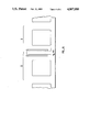
- FIG. 6 shows an arrangement of multiple units of a wire bonding pad and associated protective circuits.
- the example protective circuit structure of FIGS. 1-5 which illustrates many of the various aspects of the present invention, is an NMOS type of circuit.
- the various aspects of the present invention are not limited to that type of circuit structure, but rather have applicability to other types, such as PMOS and various types of CMOS circuitry.
- the protective circuit structure illustrated by FIGS. 1-5 has been found to operate satisfactorily when up to 5,000 volts is applied to an input pad, before the protective circuit itself fails. Within that range of up to 5,000 volts, the circuit being protected sees 10 volts or less. With this low voltage, the protected circuit can have a gate oxide thickness of from 150 Angstroms to 250 Angstroms without danger of being irreparably damaged by such a large electrostatic discharge voltage applied to the circuit.
- a wire bonding pad 11 is generally of rectilinear shape with one edge 13 serving as a gate electrode of a first protective transistor M1, a thick film device.
- An elongated N+ diffusion 15 in a P doped silicon semiconductor substrate 17 is positioned under the pad 11 adjacent its edge 13.
- An elongated source N+ diffusion 19 a location extending beyond the edge 13 and under a voltage supply bus 21, in this case the V ss .
- the elongated drain and source diffusions 15 and 19 form a channel 23 in the substrate 17.
- the input signal desired to be communicated from the pad 11 to a protective circuit 25 is passed through a diffused resistor 27.
- An equivalent circuit of the diffused resistor 27 (FIG. 5) indicates, in addition to the series resistance, the formation of a capacitance coupling with the substrate 17 and a P-N junction in the form of a normally reverse biased diode. That signal is connected to a second protective transistor M2, this one being of a thin gate oxide type.
- the resistor diffusion 27 is extended into an elongated drain diffusion 29 of the transistor M2.
- the drain 29 is electrically connected to an elongated conductor 31 by a series of circular contacts, such as contact 33.
- An end 35 of the conductor 31 is extended (not shown) to connect with the operating circuit 25 that is being protected against the effects of electrostatic voltage discharge.
- the second transistor M2 also includes an elongated source diffusion 37 that is connected to the V ss bus 21 by a series of circular contacts, such as the contact 39.
- An elongated polysilicon gate 41 is also connected to the V ss bus 21 by pins at each end of the gate, such as contact 43.
- the electrical contact between the pad 11 and the drain diffusion 15 is made by an elongated depression 51 of the pad aluminum to form an elongated contact through a layer 67 of pyrox and an elongated layer of conductive polysilicon material 53.
- connection between the V ss bus 21 and the source diffusion 19 is made through an elongated depression 55 of the aluminum conductor 21 to form an elongated contact through the pyrox layer 67 and an intermediate conductive polysilicon layer 57.
- This diffusion contact structure of the protective transistor M1 has a beneficial effect of increasing the upper voltage limit that the protective circuit can handle without destruction.
- a common form of permanent damage to a protective circuit is a partial melting of an aluminum conductor, usually at a point where the conductor is attached to a diffusion, in response to the high currents that are generated by high electrostatic discharge voltages. The melted aluminum then migrates into the diffusion along the direction of current flow in the transistor. Once that aluminum migrates into the substrate of the device, the device is irreversibly damaged. Therefore, the use of the polysilicon layers 53 and 57 as a barrier between the aluminum conductors and the respective diffused region increases the temperatures and durations of high current that are required to cause such damage, thereby increasing the maximum electrostatic discharge voltage that the circuit can repetitively handle without damage.
- the relative dimensions of the contact, polysilicon layer and diffusion also play a part in maximizing the voltage that can be handled. Because it is believed that the molten aluminum moves laterally as well vertically, the width of the polysilicon pads 53 and 57 is made to be wider than the width of their respective contacts 51 and 55. Similarly, the width of their respective diffusions 15 and 19 is made to be significantly wider than that of the polysilicon layers 53 and 57.
- a thin layer 54 of oxide has openings etched to provide openings slightly larger than the size of the self-aligned polysilicon layers 53 and 57.
- Another goal of the specific layout of the transistor M1 that is illustrated in FIGS. 1 and 2 is to make the density of electrical currents flowing between the drain and source regions 15 and 19 to be as uniform as possible Care has been taken to avoid any "hot spots" from being generated and thus causing permanent damage to the circuit at relatively low currents and electrostatic voltages.
- Current density is made uniform by taking care that there are no sharp corners in the current paths, rounded corners being utilized with the conductors and polysilicon layers.
- the conductors and their respective polysilicon layers contact the diffusions continuously along most of their lengths, rather than using a circular or some other shaped non-continuous contact.
- the edges of the diffusions 15 and 19 adjacent the channel 23 are made to be as precisely parallel as possible.
- Field oxide 61 is grown over the channel 23 region. Regions 63 and 65 of field oxide are also grown on opposite sides of the drain and source diffusions.
- the layer of pyrox 67 is provided to insulate the conductive layers from other portions of the circuit structure. It will be noted that the thickness of the pyrox 67 and of the field oxide 61 keeps the gate portion 13 of the transistor spaced a significant distance from the channel 23.
- a width of the channel 23 of 6 microns or less has resulted in such a voltage to be 10 volts or less, when an electrostatic voltage of thousands of volts is impressed on the circuit.
- a width of the channel 23 of 3-4 microns appears to provide very satisfactory protection for delicate transistors having gates as thin as in the range of from 150 Angstroms to 250 Angstroms.
- the second transistor M2 can be dispensed with altogether.
- a second stage protective transistor is often used in protective circuits to reduce the voltage beyond that which the initial transistor can do by itself.
- the diffused resistor 27 remains desirable, however, in order to provide some time delay in an electrostatically induced voltage rise in order that the first transistor M1 will have an opportunity to respond to that voltage edge.
- the value of such a diffused resistor 27 need only be in a range of 100-1,000 ohms.
- the second transistor M2 is provided.
- This transistor is a thin gate device, as can be seen by the cross-sectional view of FIG. 3.
- Elongated drain 29 and source 37 are spaced apart to form a channel under an elongated, conductive polysilicon gate 41.
- the gate 41 is electrically tied to the V ss bus 21.
- a cross-sectional view of FIG. 4 of an end of the transistor M2 shows a wide end of the gate 41 in contact with the conductor 21 and separated from the substrate 21 by a field oxide layer 42.
- the layout of the transistors M1 and M2 shown in FIG. 1 is designed to conserve space on integrated circuit chips and to allow a number of input paths and their associated protective circuitry to be grouped together in very little space.
- An example of a multiple pad structure is given in FIG. 6, wherein only the conductive metal elements of such circuits are shown.
- a first circuit 71 is that described with respect to FIGS. 1-5.
- a second circuit 73 having all the same characteristics, is laid out immediately adjacent the circuit 71 and is a mirror image thereof.
- the second transistor M2 of each of the input pads/circuits 71 and 73 now can share common elements, including a single V ss bus that is now made to be twice as wide as that used with a single circuit layout of FIG. 1.
- each of the adjacent M2 transistors are also combined into a single diffusion that is twice as wide as that utilized in the FIG. 1 layout.
- On opposite sides of the pad/protective circuit 71 and 73 are similar pads and protective circuits which are again mere images of those against which they are positioned. The result is a very efficient use of space, allowing the pads themselves to be packed quite closely together. Of course, if the second transistor M2 is not utilized, then the pads can be packed even tighter together.
Landscapes
- Semiconductor Integrated Circuits (AREA)
- Metal-Oxide And Bipolar Metal-Oxide Semiconductor Integrated Circuits (AREA)
Abstract
Description
Claims (10)
Priority Applications (1)
| Application Number | Priority Date | Filing Date | Title |
|---|---|---|---|
| US07/062,211 US4807080A (en) | 1987-06-15 | 1987-06-15 | Integrated circuit electrostatic discharge input protection |
Applications Claiming Priority (1)
| Application Number | Priority Date | Filing Date | Title |
|---|---|---|---|
| US07/062,211 US4807080A (en) | 1987-06-15 | 1987-06-15 | Integrated circuit electrostatic discharge input protection |
Publications (1)
| Publication Number | Publication Date |
|---|---|
| US4807080A true US4807080A (en) | 1989-02-21 |
Family
ID=22040932
Family Applications (1)
| Application Number | Title | Priority Date | Filing Date |
|---|---|---|---|
| US07/062,211 Expired - Lifetime US4807080A (en) | 1987-06-15 | 1987-06-15 | Integrated circuit electrostatic discharge input protection |
Country Status (1)
| Country | Link |
|---|---|
| US (1) | US4807080A (en) |
Cited By (19)
| Publication number | Priority date | Publication date | Assignee | Title |
|---|---|---|---|---|
| US4962320A (en) * | 1988-07-29 | 1990-10-09 | Kabushiki Kaisha Toshiba | Input protection circuit for MOS device |
| US5066999A (en) * | 1989-10-23 | 1991-11-19 | Micron Technology, Inc. | Resistor under wirebond pad |
| US5285095A (en) * | 1991-06-13 | 1994-02-08 | Nec Corporation | Semiconductor integrated circuit with input protective transistor effective against electric surge |
| US5301081A (en) * | 1992-07-16 | 1994-04-05 | Pacific Monolithics | Input protection circuit |
| US5436183A (en) * | 1990-04-17 | 1995-07-25 | National Semiconductor Corporation | Electrostatic discharge protection transistor element fabrication process |
| FR2719158A1 (en) * | 1994-02-11 | 1995-10-27 | Mitel Corp | Input circuit to protect a monolithic integrated circuit. |
| US5477407A (en) * | 1993-12-17 | 1995-12-19 | Fujitsu Limited | Protection circuit for protecting a semiconductor device from a voltage surge |
| US5572394A (en) * | 1995-04-06 | 1996-11-05 | Industrial Technology Research Institute | CMOS on-chip four-LVTSCR ESD protection scheme |
| US5579200A (en) * | 1993-01-29 | 1996-11-26 | Zilog, Inc. | Electrostatic discharge protection for metal-oxide-silicon feedback elements between pins |
| US5594611A (en) * | 1994-01-12 | 1997-01-14 | Lsi Logic Corporation | Integrated circuit input/output ESD protection circuit with gate voltage regulation and parasitic zener and junction diode |
| US5637900A (en) * | 1995-04-06 | 1997-06-10 | Industrial Technology Research Institute | Latchup-free fully-protected CMOS on-chip ESD protection circuit |
| US5754380A (en) * | 1995-04-06 | 1998-05-19 | Industrial Technology Research Institute | CMOS output buffer with enhanced high ESD protection capability |
| US5793068A (en) * | 1994-01-03 | 1998-08-11 | Texas Instruments Incorporated | Compact gate array |
| US5852315A (en) * | 1995-04-06 | 1998-12-22 | Ind Tech Res Inst | N-sided polygonal cell layout for multiple cell transistor |
| US6477023B1 (en) * | 2000-07-12 | 2002-11-05 | United Microelectronics Corp. | Electrostatic discharge protection apparatus |
| US20040129983A1 (en) * | 2003-01-03 | 2004-07-08 | Micrel, Incorporated | Thick gate oxide transistor and electrostatic discharge protection utilizing thick gate oxide transistors |
| US20040137690A1 (en) * | 2003-01-03 | 2004-07-15 | Shekar Mallikarjunaswamy | Insulated gate bipolar transistor and electrostatic discharge cell protection utilizing insulated gate bipolar transistors |
| US6864537B1 (en) | 2003-01-03 | 2005-03-08 | Micrel, Incorporated | Thick gate oxide transistor and electrostatic discharge protection utilizing thick gate oxide transistors |
| US20080044969A1 (en) * | 2003-07-17 | 2008-02-21 | Ming-Dou Ker | Turn-on-efficient bipolar structures with deep n-well for on-chip esd protection |
Citations (3)
| Publication number | Priority date | Publication date | Assignee | Title |
|---|---|---|---|---|
| US4541002A (en) * | 1981-06-30 | 1985-09-10 | Fujitsu Limited | Protective device for a semiconductor integrated circuit including double polysilicon resistor |
| WO1986000697A1 (en) * | 1984-07-02 | 1986-01-30 | Societe Nationale Industrielle Aerospatiale | Method and device for determining the position of a movable member by means of elements having variable optical properties |
| US4605980A (en) * | 1984-03-02 | 1986-08-12 | Zilog, Inc. | Integrated circuit high voltage protection |
-
1987
- 1987-06-15 US US07/062,211 patent/US4807080A/en not_active Expired - Lifetime
Patent Citations (3)
| Publication number | Priority date | Publication date | Assignee | Title |
|---|---|---|---|---|
| US4541002A (en) * | 1981-06-30 | 1985-09-10 | Fujitsu Limited | Protective device for a semiconductor integrated circuit including double polysilicon resistor |
| US4605980A (en) * | 1984-03-02 | 1986-08-12 | Zilog, Inc. | Integrated circuit high voltage protection |
| WO1986000697A1 (en) * | 1984-07-02 | 1986-01-30 | Societe Nationale Industrielle Aerospatiale | Method and device for determining the position of a movable member by means of elements having variable optical properties |
Non-Patent Citations (2)
| Title |
|---|
| Roundtree et al., "NMOS Protection Circuitry," IEEE Transactions on Electron Devices, vol. ED-32, No. 5, May 1985. |
| Roundtree et al., NMOS Protection Circuitry, IEEE Transactions on Electron Devices, vol. ED 32, No. 5, May 1985. * |
Cited By (26)
| Publication number | Priority date | Publication date | Assignee | Title |
|---|---|---|---|---|
| US4962320A (en) * | 1988-07-29 | 1990-10-09 | Kabushiki Kaisha Toshiba | Input protection circuit for MOS device |
| US5066999A (en) * | 1989-10-23 | 1991-11-19 | Micron Technology, Inc. | Resistor under wirebond pad |
| US5436183A (en) * | 1990-04-17 | 1995-07-25 | National Semiconductor Corporation | Electrostatic discharge protection transistor element fabrication process |
| US5285095A (en) * | 1991-06-13 | 1994-02-08 | Nec Corporation | Semiconductor integrated circuit with input protective transistor effective against electric surge |
| US5301081A (en) * | 1992-07-16 | 1994-04-05 | Pacific Monolithics | Input protection circuit |
| US5579200A (en) * | 1993-01-29 | 1996-11-26 | Zilog, Inc. | Electrostatic discharge protection for metal-oxide-silicon feedback elements between pins |
| US5477407A (en) * | 1993-12-17 | 1995-12-19 | Fujitsu Limited | Protection circuit for protecting a semiconductor device from a voltage surge |
| US5793068A (en) * | 1994-01-03 | 1998-08-11 | Texas Instruments Incorporated | Compact gate array |
| US5815360A (en) * | 1994-01-12 | 1998-09-29 | Lsi Logic Corporation | Integrated circuit input/output ESD protection circuit with gate voltage regulation and parasitic zener and junction diode |
| US5594611A (en) * | 1994-01-12 | 1997-01-14 | Lsi Logic Corporation | Integrated circuit input/output ESD protection circuit with gate voltage regulation and parasitic zener and junction diode |
| US5707886A (en) * | 1994-01-12 | 1998-01-13 | Lsi Logic Corporation | Process for providing electrostatic discharge protection to an integrated circuit output pad |
| FR2719158A1 (en) * | 1994-02-11 | 1995-10-27 | Mitel Corp | Input circuit to protect a monolithic integrated circuit. |
| US5754380A (en) * | 1995-04-06 | 1998-05-19 | Industrial Technology Research Institute | CMOS output buffer with enhanced high ESD protection capability |
| US5637900A (en) * | 1995-04-06 | 1997-06-10 | Industrial Technology Research Institute | Latchup-free fully-protected CMOS on-chip ESD protection circuit |
| US5572394A (en) * | 1995-04-06 | 1996-11-05 | Industrial Technology Research Institute | CMOS on-chip four-LVTSCR ESD protection scheme |
| US5852315A (en) * | 1995-04-06 | 1998-12-22 | Ind Tech Res Inst | N-sided polygonal cell layout for multiple cell transistor |
| US6477023B1 (en) * | 2000-07-12 | 2002-11-05 | United Microelectronics Corp. | Electrostatic discharge protection apparatus |
| US6861711B2 (en) | 2003-01-03 | 2005-03-01 | Micrel, Incorporated | Thick gate oxide transistor and electrostatic discharge protection utilizing thick gate oxide transistors |
| US20040137690A1 (en) * | 2003-01-03 | 2004-07-15 | Shekar Mallikarjunaswamy | Insulated gate bipolar transistor and electrostatic discharge cell protection utilizing insulated gate bipolar transistors |
| US20040129983A1 (en) * | 2003-01-03 | 2004-07-08 | Micrel, Incorporated | Thick gate oxide transistor and electrostatic discharge protection utilizing thick gate oxide transistors |
| US6864537B1 (en) | 2003-01-03 | 2005-03-08 | Micrel, Incorporated | Thick gate oxide transistor and electrostatic discharge protection utilizing thick gate oxide transistors |
| US6888710B2 (en) | 2003-01-03 | 2005-05-03 | Micrel, Incorporated | Insulated gate bipolar transistor and electrostatic discharge cell protection utilizing insulated gate bipolar transistors |
| US20050139958A1 (en) * | 2003-01-03 | 2005-06-30 | Micrel, Incorporated | Thick gate oxide transistor and electrostatic discharge protection utilizing thick gate oxide transistors |
| US20050167753A1 (en) * | 2003-01-03 | 2005-08-04 | Micrel, Incorporated | Insulated gate bipolar transistor and electrostatic discharge cell protection utilizing insulated gate bipolar tansistors |
| US20080044969A1 (en) * | 2003-07-17 | 2008-02-21 | Ming-Dou Ker | Turn-on-efficient bipolar structures with deep n-well for on-chip esd protection |
| US7494854B2 (en) | 2003-07-17 | 2009-02-24 | Transpacific Ip, Ltd. | Turn-on-efficient bipolar structures for on-chip ESD protection |
Similar Documents
| Publication | Publication Date | Title |
|---|---|---|
| US4807080A (en) | Integrated circuit electrostatic discharge input protection | |
| EP0161983B1 (en) | Input protection arrangement for vlsi integrated circuit devices | |
| US4605980A (en) | Integrated circuit high voltage protection | |
| US4745450A (en) | Integrated circuit high voltage protection | |
| JP2914292B2 (en) | Semiconductor device | |
| US4811155A (en) | Protection circuit for a semiconductor integrated circuit having bipolar transistors | |
| EP0324185B1 (en) | Input protecting circuit in use with a MOS semiconductor device | |
| JPH09321220A (en) | Microelectronic device with thin film electrostatic discharge protection structure | |
| JPH06332011A (en) | Semiconductor integrated substrate and semiconductor device | |
| EP0068844B1 (en) | A protective device for a semiconductor integrated circuit | |
| US4819046A (en) | Integrated circuit with improved protective device | |
| JP2822915B2 (en) | Semiconductor device | |
| EP0371663B1 (en) | Integrated circuit output buffer having improved ESD protection | |
| JP3549916B2 (en) | Overvoltage protection circuit | |
| JP2954153B1 (en) | Semiconductor integrated circuit | |
| EP0198468B1 (en) | Protective device for integrated circuit | |
| JPH0821630B2 (en) | Semiconductor device | |
| JPH0228266B2 (en) | ||
| JP2776569B2 (en) | Semiconductor device | |
| JPS63291470A (en) | Protective circuit for semiconductor integrated circuit device | |
| KR0177394B1 (en) | Input part of semiconductor device | |
| JPS61179576A (en) | Semiconductor integrated circuit device | |
| JPS61232658A (en) | integrated circuit device | |
| KR19990057367A (en) | Semiconductor device with antistatic device | |
| KR920004367B1 (en) | Semiconductor Input Pad Static Protection Device |
Legal Events
| Date | Code | Title | Description |
|---|---|---|---|
| AS | Assignment |
Owner name: ZILOG, INC., CAMPBELL, CALIFORNIA, A CORP. OF CA Free format text: ASSIGNMENT OF ASSIGNORS INTEREST.;ASSIGNOR:CLARK, STEPHEN E.;REEL/FRAME:004742/0364 Effective date: 19870610 Owner name: ZILOG, INC.,CALIFORNIA Free format text: ASSIGNMENT OF ASSIGNORS INTEREST;ASSIGNOR:CLARK, STEPHEN E.;REEL/FRAME:004742/0364 Effective date: 19870610 |
|
| STCF | Information on status: patent grant |
Free format text: PATENTED CASE |
|
| FEPP | Fee payment procedure |
Free format text: PAYOR NUMBER ASSIGNED (ORIGINAL EVENT CODE: ASPN); ENTITY STATUS OF PATENT OWNER: LARGE ENTITY |
|
| FPAY | Fee payment |
Year of fee payment: 4 |
|
| FPAY | Fee payment |
Year of fee payment: 8 |
|
| AS | Assignment |
Owner name: STATE STREET BANK AND TRUST COMPANY, CONNECTICUT Free format text: SECURITY INTEREST;ASSIGNOR:ZILOG, INC.;REEL/FRAME:009089/0001 Effective date: 19980227 |
|
| FPAY | Fee payment |
Year of fee payment: 12 |