US4800371A - Freeze alarm - Google Patents
Freeze alarm Download PDFInfo
- Publication number
- US4800371A US4800371A US06/900,319 US90031986A US4800371A US 4800371 A US4800371 A US 4800371A US 90031986 A US90031986 A US 90031986A US 4800371 A US4800371 A US 4800371A
- Authority
- US
- United States
- Prior art keywords
- switch
- pipe
- tested
- switch means
- pipes
- Prior art date
- Legal status (The legal status is an assumption and is not a legal conclusion. Google has not performed a legal analysis and makes no representation as to the accuracy of the status listed.)
- Expired - Fee Related
Links
Images
Classifications
-
- G—PHYSICS
- G08—SIGNALLING
- G08B—SIGNALLING OR CALLING SYSTEMS; ORDER TELEGRAPHS; ALARM SYSTEMS
- G08B21/00—Alarms responsive to a single specified undesired or abnormal condition and not otherwise provided for
- G08B21/18—Status alarms
- G08B21/182—Level alarms, e.g. alarms responsive to variables exceeding a threshold
-
- E—FIXED CONSTRUCTIONS
- E03—WATER SUPPLY; SEWERAGE
- E03B—INSTALLATIONS OR METHODS FOR OBTAINING, COLLECTING, OR DISTRIBUTING WATER
- E03B7/00—Water main or service pipe systems
- E03B7/09—Component parts or accessories
- E03B7/10—Devices preventing bursting of pipes by freezing
-
- G—PHYSICS
- G01—MEASURING; TESTING
- G01K—MEASURING TEMPERATURE; MEASURING QUANTITY OF HEAT; THERMALLY-SENSITIVE ELEMENTS NOT OTHERWISE PROVIDED FOR
- G01K3/00—Thermometers giving results other than momentary value of temperature
- G01K3/005—Circuits arrangements for indicating a predetermined temperature
-
- Y—GENERAL TAGGING OF NEW TECHNOLOGICAL DEVELOPMENTS; GENERAL TAGGING OF CROSS-SECTIONAL TECHNOLOGIES SPANNING OVER SEVERAL SECTIONS OF THE IPC; TECHNICAL SUBJECTS COVERED BY FORMER USPC CROSS-REFERENCE ART COLLECTIONS [XRACs] AND DIGESTS
- Y10—TECHNICAL SUBJECTS COVERED BY FORMER USPC
- Y10T—TECHNICAL SUBJECTS COVERED BY FORMER US CLASSIFICATION
- Y10T137/00—Fluid handling
- Y10T137/1189—Freeze condition responsive safety systems
Definitions
- This invention relates to a temperature sensing alarm circuit and, more particularly, to such a circuit for sounding an alarm when water in a pipe being tested reaches a temperature of from about 4° C. to about 5° C.
- an electric circuit is provided with a switch that senses the ambient air temperature in the vicinity of a pipe to be tested.
- the switch is preferably an electroceramic reed switch because of the minimum temperature tolerance and because of its relatively long life.
- bimetallic switches may also be used.
- the switch is set to activate an alarm when the water in the pipe being tested reaches about 4° C. to about 5° C. Because the pipe acts as a heat insulator the ambient air temperature is already below freezing temperature. It has been determined by experiment that the actual ambient air temperature is in the range of about -1° C. to about -15° C. when the temperature of the water in the pipe is from 4° C. to 5° C. This permits sufficient time for remedial action to be taken. In many instances this consists of opening a valve to permit water to flow through the pipe or pipes in question.
- the electric circuit is contained within a housing that is sufficiently perforated to permit the sensing of the ambient air temperature solely by radiation.
- the housing may be provided with Velcro straps to secure the housing to a pipe to be tested even though heat conduction to the housing and contained circuit is not required for proper operation.
- the alarm may be either or both at the site of testing and/or at a remote location.
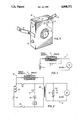
- FIG. 1 is a schematic drawing of a D.C. circuit used in the present invention
- FIG. 2 is a schematic drawing of an A.C. circuit used in the present invention.
- FIG. 3 is a perspective view of a housing for the circuits of the present invention.
- FIG. 1 of the drawings there is disclosed a direct current alarm circuit indicated generally at 5 in which an electro-ceramic temperature sensing switch 6 is employed.
- This is a reed switch which is normally open but is illustrated in its closed position.
- the temperature sensing reed switch 6 is provided with a ferrite toroidal central portion with toroid magnets disposed on opposite sides thereof.
- the switch is normally open but is shown in its closed position or alarm sounding position.
- a single throw momentary switch 7 is placed as a shunt across the temperature sensing switch 6, the momentary pressing of which makes contact to complete the circuit and test the alarm.
- a D.C. power supply is shown at 9 to provide a voltage of 1.5 volts or higher in order to sound the alarm by actuation of a buzzer 10.
- the electro-ceramic temperature switch 6 is prefabricated to close within the temperature range of -1° C. to -15° C. depending upon the known characteristics of the pipe being tested which includes its material, size and wall thickness. At the selected temperature the contacts of the switch close the actuate buzzer 10. This buzzer may be located on site or at a remote location or in both locations, as desired. This permits sufficient time for remedial action to be taken which in most instances consists of opening a valve to permit water to flow through the pipe or pipes in question.
- This circuit includes a temperature sensing switch 6 which is an electro-ceramic reed switch as in the previous embodiment.
- This circuit also includes a momentary test switch 22 and is powered by an AC power supply 23, usually 110 volts.
- An on/off switch 24 is provided in series with a line fuse 26.
- the circuit includes a flasher element 27 and a light 28 to yield a warning on the site.
- the circuit is provided with a step down transformer 29 which provides a voltage of a desired amount in a secondary circuit generally designated 33 to activate relay 30 which controls contact 31 and a buzzer 32. Once again, the buzzer 32 may be located at a remote position where surveillance is more convenient.
- a water temperature drop in the pipe to be tested to about 4° C. to about 5° C. triggers temperature sensing switch 6 of the primary circuit 20 causing current to flow through the primary of step down transformer 29 which is coupled to the secondary thereof in secondary circuit 33.
- buzzer 32 is actuated in the secondary circuit 33.
- a housing is indicated generally at 38 for containing the previously described circuitry.
- This housing is provided with a sufficient number of apertures or holes 34 to permit the ambient air temperature to be sensed by the temperature sensing switch within the housing 38.
- the housing may be provided with Velcro strap means 40 in order to attach the housing 38 to a pipe to be tested.
- Velcro is a trademark of Velcro, Inc., of Manchester, N.H., for separable fasteners, namely, hook and loop type fasteners.
- the flashing light illustrated in FIG. 2 is used in areas such as well houses, out buildings, or areas containing water pipes which are in view, but where no person is in close proximity.
- a test switch is placed in the circuit such as is illustrated at 22 which is actually a momentary contact switch shunting the temperature sensor and turning on the alarm circuit.
- the freeze alarm can be placed in any vertical or horizontal position and still be activated at the desired temperature.
- bimetallic switch means may be used as the temperature sensing means.
Landscapes
- Physics & Mathematics (AREA)
- General Physics & Mathematics (AREA)
- Business, Economics & Management (AREA)
- Emergency Management (AREA)
- Health & Medical Sciences (AREA)
- Life Sciences & Earth Sciences (AREA)
- Engineering & Computer Science (AREA)
- Hydrology & Water Resources (AREA)
- Public Health (AREA)
- Water Supply & Treatment (AREA)
- Emergency Alarm Devices (AREA)
Abstract
An apparatus for protecting pipes subjected to freezing temperatures. An electric circuit is provided with a switch that senses the ambient air temperature in the vicinity of a pipe to be tested. The switch is set to activate an alarm when the water in the pipe reaches about 4° C. to about 5° C. The electric circuit is contained within a housing that is perforated to permit the sensing of the ambient air temperature. The housing may be provided with velcro straps to secure the housing to a pipe to be tested.
Description
This application is a continuation-in-part of Ser. No. 701,032, filed Feb. 12, 1985 now abandoned.
This invention relates to a temperature sensing alarm circuit and, more particularly, to such a circuit for sounding an alarm when water in a pipe being tested reaches a temperature of from about 4° C. to about 5° C.
Heretofore, it has been known to provide frost warnings for pipes by mechanical means which relied upon expansion of water in an auxiliary narrow diameter pipe to protect a larger diameter pipe. Such a device is shown in U.S. Pat. No. 1,446,783 Calinaud issued Feb. 27, 1923. Not only is such a device expensive to install but also it is relatively unreliable and can result in burst pipes before remedial action can be taken.
In accordance with the present invention the shortcomings and limitations of the known prior art are effectively overcome. In particular, an electric circuit is provided with a switch that senses the ambient air temperature in the vicinity of a pipe to be tested. The switch is preferably an electroceramic reed switch because of the minimum temperature tolerance and because of its relatively long life. However, bimetallic switches may also be used. The switch is set to activate an alarm when the water in the pipe being tested reaches about 4° C. to about 5° C. Because the pipe acts as a heat insulator the ambient air temperature is already below freezing temperature. It has been determined by experiment that the actual ambient air temperature is in the range of about -1° C. to about -15° C. when the temperature of the water in the pipe is from 4° C. to 5° C. This permits sufficient time for remedial action to be taken. In many instances this consists of opening a valve to permit water to flow through the pipe or pipes in question.
The electric circuit is contained within a housing that is sufficiently perforated to permit the sensing of the ambient air temperature solely by radiation. For the sake of convenience, the housing may be provided with Velcro straps to secure the housing to a pipe to be tested even though heat conduction to the housing and contained circuit is not required for proper operation. The alarm may be either or both at the site of testing and/or at a remote location.
The inherent advantages and improvements of the present invention will become readily apparent by referring to the following detailed description of the invention and by reference to the drawings wherein:
FIG. 1 is a schematic drawing of a D.C. circuit used in the present invention;
FIG. 2 is a schematic drawing of an A.C. circuit used in the present invention; and
FIG. 3 is a perspective view of a housing for the circuits of the present invention.
Referring now to FIG. 1 of the drawings, there is disclosed a direct current alarm circuit indicated generally at 5 in which an electro-ceramic temperature sensing switch 6 is employed. This is a reed switch which is normally open but is illustrated in its closed position. The temperature sensing reed switch 6 is provided with a ferrite toroidal central portion with toroid magnets disposed on opposite sides thereof. The switch is normally open but is shown in its closed position or alarm sounding position. A single throw momentary switch 7 is placed as a shunt across the temperature sensing switch 6, the momentary pressing of which makes contact to complete the circuit and test the alarm. A D.C. power supply is shown at 9 to provide a voltage of 1.5 volts or higher in order to sound the alarm by actuation of a buzzer 10.
The electro-ceramic temperature switch 6 is prefabricated to close within the temperature range of -1° C. to -15° C. depending upon the known characteristics of the pipe being tested which includes its material, size and wall thickness. At the selected temperature the contacts of the switch close the actuate buzzer 10. This buzzer may be located on site or at a remote location or in both locations, as desired. This permits sufficient time for remedial action to be taken which in most instances consists of opening a valve to permit water to flow through the pipe or pipes in question.
Referring now to FIG. 2 of the drawngs, there is illustrated an AC circuit indicated generally at 20. This circuit includes a temperature sensing switch 6 which is an electro-ceramic reed switch as in the previous embodiment. This circuit also includes a momentary test switch 22 and is powered by an AC power supply 23, usually 110 volts. An on/off switch 24 is provided in series with a line fuse 26. The circuit includes a flasher element 27 and a light 28 to yield a warning on the site. The circuit is provided with a step down transformer 29 which provides a voltage of a desired amount in a secondary circuit generally designated 33 to activate relay 30 which controls contact 31 and a buzzer 32. Once again, the buzzer 32 may be located at a remote position where surveillance is more convenient.
A water temperature drop in the pipe to be tested to about 4° C. to about 5° C. triggers temperature sensing switch 6 of the primary circuit 20 causing current to flow through the primary of step down transformer 29 which is coupled to the secondary thereof in secondary circuit 33. This causes relay 30 to be actuated, closing contact 31 and causing the flasher element 27 to make light 28 flash on and off. Concurrently, buzzer 32 is actuated in the secondary circuit 33.
Referring now to FIG. 3, a housing is indicated generally at 38 for containing the previously described circuitry. This housing is provided with a sufficient number of apertures or holes 34 to permit the ambient air temperature to be sensed by the temperature sensing switch within the housing 38. As a matter of convenience, the housing may be provided with Velcro strap means 40 in order to attach the housing 38 to a pipe to be tested. Velcro is a trademark of Velcro, Inc., of Manchester, N.H., for separable fasteners, namely, hook and loop type fasteners.
The flashing light illustrated in FIG. 2 is used in areas such as well houses, out buildings, or areas containing water pipes which are in view, but where no person is in close proximity.
In FIG. 3, a test switch is placed in the circuit such as is illustrated at 22 which is actually a momentary contact switch shunting the temperature sensor and turning on the alarm circuit. By using the sensors shown herein, the freeze alarm can be placed in any vertical or horizontal position and still be activated at the desired temperature.
The principles of the present invention may be applied to both higher and lower temperatures from that discussed herein and may be used to control chemical reactions. Though not so efficient as the electro-ceramic reed temperature sensing switch disclosed herein, bimetallic switch means may be used as the temperature sensing means.
While the invention has been illustrated and described with respect to preferred embodiments thereof, it will be recognized that the invention may be otherwise variously embodied and practiced within the scope of the claims which follow.
Claims (12)
1. An apparatus to be used in attics, crawl spaces and other areas where no heat is normally present for protecting water containing pipes subjected to freezing temperatures which comprises:
a. electric circuit means including a power supply,
b. switch means in said circuit for sensing the ambient air temperature in the vicinity of a water containing pipe to be tested,
1. said switch means being preset to be activated only when the water in the pipe being tested reaches a temperature of about 4° C. to about 5° C.,
c. and alarm means responsive to said switch means to warn of the imminent freezing of said water in said tested pipe.
2. An apparatus for protecting pipes as defined in claim 1 including test circuit means in said electric circuit which provides a shunt for said switch means for testing the operability of said alarm means.
3. An apparatus for protecting pipes as defined in claim 1 wherein said switch means is a reed switch.
4. An apparatus for protecting pipes as defined in claim 1 wherein said electric circuit means is encased within a housing member with said housing member being perforated to permit the sensing of the ambient air temperature.
5. An apparatus for protecting pipes as defined in claim 1 wherein said housing member is provided with Velcro strap members to permit the strapping of said housing to a pipe to be tested.
6. An apparatus for protecting pipes as defined in claim 1 wherein said power supply is an AC power supply and said circuit means includes a step down transformer and relay means activated by said switch means.
7. An apparatus to be used in attics, crawl spaces and other areas where no heat is normally present for protecting water containing pipes subjected to freezing temperatures which comprises:
a. electric circuit means including a power supply,
b. switch means in said circuit for sensing the ambient air temperature in the vicinity of a water containing pipe to be tested,
1. said switch means being preset to be activated only when said ambient air temperature is in the temperature range of from about -1° C. to about -15° C.,
c. and alarm means response to said switch means to warn of the imminent freezing of said water in said tested pipe.
8. An apparatus for protecting pipes as defined in claim 7 including test circuit means in said electric circuit which provides a shunt for said switch means for testing the operability of said alarm means.
9. An apparatus for protecting pipes as defined in claim 7 wherein said switch means is a reed switch.
10. An apparatus for protecting pipes as defined in claim 7 wherein said electric circuit means is encased within a housing member with said housing member being perforated to permit the sensing of the ambient air temperature.
11. An apparatus for protecting pipes as defined in claim 7 wherein said housing member is provided with Velcro strap members to permit the strapping of said housing to a pipe to be tested.
12. An apparatus for protecting pipes as defined in claim 7 wherein said power supply is an AC power supply and said circuit means includes a step down transformer and relay means activated by said switch means.
Priority Applications (1)
| Application Number | Priority Date | Filing Date | Title |
|---|---|---|---|
| US06/900,319 US4800371A (en) | 1985-02-12 | 1986-08-26 | Freeze alarm |
Applications Claiming Priority (2)
| Application Number | Priority Date | Filing Date | Title |
|---|---|---|---|
| US70103285A | 1985-02-12 | 1985-02-12 | |
| US06/900,319 US4800371A (en) | 1985-02-12 | 1986-08-26 | Freeze alarm |
Related Parent Applications (1)
| Application Number | Title | Priority Date | Filing Date |
|---|---|---|---|
| US70103285A Continuation-In-Part | 1985-02-12 | 1985-02-12 |
Publications (1)
| Publication Number | Publication Date |
|---|---|
| US4800371A true US4800371A (en) | 1989-01-24 |
Family
ID=27106724
Family Applications (1)
| Application Number | Title | Priority Date | Filing Date |
|---|---|---|---|
| US06/900,319 Expired - Fee Related US4800371A (en) | 1985-02-12 | 1986-08-26 | Freeze alarm |
Country Status (1)
| Country | Link |
|---|---|
| US (1) | US4800371A (en) |
Cited By (10)
| Publication number | Priority date | Publication date | Assignee | Title |
|---|---|---|---|---|
| US4916436A (en) * | 1988-11-25 | 1990-04-10 | Consumer Products International, Inc. | Overheated stove pipe alarm |
| GB2280978A (en) * | 1993-07-19 | 1995-02-15 | Benedict Chaplin Spencer | Portable temperature detector |
| US5897207A (en) * | 1997-02-18 | 1999-04-27 | Hartmann; Clay A | Beverage temperature notification device |
| US6078262A (en) * | 1998-10-15 | 2000-06-20 | Young; Joan | Cold temperature alarm system |
| US6158227A (en) * | 1998-10-29 | 2000-12-12 | Seeley; Eric E | Monitoring system for beverage chilling |
| US20040145488A1 (en) * | 2003-01-24 | 2004-07-29 | Sid Harvey Industries, Inc. | Radiated field detector |
| CN109594614A (en) * | 2018-10-26 | 2019-04-09 | 合肥茂高电子科技有限公司 | A kind of water pipe anti-freezing protection system for residential area |
| US10329745B2 (en) | 2016-09-12 | 2019-06-25 | Denset Serralta | Flood mitigation and pipe freeze prevention systems for use in a structure |
| US10876776B1 (en) | 2017-12-15 | 2020-12-29 | Robert Senia | System and method for freeze protection of an air handling system |
| US11118330B2 (en) | 2016-09-12 | 2021-09-14 | Denset Serralta | Flood mitigation and pipe freeze prevention systems for use in a structure |
Citations (7)
| Publication number | Priority date | Publication date | Assignee | Title |
|---|---|---|---|---|
| US3745545A (en) * | 1972-05-15 | 1973-07-10 | R Darbo | Temperature limit alarm |
| US3943499A (en) * | 1974-04-16 | 1976-03-09 | Pyrotector, Incorporated | Portable fire detector |
| US4305289A (en) * | 1979-09-28 | 1981-12-15 | Condar Co. | Surface mounted thermometer |
| US4319228A (en) * | 1978-12-20 | 1982-03-09 | Daniels Edward H | Portable intrusion alarm |
| US4356478A (en) * | 1979-05-21 | 1982-10-26 | Cerberus Ag | Employing a shape memory alloy in a fire alarm temperature sensitive element |
| US4617559A (en) * | 1982-05-18 | 1986-10-14 | Allan Slansky | Operator alarm system |
| US4695829A (en) * | 1985-01-09 | 1987-09-22 | Robertshaw Controls Company | Temperature level indicating device and method of making the same |
-
1986
- 1986-08-26 US US06/900,319 patent/US4800371A/en not_active Expired - Fee Related
Patent Citations (7)
| Publication number | Priority date | Publication date | Assignee | Title |
|---|---|---|---|---|
| US3745545A (en) * | 1972-05-15 | 1973-07-10 | R Darbo | Temperature limit alarm |
| US3943499A (en) * | 1974-04-16 | 1976-03-09 | Pyrotector, Incorporated | Portable fire detector |
| US4319228A (en) * | 1978-12-20 | 1982-03-09 | Daniels Edward H | Portable intrusion alarm |
| US4356478A (en) * | 1979-05-21 | 1982-10-26 | Cerberus Ag | Employing a shape memory alloy in a fire alarm temperature sensitive element |
| US4305289A (en) * | 1979-09-28 | 1981-12-15 | Condar Co. | Surface mounted thermometer |
| US4617559A (en) * | 1982-05-18 | 1986-10-14 | Allan Slansky | Operator alarm system |
| US4695829A (en) * | 1985-01-09 | 1987-09-22 | Robertshaw Controls Company | Temperature level indicating device and method of making the same |
Cited By (11)
| Publication number | Priority date | Publication date | Assignee | Title |
|---|---|---|---|---|
| US4916436A (en) * | 1988-11-25 | 1990-04-10 | Consumer Products International, Inc. | Overheated stove pipe alarm |
| GB2280978A (en) * | 1993-07-19 | 1995-02-15 | Benedict Chaplin Spencer | Portable temperature detector |
| US5897207A (en) * | 1997-02-18 | 1999-04-27 | Hartmann; Clay A | Beverage temperature notification device |
| US6078262A (en) * | 1998-10-15 | 2000-06-20 | Young; Joan | Cold temperature alarm system |
| US6158227A (en) * | 1998-10-29 | 2000-12-12 | Seeley; Eric E | Monitoring system for beverage chilling |
| US20040145488A1 (en) * | 2003-01-24 | 2004-07-29 | Sid Harvey Industries, Inc. | Radiated field detector |
| US6972686B2 (en) * | 2003-01-24 | 2005-12-06 | Sid Harvey Industries Inc. | Radiated field detector |
| US10329745B2 (en) | 2016-09-12 | 2019-06-25 | Denset Serralta | Flood mitigation and pipe freeze prevention systems for use in a structure |
| US11118330B2 (en) | 2016-09-12 | 2021-09-14 | Denset Serralta | Flood mitigation and pipe freeze prevention systems for use in a structure |
| US10876776B1 (en) | 2017-12-15 | 2020-12-29 | Robert Senia | System and method for freeze protection of an air handling system |
| CN109594614A (en) * | 2018-10-26 | 2019-04-09 | 合肥茂高电子科技有限公司 | A kind of water pipe anti-freezing protection system for residential area |
Similar Documents
| Publication | Publication Date | Title |
|---|---|---|
| US4800371A (en) | Freeze alarm | |
| US4803471A (en) | Ventilator monitor and alarm apparatus | |
| US5710408A (en) | Automatic controlled for an ice and snow melting system with ground fault circuit interruption | |
| US5967171A (en) | Shut-off system for preventing water damage | |
| US4657038A (en) | Apparatus for preventing water pipe freeze-up | |
| US4845472A (en) | Leak sensing alarm and supply shut-off apparatus | |
| US2101637A (en) | Multiple action thermostat | |
| US4001805A (en) | Sound activated alarm system | |
| US3014206A (en) | Fire alarm system | |
| US4084157A (en) | Smoke and heat detector alarm | |
| US4784319A (en) | Delayed response air conditioning/heating control system | |
| US4611201A (en) | Magnetically actuated illuminating warning device for circuit breakers | |
| US4642477A (en) | Automatic light signalling system | |
| US3733595A (en) | Condition responsive switching circuit | |
| US4921012A (en) | Automatic water shut-off apparatus for building protection | |
| US4801922A (en) | Low temperature alarm | |
| US4754263A (en) | Burglar alarm system | |
| US3603403A (en) | Automatic fire extinguishing apparatus | |
| US5103206A (en) | Security system | |
| US3790944A (en) | Burglar alarm system | |
| US2701874A (en) | Burglar alarm system | |
| EP0039142A2 (en) | Alarm system | |
| GB2149168A (en) | Automatic time sequence alarm | |
| GB1169031A (en) | Condition Monitoring System | |
| US4007713A (en) | Test circuit |
Legal Events
| Date | Code | Title | Description |
|---|---|---|---|
| PA | Patent available for licence or sale | ||
| REMI | Maintenance fee reminder mailed | ||
| LAPS | Lapse for failure to pay maintenance fees | ||
| FP | Lapsed due to failure to pay maintenance fee |
Effective date: 19930124 |
|
| STCH | Information on status: patent discontinuation |
Free format text: PATENT EXPIRED DUE TO NONPAYMENT OF MAINTENANCE FEES UNDER 37 CFR 1.362 |