US4796034A - Compact camera with flash unit - Google Patents
Compact camera with flash unit Download PDFInfo
- Publication number
- US4796034A US4796034A US07/168,813 US16881388A US4796034A US 4796034 A US4796034 A US 4796034A US 16881388 A US16881388 A US 16881388A US 4796034 A US4796034 A US 4796034A
- Authority
- US
- United States
- Prior art keywords
- flash unit
- camera body
- viewfinder window
- camera
- mounting means
- Prior art date
- Legal status (The legal status is an assumption and is not a legal conclusion. Google has not performed a legal analysis and makes no representation as to the accuracy of the status listed.)
- Expired - Fee Related
Links
Images


Classifications
-
- G—PHYSICS
- G03—PHOTOGRAPHY; CINEMATOGRAPHY; ANALOGOUS TECHNIQUES USING WAVES OTHER THAN OPTICAL WAVES; ELECTROGRAPHY; HOLOGRAPHY
- G03B—APPARATUS OR ARRANGEMENTS FOR TAKING PHOTOGRAPHS OR FOR PROJECTING OR VIEWING THEM; APPARATUS OR ARRANGEMENTS EMPLOYING ANALOGOUS TECHNIQUES USING WAVES OTHER THAN OPTICAL WAVES; ACCESSORIES THEREFOR
- G03B15/00—Special procedures for taking photographs; Apparatus therefor
- G03B15/02—Illuminating scene
- G03B15/03—Combinations of cameras with lighting apparatus; Flash units
- G03B15/05—Combinations of cameras with electronic flash apparatus; Electronic flash units
-
- G—PHYSICS
- G03—PHOTOGRAPHY; CINEMATOGRAPHY; ANALOGOUS TECHNIQUES USING WAVES OTHER THAN OPTICAL WAVES; ELECTROGRAPHY; HOLOGRAPHY
- G03B—APPARATUS OR ARRANGEMENTS FOR TAKING PHOTOGRAPHS OR FOR PROJECTING OR VIEWING THEM; APPARATUS OR ARRANGEMENTS EMPLOYING ANALOGOUS TECHNIQUES USING WAVES OTHER THAN OPTICAL WAVES; ACCESSORIES THEREFOR
- G03B2215/00—Special procedures for taking photographs; Apparatus therefor
- G03B2215/05—Combinations of cameras with electronic flash units
- G03B2215/0503—Built-in units
- G03B2215/0507—Pop-up mechanisms
Definitions
- the invention relates generally to photographic cameras, and more particularly to a compact camera with a built-in flash unit.
- a current trend in camera design is to incorporate an electronic flash unit in the camera body and yet make the body relatively small in size in order to increase its ease of storage, portability, and handling.
- Examples of smaller size cameras with built-in electronic flash units are the disk film cameras, such as sold by Eastman Kodak Company, and the compact 35 mm cameras, such as sold by Nikon, Inc.
- the separation between a built-in flash unit and the taking lens is reduced, thereby possibly creating an undesirable effect commonly known as "red-eye”.
- red-eye When using a flash unit and a color print film, red-eye is typified by the pupils in the eyes of a person being photographed coming out red-tinted on a developed color print. Such a phenomenon is attributable to the incidence, into the taking lens, of the red light reflected from the retinas in the person's eyes illuminated by the flash light.
- Red-eye may be substantially avoided by increasing the separation between the flash unit and the taking lens. As a result, light from the flash unit will reach the eyes of a person being photographed at too great an angle to be reflected by his retinas into the taking lens.
- red-eye appears to be substantially avoided without increasing the size of the camera body to any great degree, by providing a built-in electronic flash unit that is pivotable with respect to the camera body.
- the flash unit is pivotable between a folded inoperative position in which it is located within a recessed area at a front or rear face of the camera body to form an integrated part of the camera body, and an erect operative position in which it is removed from the recessed area and is elevated sufficiently higher than the taking lens to permit picture-taking usually without the occurrence of red-eye.
- the flash unit must be swung in an arc away from the camera body to locate the flash unit in its erect position. This is cumbersome and adds to the perception of a bulky camera.
- the invention advantageously provides a photographic camera and an integral flash unit with improved compactness and the facility to substantially avoid red-eye.
- the invention is embodied in a compact camera having a built-in electronic flash unit which is swingable relative to the camera body.
- the flash unit is swingable generally between a folded inoperative position against the camera body and an erect operative position elevated higher than the taking lens.
- the flash unit is swung about a pivot axis which extends through a rear viewfinder window on the camera body.
- This arrangement allows for improved compactness, in that the flash unit does not have to swing in an arc away from the camera body as in U.S. Pat. Nos. 2,688,071 and 4,557,571, and it decreases the possibility of red-eye occurrence as compared to the flash camera in U.S. Pat. No. 4,666,275.
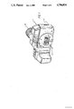
- FIG. 1 is a front perspective view of a compact camera with a built-in electronic flash unit according to a preferred embodiment of the invention
- FIG. 2 is a rear elevation view of the compact camera, showing the flash unit in a folded inoperative position;
- FIG. 3 is a side elevation view of the compact camera, showing the flash unit in its folded inoperative position;
- FIG. 4 is a rear elevation view of the mounting means which supports the flash unit on the compact camera;
- FIG. 5 is a front perspective view of the compact camera, showing the flash unit in an erect operative position
- FIG. 6 is a rear elevation view of the compact camera, showing the flash unit in its erect operative position.
- the invention is described as being embodied in a compact 35 mm camera with a built-in electronic flash unit. Because such photographic cameras have recently become well known, this description is directed in particular to camera elements forming part of or cooperating directly with the preferred embodiment. It is to be understood, however, that camera elements not specifically shown or described may take various forms known to persons of ordinary skill in the art.
- FIGS. 1, 2 and 3 depict the front, rear, and one side of a compact 35 mm camera 1 provided with a built-in electronic flash unit 3.
- the camera body 5 includes a taking lens 7 having a lens axis or optical axis 0, and front and rear aligned viewfinder windows 9 and 11 having a common viewing axis V.
- the viewing axis V as shown inn FIG. 1, extends directly above and substantially parallel to the optical axis 0.
- the flash unit 3 is pivotable with respect to the camera body 5, generally about the rear viewfinder window 11 and in a plane substantially parallel to a rear face 15 of the camera body.
- the pivot axis P of the flash unit 3 extends in coaxial relation with the viewing axis V through the rear viewfinder window 11. See FIGS. 2 and 6.
- the flash unit 3 is pivotable 180° between a folded or inverted inoperative position in which it is located within a recessed area 17 at the rear face 15 of the camera body 5 to form an integrated part of the body, and an erect operative position in which it is removed from the recessed area and is elevated higher than the taking lens 7 and the rear viewfinder window 11.
- the recessed area 17 is bordered by a concave-shaped edge 19 evenly spaced from the pivot axis P, and the flash unit 3 has a convex-shaped edge 21 arranged in contiguous relation with the concave-shaped edge as the flash unit is swung from and to its folded position within the recessed area.
- a flash emission window 23 of the flash unit is located sufficiently higher than the taking lens 5 to substantially prevent red-eye occurrence during a flash exposure.
- the flash unit 3 includes a bore 25 in which an elongate support member 27 for the rear viewfinder window 11 is disposed.
- the bore 25 and the support member 27 are complementary shaped to enable the flash unit 3 to rotate generally about the rear viewfinder window 11.
- the flash unit 3 has a pair of opposite facing semi-hemispherical recesses 29 and 31 which receive respective sprung-urged steel balls 33 and 35, partially located in corresponding pockets 37 and 39 in the support member, to releasably secure the flash unit in its folded or elevated position.
- the flash unit 5 When it is desired to take a flash exposure, the flash unit 5 is pivoted from its folded position shown in FIGS. 2 and 3 to its elevated position shown in FIGS. 5 and 6.
- This arrangement allows for improved compactness in that the flash unit 3 does not have to swing in an arc away from the rear face 15 of the camera body 5 as in prior art U.S. Pat. No. 2,688,071.
- the flash unit 3 since the flash unit 3 is swung generally about the rear viewfinder window 11, rather than about the taking lens 7 as in prior art U.S. Pat. No. 4,666,275, it becomes an easier matter to elevate the flash unit sufficiently higher than the taking lens to substantially prevent red-eye.
Landscapes
- Physics & Mathematics (AREA)
- General Physics & Mathematics (AREA)
- Stroboscope Apparatuses (AREA)
- Structure And Mechanism Of Cameras (AREA)
Abstract
Description
Claims (5)
Priority Applications (5)
| Application Number | Priority Date | Filing Date | Title |
|---|---|---|---|
| US07/168,813 US4796034A (en) | 1988-03-16 | 1988-03-16 | Compact camera with flash unit |
| DE89104507T DE68910560T2 (en) | 1988-03-16 | 1989-03-14 | Compact camera with flash unit. |
| EP89104507A EP0336150B1 (en) | 1988-03-16 | 1989-03-14 | Compact camera with flash unit |
| JP1064912A JPH01304441A (en) | 1988-03-16 | 1989-03-16 | Photoelectric camera |
| HK75394A HK75394A (en) | 1988-03-16 | 1994-07-28 | Compact camera with flash unit |
Applications Claiming Priority (1)
| Application Number | Priority Date | Filing Date | Title |
|---|---|---|---|
| US07/168,813 US4796034A (en) | 1988-03-16 | 1988-03-16 | Compact camera with flash unit |
Publications (1)
| Publication Number | Publication Date |
|---|---|
| US4796034A true US4796034A (en) | 1989-01-03 |
Family
ID=22613037
Family Applications (1)
| Application Number | Title | Priority Date | Filing Date |
|---|---|---|---|
| US07/168,813 Expired - Fee Related US4796034A (en) | 1988-03-16 | 1988-03-16 | Compact camera with flash unit |
Country Status (5)
| Country | Link |
|---|---|
| US (1) | US4796034A (en) |
| EP (1) | EP0336150B1 (en) |
| JP (1) | JPH01304441A (en) |
| DE (1) | DE68910560T2 (en) |
| HK (1) | HK75394A (en) |
Cited By (12)
| Publication number | Priority date | Publication date | Assignee | Title |
|---|---|---|---|---|
| FR2644903A1 (en) * | 1989-03-27 | 1990-09-28 | Asahi Optical Co Ltd | Camera with flash |
| US4980708A (en) * | 1990-01-16 | 1990-12-25 | Eastman Kodak Company | Photographic camera with handgrip |
| US4983999A (en) * | 1990-02-12 | 1991-01-08 | Eastman Kodak Company | Camera with flip-up flash unit |
| US5005032A (en) * | 1990-02-12 | 1991-04-02 | Eastman Kodak Company | Optical finder for camera with flip-up flash unit |
| US5166719A (en) * | 1990-05-28 | 1992-11-24 | Sony Corporation | Eye-cup cover for a viewfinder |
| US5276474A (en) * | 1993-01-19 | 1994-01-04 | Eastman Kodak Company | Compact camera with folding flash unit |
| US5371563A (en) * | 1994-01-13 | 1994-12-06 | Eastman Kodak Company | Electronic flash unit with triggering circuit affixed to reflector |
| US5436686A (en) * | 1994-01-28 | 1995-07-25 | Eastman Kodak Company | Compact camera with cover for handle |
| US5946506A (en) * | 1997-02-07 | 1999-08-31 | Nikon Corporation | Single lens reflex camera with rotatable built-in flash |
| US6304728B1 (en) * | 2000-03-14 | 2001-10-16 | Concord Camera Corp. | Camera with flash unit disposed in between viewfinder lenses |
| US20040100376A1 (en) * | 2002-11-26 | 2004-05-27 | Kimberly-Clark Worldwide, Inc. | Healthcare monitoring system |
| EP2312389A1 (en) * | 2009-10-13 | 2011-04-20 | Dalibor Zyka | A flash unit holder with adjustable position |
Families Citing this family (1)
| Publication number | Priority date | Publication date | Assignee | Title |
|---|---|---|---|---|
| US5337105A (en) * | 1993-01-13 | 1994-08-09 | Eastman Kodak Company | Compact camera with automatically extending flip-up flash unit |
Citations (8)
| Publication number | Priority date | Publication date | Assignee | Title |
|---|---|---|---|---|
| US2688071A (en) * | 1952-05-23 | 1954-08-31 | James A Wright | Flash bulb attachment for cameras |
| US3169708A (en) * | 1961-06-20 | 1965-02-16 | Ferrania Spa | Photographic camera with photoflash unit hinged thereto |
| US4166680A (en) * | 1977-01-27 | 1979-09-04 | Olympus Optical Co., Ltd. | Strobo unit for camera |
| US4319818A (en) * | 1979-07-30 | 1982-03-16 | Fuji Koeki Corporation | Photographic camera |
| US4350420A (en) * | 1979-10-04 | 1982-09-21 | Agfa-Gevaert Aktiengesellschaft | Camera with flash unit |
| GB2106261A (en) * | 1982-06-02 | 1983-04-07 | Hen Long Tseng | Camera having integral flash |
| US4557571A (en) * | 1983-12-16 | 1985-12-10 | Eastman Kodak Company | Compact camera with flash unit |
| US4666275A (en) * | 1984-06-13 | 1987-05-19 | Canon Kabushiki Kaisha | Camera |
Family Cites Families (2)
| Publication number | Priority date | Publication date | Assignee | Title |
|---|---|---|---|---|
| DE2951105A1 (en) * | 1979-12-19 | 1981-06-25 | Agfa-Gevaert Ag, 5090 Leverkusen | Compact camera with extending optics - has swivel hand control incorporating viewfinder |
| JPH05317325A (en) * | 1992-05-19 | 1993-12-03 | Olympus Optical Co Ltd | Guide tube for internal inserting tool |
-
1988
- 1988-03-16 US US07/168,813 patent/US4796034A/en not_active Expired - Fee Related
-
1989
- 1989-03-14 DE DE89104507T patent/DE68910560T2/en not_active Expired - Fee Related
- 1989-03-14 EP EP89104507A patent/EP0336150B1/en not_active Expired - Lifetime
- 1989-03-16 JP JP1064912A patent/JPH01304441A/en active Pending
-
1994
- 1994-07-28 HK HK75394A patent/HK75394A/en unknown
Patent Citations (8)
| Publication number | Priority date | Publication date | Assignee | Title |
|---|---|---|---|---|
| US2688071A (en) * | 1952-05-23 | 1954-08-31 | James A Wright | Flash bulb attachment for cameras |
| US3169708A (en) * | 1961-06-20 | 1965-02-16 | Ferrania Spa | Photographic camera with photoflash unit hinged thereto |
| US4166680A (en) * | 1977-01-27 | 1979-09-04 | Olympus Optical Co., Ltd. | Strobo unit for camera |
| US4319818A (en) * | 1979-07-30 | 1982-03-16 | Fuji Koeki Corporation | Photographic camera |
| US4350420A (en) * | 1979-10-04 | 1982-09-21 | Agfa-Gevaert Aktiengesellschaft | Camera with flash unit |
| GB2106261A (en) * | 1982-06-02 | 1983-04-07 | Hen Long Tseng | Camera having integral flash |
| US4557571A (en) * | 1983-12-16 | 1985-12-10 | Eastman Kodak Company | Compact camera with flash unit |
| US4666275A (en) * | 1984-06-13 | 1987-05-19 | Canon Kabushiki Kaisha | Camera |
Cited By (15)
| Publication number | Priority date | Publication date | Assignee | Title |
|---|---|---|---|---|
| GB2230102B (en) * | 1989-03-27 | 1993-11-24 | Asahi Optical Co Ltd | Camera provided with a strobe |
| GB2230102A (en) * | 1989-03-27 | 1990-10-10 | Asahi Optical Co Ltd | Camera with a strobe on a rotatable arm |
| US5036345A (en) * | 1989-03-27 | 1991-07-30 | Asahi Kogaku Kogyo Kabushiki Kaisha | Camera provided with a strobe |
| FR2644903A1 (en) * | 1989-03-27 | 1990-09-28 | Asahi Optical Co Ltd | Camera with flash |
| US4980708A (en) * | 1990-01-16 | 1990-12-25 | Eastman Kodak Company | Photographic camera with handgrip |
| US4983999A (en) * | 1990-02-12 | 1991-01-08 | Eastman Kodak Company | Camera with flip-up flash unit |
| US5005032A (en) * | 1990-02-12 | 1991-04-02 | Eastman Kodak Company | Optical finder for camera with flip-up flash unit |
| US5166719A (en) * | 1990-05-28 | 1992-11-24 | Sony Corporation | Eye-cup cover for a viewfinder |
| US5276474A (en) * | 1993-01-19 | 1994-01-04 | Eastman Kodak Company | Compact camera with folding flash unit |
| US5371563A (en) * | 1994-01-13 | 1994-12-06 | Eastman Kodak Company | Electronic flash unit with triggering circuit affixed to reflector |
| US5436686A (en) * | 1994-01-28 | 1995-07-25 | Eastman Kodak Company | Compact camera with cover for handle |
| US5946506A (en) * | 1997-02-07 | 1999-08-31 | Nikon Corporation | Single lens reflex camera with rotatable built-in flash |
| US6304728B1 (en) * | 2000-03-14 | 2001-10-16 | Concord Camera Corp. | Camera with flash unit disposed in between viewfinder lenses |
| US20040100376A1 (en) * | 2002-11-26 | 2004-05-27 | Kimberly-Clark Worldwide, Inc. | Healthcare monitoring system |
| EP2312389A1 (en) * | 2009-10-13 | 2011-04-20 | Dalibor Zyka | A flash unit holder with adjustable position |
Also Published As
| Publication number | Publication date |
|---|---|
| DE68910560T2 (en) | 1994-02-24 |
| DE68910560D1 (en) | 1993-12-16 |
| HK75394A (en) | 1994-08-05 |
| EP0336150B1 (en) | 1993-11-10 |
| JPH01304441A (en) | 1989-12-08 |
| EP0336150A1 (en) | 1989-10-11 |
Similar Documents
| Publication | Publication Date | Title |
|---|---|---|
| US4796034A (en) | Compact camera with flash unit | |
| US4557571A (en) | Compact camera with flash unit | |
| US5005032A (en) | Optical finder for camera with flip-up flash unit | |
| US5426478A (en) | Camera with a built-in strobe having a gripping section and a finger intrusion prevention screen | |
| US5276474A (en) | Compact camera with folding flash unit | |
| US4983999A (en) | Camera with flip-up flash unit | |
| US3791274A (en) | Anatomical camera design | |
| US4996548A (en) | Camera with flip-up flash unit | |
| JP3483963B2 (en) | Stereo camera | |
| US4855771A (en) | Compact camera with flash unit movable to reduce red-eye | |
| US5146252A (en) | Pop-out viewfinder for compact camera with flip-up flash unit | |
| JPH04345153A (en) | Photograph camera | |
| US5337105A (en) | Compact camera with automatically extending flip-up flash unit | |
| JPS63201638A (en) | Relay finder for still video back | |
| US4980708A (en) | Photographic camera with handgrip | |
| US5371563A (en) | Electronic flash unit with triggering circuit affixed to reflector | |
| US5708875A (en) | Camera having electronic flash equipment | |
| US5294953A (en) | Camera-to subject distance determining apparatus and method | |
| US4245903A (en) | Photographic camera | |
| EP0557683A1 (en) | Compact camera with integral flash unit | |
| US5319404A (en) | Compact camera with dual-pivot folding flash unit | |
| US5179401A (en) | Photographic camera with wedge-shaped body portion and matching flash | |
| JP4040236B2 (en) | Camera with strobe | |
| JP3094237B2 (en) | Simple camera | |
| GB2306014A (en) | Low-position viewfinder camera |
Legal Events
| Date | Code | Title | Description |
|---|---|---|---|
| FEPP | Fee payment procedure |
Free format text: PAYOR NUMBER ASSIGNED (ORIGINAL EVENT CODE: ASPN); ENTITY STATUS OF PATENT OWNER: LARGE ENTITY |
|
| AS | Assignment |
Owner name: EASTMAN KODAK COMPANY, ROCHESTER, NY A CORP. OF NJ Free format text: ASSIGNMENT OF ASSIGNORS INTEREST.;ASSIGNORS:LEONARD, BRUCE A.;COUCH, JAMES S.;MERVAR, ROBERT W.;REEL/FRAME:004962/0103;SIGNING DATES FROM 19880303 TO 19880311 Owner name: EASTMAN KODAK COMPANY, A CORP. OF NJ, NEW YORK Free format text: ASSIGNMENT OF ASSIGNORS INTEREST;ASSIGNORS:LEONARD, BRUCE A.;COUCH, JAMES S.;MERVAR, ROBERT W.;SIGNING DATES FROM 19880303 TO 19880311;REEL/FRAME:004962/0103 |
|
| FPAY | Fee payment |
Year of fee payment: 4 |
|
| FEPP | Fee payment procedure |
Free format text: PAYER NUMBER DE-ASSIGNED (ORIGINAL EVENT CODE: RMPN); ENTITY STATUS OF PATENT OWNER: LARGE ENTITY Free format text: PAYOR NUMBER ASSIGNED (ORIGINAL EVENT CODE: ASPN); ENTITY STATUS OF PATENT OWNER: LARGE ENTITY |
|
| FPAY | Fee payment |
Year of fee payment: 8 |
|
| REMI | Maintenance fee reminder mailed | ||
| LAPS | Lapse for failure to pay maintenance fees | ||
| FP | Lapsed due to failure to pay maintenance fee |
Effective date: 20010103 |
|
| STCH | Information on status: patent discontinuation |
Free format text: PATENT EXPIRED DUE TO NONPAYMENT OF MAINTENANCE FEES UNDER 37 CFR 1.362 |