US479364A - Machine - Google Patents
Machine Download PDFInfo
- Publication number
- US479364A US479364A US479364DA US479364A US 479364 A US479364 A US 479364A US 479364D A US479364D A US 479364DA US 479364 A US479364 A US 479364A
- Authority
- US
- United States
- Prior art keywords
- stylus
- pattern
- lever
- cutter
- endwise
- Prior art date
- Legal status (The legal status is an assumption and is not a legal conclusion. Google has not performed a legal analysis and makes no representation as to the accuracy of the status listed.)
- Expired - Lifetime
Links
Images


Classifications
-
- B—PERFORMING OPERATIONS; TRANSPORTING
- B23—MACHINE TOOLS; METAL-WORKING NOT OTHERWISE PROVIDED FOR
- B23Q—DETAILS, COMPONENTS, OR ACCESSORIES FOR MACHINE TOOLS, e.g. ARRANGEMENTS FOR COPYING OR CONTROLLING; MACHINE TOOLS IN GENERAL CHARACTERISED BY THE CONSTRUCTION OF PARTICULAR DETAILS OR COMPONENTS; COMBINATIONS OR ASSOCIATIONS OF METAL-WORKING MACHINES, NOT DIRECTED TO A PARTICULAR RESULT
- B23Q35/00—Control systems or devices for copying directly from a pattern or a master model; Devices for use in copying manually
- B23Q35/04—Control systems or devices for copying directly from a pattern or a master model; Devices for use in copying manually using a feeler or the like travelling along the outline of the pattern, model or drawing; Feelers, patterns, or models therefor
- B23Q35/08—Means for transforming movement of the feeler or the like into feed movement of tool or work
- B23Q35/10—Means for transforming movement of the feeler or the like into feed movement of tool or work mechanically only
- B23Q35/101—Means for transforming movement of the feeler or the like into feed movement of tool or work mechanically only with a pattern composed of one or more lines used simultaneously for one tool
- B23Q35/102—Means for transforming movement of the feeler or the like into feed movement of tool or work mechanically only with a pattern composed of one or more lines used simultaneously for one tool of one line
-
- Y—GENERAL TAGGING OF NEW TECHNOLOGICAL DEVELOPMENTS; GENERAL TAGGING OF CROSS-SECTIONAL TECHNOLOGIES SPANNING OVER SEVERAL SECTIONS OF THE IPC; TECHNICAL SUBJECTS COVERED BY FORMER USPC CROSS-REFERENCE ART COLLECTIONS [XRACs] AND DIGESTS
- Y10—TECHNICAL SUBJECTS COVERED BY FORMER USPC
- Y10T—TECHNICAL SUBJECTS COVERED BY FORMER US CLASSIFICATION
- Y10T409/00—Gear cutting, milling, or planing
- Y10T409/30—Milling
- Y10T409/30084—Milling with regulation of operation by templet, card, or other replaceable information supply
- Y10T409/301176—Reproducing means
- Y10T409/302912—Reproducing means including means for operation without manual intervention
Definitions
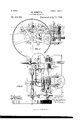
- Figures 1, 2, and 3 are respectively a side elevation, a plan, and an end elevation of a machine of simple form embodying the invention.
- This form of the machine has but a single cutter, and the pattern is arranged upon the periphery of a cylinder.
- Figs. 4, 5, and 6 are respectively a side elevation, a sectional plan, and an end elevation of a more complicated machine embodying the invention.
- This form of the machine has the pattern arranged on a flat plate and may be used with only one cutter or with more than one cutter, as desired.
- the drivingshaft is shown in section on the line 4 4
- Fig. 5 the cutting-plane of Fig. 5 is indicated by the line 5 5, Fig. 4.
- 1 represents the bed-plate of the machine; 2 2, journal-boxes secured to the top side thereof; 3, the driving-shaft journaled in said boxes; 4 4, collars keyed to said shaft and abutting against said boxes for holding the shaft against endwise displacement; 5, the driving-pulley; 6, a cam secured to the shaft between the driving-pulleyand edge of the bed-plate, and 7 a second cam secured to the shaft near its center, the bed-plate being cut away at 8 for its accommodation.
- 9 9 are a second pair of boxes secured to the bed-plate, and 10 a shaft journaled in said boxes, and carrying a pair of worms or endless screws 11 and 12, and a ratchet-wheel 13.
- a lever 15 Fulcrumed upon the outer end of the shaft 10, and confined thereon by a collar 14, is a lever 15, the upper end of which carries a pawl 16 for engaging the teeth of the wheel, while to the lower end is connected one end of a spring 17', which operates to move the lever in one direction.
- the movement in the other direction is produced by the cam 6, acting through the medium of a lever 17, and a rod 18, which connects the upper ends of the two levers, the lower end of lever 17 being fulcrumed to the base of the machine.
- the cam bears upon the lever 17 through the medium of an anti-friction roller 19 and has two equidistant rises or lifts, so that at each halfrevolution of the shaft 3 the pawl 16 is carried forward, and the shaft 10 thereby turned a part revolution.
- 20 is a post rising from the bed-plate, and 21 21 a pair of blocks secured to it by setscrews 22 22,so as to be adjustable vertically thereon. From each of these blocks projects horizontally a stud 23, and to each of these studs is secured, adjustably, a pair of collars 24 24.
- the parts numbered from 20 to 24, inclusive, are duplicated, the corresponding parts being numbered, respectively, 25 to 29, inclusive.
- the parts numbered 20 to 29, inclusive constitute the means for supporting and guiding the strip of wood 30, that is to be carved, and to this end the studs 23 28 and collars 24 29 are so'adjusted that they will bear against the four sides of the strip, as shown most clearly by Fig. 3, and thereby prevent its lateral movement.
- the strip passes between a pair of rollers 31 and 32, and is fed forward by the positive movement of one of them 31, which is roughened and r is driven by the worm 12 through the medium of the worm-wheel 33, while the other 32 is smooth and is idle.
- the upper and lower ends of the shaft of the roller 31 are journaled in blocks 34, (only the upper end of which is shown,) which are mounted to slide in slots formed in plates 35 and 36, the former of which rests upon the bed-plate 1, while the latter is secured to a standard 37 and takes the form of a horizontal arm projecting therefrom.
- the upperand lower ends of the shaft of roller 32 are journaled in blocks 38, the upper one of which is mounted to slide in the slot of the arm 36, while the lower one is mounted to slide in a similar slot formed in an arm 39, projecting from the standard 37 slightly above the plane of the worm-wheel 33.
- the position of the blocks 34 is controlled by set'screws 40, while the blocks 38 are con trolled by set-screws 41, whereby the rollers may be adjusted to the desired positions.
- a stout shaft rising vertically from the bed-plate 1, and fixed thereto by a nut 43.
- a wormwheel 44 which gears with the worm 11, and secured to the hub of said wheel, so as to turn with it, is a cylindrical pattern 45.
- the shaft 42 fits the bore of the pattern snugly, so as to prevent lateral movement, and the pattern is prevented from rising, if necessary, by a plate 46, which engages its upper end, and is secured to the upper end of the shaft by a bolt 47; but ordinarily its own weight will be sufficient to hold it down.
- Fig. 2 shows the standard 37 only in dotted lines (beneath plate 36) and the standard 50 only in section, the cross beam 51 being omitted entirely.
- the arms 53 54 are provided with perforated bosses, through which passes a spindle 59, one end of which carries the cutter 60.
- a spindle 59 Secured to this spindle 59 between the arms 53 and 54 is a pulley 61,0ver whichpasses the belt for giving the cutter the necessary rotary motion, and surrounding it is a coiled spring 62, which bears at one end against the arm 54 and at the other against the pulley 61, whereby the cutter is given a constant tendency to withdraw from its work.
- 63 is 'a lever passing through an opening through the shaft 52, fulcrumed at 64 to the arm 55 and having at one end a stylus 65 for following the pattern.
- the other end 66 of this lever is flattened and fits in a groove cut in a cap 67, which fits on the end of the cutter-spindle 59, the bearing surface of said 1e ver being rounded off, so that notwithstanding the different positions it may assume it will always bear upon the cap directly in theline of the axis of the spindle.
- 69 is an extension of the arm 55, having an opening of just sufficieut size to admit the stylus 65, its ofiice being to receive whatever lateral strain the stylus is subjected to, and thereby relieve the lever 63.
- the arms 53 and 55 and shaft52 constitute in effect and to all intents and purposes a simple lever, the only object in making the shaft 52 so long being to afiord an ample bearing for the spindle 59.
- the arm 54 maybe dispensed with and the parts 52 53 55 reduced to the form of a simple lever, a single bearing of a length adequate to the requirements of the spindle 59 being carried by the arm 53. Therefore where theseparts are heinafter referred to collectively they will be called lever X.
- the relative distances traveled by the out ter and stylus will be proportional to their relative distances from the fulcrum of the lever X, but for a reason that will appear presently the cutter is preferably placed closer to the fulcrum than the stylus is.
- the drawings show them arranged in the relation of one to two, so that the cutter will travel just half the distance traveled by the stylus, but this may be varied.
- the spring 62 holds the stylus constantly in contact with the pattern and causes it to enter all of its depressions, so that as the stylus is moved back and forth over the pattern, as just described, the uneven surface of the pattern, acting through the stylus, will oscillate the lever 63 upon its fulcrum 64.
- the spring 62 is holding the stylus against the bottom of a depression in the pattern and the cutter out of contact with the strip 30.
- the movement of the lever X brings the stylus to an elevated part of the pattern said elevated part will force the stylus outward, and through the medium of the lever 63, &c., force the rapidly-rotating cutter into the strip 30.
- depressions in the pattern cause elevations in the work
- elevations in the pattern cause depressions in the work
- the design must be sunken in the pattern.
- the fulcrum 64 of the lever 63 is equidistant between its point of contact with the spindle 59 and the stylus 65, so that the endwise movements of the cutter and stylus will be coextensive.
- the drawings show an arrangement in which the pattern and the driven feed-roller make the same number of revolutions; but as the feedroller 31 is only half the diameter of the pattern its surface speed (and hence the surface speed of the strip 30) will be only half the surface speed of the pattern, so that the machine, as shown in the drawings, reduces the design of the pattern one-half in all respects excepting the depth of cut, and in this no reduction takes place. Either an increase or a decrease in the depth of cut may be produced by properly proportioning the arms of the lever 63.
- lever X with an additional arm 56, which is similar to the arm 55, but situated on the opposite side of the pattern.
- a lever 73 carrying at its end a stylus 74, which projects through a slotted extension 75, similar to the extension 69.
- This lever is then connected to the lever 63 by a rod or other suitable connection 76, and a spring 77 is also attached to said lever 63 for holding the stylus 74 in contact with the pattern, and the cutter in contact with the stockstrip in opposition to the force of the spring 62, the former spring being stronger than the latter.
- the machine will operate as before, except that the work produced will be a fao simile of the pattern instead of a complement of it.
- the fulcrum 64 of the lever 63 takes the form of a rod extending from the arm 55 to the arm 55 and in order to cause the severallevers 63, 63?, and 63 to move in unison they are all connected toa sleeve 84, that surrounds said rod. Since only one of these levers carries astylus, the stylus ends of the others are omitted, and in order not to interfere with the parallel movement of the levers X and X and their con meeting-rods the lovers 63, &c., are connected to the sleeve 84; by horizontal trunnions 85, 85 and 85".
- the lever 73 is similarly secured to a sleeve 86, from the upper part of which projects an arm 87.
- a similar arm 88 projects from the sleeve 84, and the rod 76 is connectedto these arms instead of directly to the levers 63 and 73, the object being to bring the rod above the pattern.
- This machine may be used with the cylindrical pattern shown by Figs. 1, 2, and 3, or themachine shown by Figs. 1, 2, and 3 may be used with the flat pattern 90. (Shown by Figs. 4, 5, and 6.)
- a flat pattern must of course have arectilinear feed, and to produce this feed is the object of the mechanism now to be described.
- 91 is a slide having beveled or dovetail edges fitting in correspondinggrooves in the adjacent faces of a pair of rails 92, and 93 is a standard rising from said slide and affording a means for attaching the pattern 90.
- a nut 94 Upon the under side of the slide is a nut 94, which fits on a screw 95, suitably supported and held against endwise movement.
- 96 is a miter-wheel secured to the screw
- 97 and 98 are a pair of miter-wheels gearing therewith.
- the wheel 97 is keyed to a shaft 99, to which is also keyed a ratchet-wheel 100, while the wheel 98 is secured to the sleeve 101, surrounding said shaft and carrying a ratchetwheel 102.
- lever 103 is a lever fulcrumed to the shaft 99 and carrying at its upper end a pair of pawls 104 and 105, which are adapted to engage the ratchet-wheels 100 and 102, respectively, said upper end of lever 103 being also connected by a rod 106 with the upper end of lever 15, so that the lever 103 and its pawls partake of all the movements of the lever 15.
- levers 109 and 110 their lower ends are connected by rods 109 and 110, respectively, with the opposite arms of a lever 111, so that when the lever 111 is moved in either direction the levers 107 and 108 will be movedin opposite directions.
- the lever 111 is secured to a shaft 112, having a crank-arm 113, and this arm is connected by a rod 114 with one arm of a bell-crank lever 115, the other arm of which lies in the path of a pair of tappets 116 and 117, carried by the slide 91.
- 118 is a strong plate-spring carrying a V- shaped cam 119
- 120 is a finger carried by the bell-crank lever 115 and engaged by said cam.
- the pawl 104 is in engagement with its ratchet-wheel 100 and the parts are moving in the directions indicated by the arrows.
- the tappet 117 will come in contact with the lever 115 and rock it, overcoming the force of the spring 118.
- the lever 115 will have been moved so far that the finger 120 will have passed the summit of the cam 119.
- the force of the spring 118 will then cause the cam to suddenly shift the position of the lever 115, and thereby draw upon the rod 114, rock the shaft 112, shift the position of the lever 111, reverse the positions of the levers 107 and 108, raise the pawl 104 out of engagement, and allow the pawl 105 to fall into engagement.
- the feed will then be in the opposite direction until the other end of the pattern is reached, whereupon the tappet 116 will in a similar manner cause the parts to be restored to the positions shown in the drawings.
- the design of the pattern is thus successively reproduced in reverse positions on the strips 30.
- the pattern 90 is being followed by the stylus and a complement of it is being produced by the cutter. If a fac-simile is desired, it is secured to the opposite side of the support 93, so that it will be followed by the stylus 74.
- the engraving-machine is intended to make cuts of uniform depth, and consequently no provision is made for transmitting the endwise movements of the stylus to the cutter.
- the pattern is a mere scroll or delineation without varying surface elevations and depressions.
- a carving-machine the combination, with a cutter movable both endwise and laterally, a pattern having elevations and depressions, and a stylus movable both laterally and endwise and adapted to follow the surface of said pattern, of differential connections between said stylus and cutter for transmittiug from the former to the latter both lateral and endwise movement, substantially as set forth.
- the combination with a cutter movable both laterally and endwise, a pattern having elevations and depressions, and a stylus movable both laterally and endwise, of connections between said stylus and cutter, comprising means for transmitting the lateral and endwise movements of the stylus independently of each other, substantially as set forth.
- the combination with acutter movable both laterally and endwise, a pattern having elevations and depressions, and a stylus movable both laterally and endwise for following said pattern, of connections between said stylus and cutter, comprising a pair of differential levers, one transmitting the lateral and the other transmitting the endwise movement of the stylus, substantially as set forth.
- a carving-machine the combination, with acutter movable both laterally and endwise, a pattern having elevations and depressions, and a stylus movable both laterally and endwise, of connections between said stylus and cutter, comprising a lever for transmitting the lateral movement of the stylus and a second lever carried by the first for transmitting the endwise movement of the stylus, substantially as set forth.
- a carving-machine the combination, with a cutter, a pattern, and a stylus for following said pattern, of a lever carrying the stylus and cutter on opposite sides of its fulcrum and a second lever carried by the first and engaging the stylus and cutter-spindle at its opposite ends, said levers having differential motions, substantially as set forth.
- a carving-machine the combination, with a pattern, of means actuated by the pattern, having elevations and depressions for producing a fac-simile thereof, and means actuated by the pattern for producing a complement thereof, both of said means comprising a stylus movable endwise, a cutter movable endwise, and connections between them for transmitting the movement of the former to the latter, substantially as set forth.
Landscapes
- Engineering & Computer Science (AREA)
- Automation & Control Theory (AREA)
- Mechanical Engineering (AREA)
- Control Of Cutting Processes (AREA)
Description
(No Model.) 3 Sheets-She et 1. M HERTEL GARVING MACHINE.
No. 479,364. Patented July 19,1892.
Wat/766566 ms nonms P1751565" rum-manna, WASNINGTON, a c
(No Model.) 3 Sheets-Sheet 2.
M. HERTEL. GARVING MACHINE.
Patented July 19, 1892.
"12 moms PETERB c0, Puma-mum, wnsnma'mu, m c.
(No Model.-) 3 Sheets-Sheet 3.
M. HERTEL.
GARVING MACHINE.
No. 479,364. Patented July 19, 1892.
/" FJabT 23 jm e/zforx ff/dfiy m 1m: ncams PETERS co Pumoumm, msumcrun, n. c
UNITED STATES PATENT FFICE.
MAX HERTEL, OF CHICAGO, ILLINOIS, ASSIGNOR TO THE NATIONAL MACHINE WORKS, OF SAME PLACE.
CARVING-IVIACHINE.
SPECIFICATION forming part of Letters Patent No. 479,364, dated July 19, 1892.
Application filed September 23, 1891. Serial No. 406,564. (No model.)
To all whom it may concern:
Be it known that I, MAX HERTEL, a citizen of the United States, residing at Chicago, in
the county of Cook and State of Illinois, have invented certain new and useful Improvements in Carving-Machines, of which the following is a specification, reference being had to the accompanying drawings, which are made a part hereof, and in Which Figures 1, 2, and 3 are respectively a side elevation, a plan, and an end elevation of a machine of simple form embodying the invention. This form of the machine has but a single cutter, and the pattern is arranged upon the periphery of a cylinder. Figs. 4, 5, and 6 are respectively a side elevation, a sectional plan, and an end elevation of a more complicated machine embodying the invention. This form of the machine has the pattern arranged on a flat plate and may be used with only one cutter or with more than one cutter, as desired. In Fig. 4 the drivingshaft is shown in section on the line 4 4, Fig. 5, and the cutting-plane of Fig. 5 is indicated by the line 5 5, Fig. 4.
The objects of the present invention are fully stated in the descriptive part of this specification, and the features of novelty in which said invention consist are particularly pointed out in the claims hereinafter.
Referring to Figs. 1, 2, and 3 of the drawings, 1 represents the bed-plate of the machine; 2 2, journal-boxes secured to the top side thereof; 3, the driving-shaft journaled in said boxes; 4 4, collars keyed to said shaft and abutting against said boxes for holding the shaft against endwise displacement; 5, the driving-pulley; 6, a cam secured to the shaft between the driving-pulleyand edge of the bed-plate, and 7 a second cam secured to the shaft near its center, the bed-plate being cut away at 8 for its accommodation.
9 9 are a second pair of boxes secured to the bed-plate, and 10 a shaft journaled in said boxes, and carrying a pair of worms or endless screws 11 and 12, and a ratchet-wheel 13.
Fulcrumed upon the outer end of the shaft 10, and confined thereon by a collar 14, is a lever 15, the upper end of which carries a pawl 16 for engaging the teeth of the wheel, while to the lower end is connected one end of a spring 17', which operates to move the lever in one direction. The movement in the other direction is produced by the cam 6, acting through the medium of a lever 17, and a rod 18, which connects the upper ends of the two levers, the lower end of lever 17 being fulcrumed to the base of the machine. The cam bears upon the lever 17 through the medium of an anti-friction roller 19 and has two equidistant rises or lifts, so that at each halfrevolution of the shaft 3 the pawl 16 is carried forward, and the shaft 10 thereby turned a part revolution.
20 is a post rising from the bed-plate, and 21 21 a pair of blocks secured to it by setscrews 22 22,so as to be adjustable vertically thereon. From each of these blocks projects horizontally a stud 23, and to each of these studs is secured, adjustably, a pair of collars 24 24. The parts numbered from 20 to 24, inclusive, are duplicated, the corresponding parts being numbered, respectively, 25 to 29, inclusive. The parts numbered 20 to 29, inclusive, constitute the means for supporting and guiding the strip of wood 30, that is to be carved, and to this end the studs 23 28 and collars 24 29 are so'adjusted that they will bear against the four sides of the strip, as shown most clearly by Fig. 3, and thereby prevent its lateral movement. The strip passes between a pair of rollers 31 and 32, and is fed forward by the positive movement of one of them 31, which is roughened and r is driven by the worm 12 through the medium of the worm-wheel 33, while the other 32 is smooth and is idle. The upper and lower ends of the shaft of the roller 31 are journaled in blocks 34, (only the upper end of which is shown,) which are mounted to slide in slots formed in plates 35 and 36, the former of which rests upon the bed-plate 1, while the latter is secured to a standard 37 and takes the form of a horizontal arm projecting therefrom. The upperand lower ends of the shaft of roller 32 are journaled in blocks 38, the upper one of which is mounted to slide in the slot of the arm 36, while the lower one is mounted to slide in a similar slot formed in an arm 39, projecting from the standard 37 slightly above the plane of the worm-wheel 33. The position of the blocks 34 is controlled by set'screws 40, while the blocks 38 are con trolled by set-screws 41, whereby the rollers may be adjusted to the desired positions.
42 is a stout shaft rising vertically from the bed-plate 1, and fixed thereto by a nut 43. Upon this shaft is loosely mounted a wormwheel 44, which gears with the worm 11, and secured to the hub of said wheel, so as to turn with it, is a cylindrical pattern 45. The shaft 42 fits the bore of the pattern snugly, so as to prevent lateral movement, and the pattern is prevented from rising, if necessary, by a plate 46, which engages its upper end, and is secured to the upper end of the shaft by a bolt 47; but ordinarily its own weight will be sufficient to hold it down.
50 is a standard similar to and opposite the standard 37, and 51 is a cross-beam extending from one to the other, connecting their upper ends. Fig. 2 shows the standard 37 only in dotted lines (beneath plate 36) and the standard 50 only in section, the cross beam 51 being omitted entirely.
52 is a rock-shaft journaled to the standards 37and 50 and having on one side arms 53 and 54 and on the other side arms 55 and 56. This shaft may be journaled in any suitable way, but I prefer to journal it upon the conical points of a pair of bolts 57, that are tapped through the standards and held against turning by jamb-nuts 58.
The arms 53 54 are provided with perforated bosses, through which passes a spindle 59, one end of which carries the cutter 60. Secured to this spindle 59 between the arms 53 and 54 is a pulley 61,0ver whichpasses the belt for giving the cutter the necessary rotary motion, and surrounding it is a coiled spring 62, which bears at one end against the arm 54 and at the other against the pulley 61, whereby the cutter is given a constant tendency to withdraw from its work.
63 is 'a lever passing through an opening through the shaft 52, fulcrumed at 64 to the arm 55 and having at one end a stylus 65 for following the pattern. The other end 66 of this lever is flattened and fits in a groove cut in a cap 67, which fits on the end of the cutter-spindle 59, the bearing surface of said 1e ver being rounded off, so that notwithstanding the different positions it may assume it will always bear upon the cap directly in theline of the axis of the spindle.
69 is an extension of the arm 55, having an opening of just sufficieut size to admit the stylus 65, its ofiice being to receive whatever lateral strain the stylus is subjected to, and thereby relieve the lever 63.
The operation of the parts thus far described is as follows: causes the arm 53 to bear upon the cam 7 through the medium of a roller 71. At diametrically-opposite points the cam 7 has concentric portions, and between these portions the rise and fall are gradual, so that at each complete revolution of the shaft3 the arm 53 is moved steadily, once upward and once A coiled spring 70 downward, and between these two movements there is a period of rest. This, of course, rocks the shaft 52 and causes the cutter 60 and stylus 65 to move in opposite directions, the path traveled by the stylus being indicated by the dotted arcaain Fig. 1. It will be seen that the arms 53 and 55 and shaft52 constitute in effect and to all intents and purposes a simple lever, the only object in making the shaft 52 so long being to afiord an ample bearing for the spindle 59. I desire to have it understood, therefore, that the arm 54 maybe dispensed with and the parts 52 53 55 reduced to the form of a simple lever, a single bearing of a length adequate to the requirements of the spindle 59 being carried by the arm 53. Therefore where theseparts are heinafter referred to collectively they will be called lever X.
The relative distances traveled by the out ter and stylus will be proportional to their relative distances from the fulcrum of the lever X, but for a reason that will appear presently the cutter is preferably placed closer to the fulcrum than the stylus is. The drawings show them arranged in the relation of one to two, so that the cutter will travel just half the distance traveled by the stylus, but this may be varied.
As before explained, the spring 62 holds the stylus constantly in contact with the pattern and causes it to enter all of its depressions, so that as the stylus is moved back and forth over the pattern, as just described, the uneven surface of the pattern, acting through the stylus, will oscillate the lever 63 upon its fulcrum 64. As shown in the drawings, the spring 62 is holding the stylus against the bottom of a depression in the pattern and the cutter out of contact with the strip 30. As soon as the movement of the lever X brings the stylus to an elevated part of the pattern said elevated part will force the stylus outward, and through the medium of the lever 63, &c., force the rapidly-rotating cutter into the strip 30. Hence it will be seen that depressions in the pattern cause elevations in the work, and elevations in the pattern cause depressions in the work, so that if it is desired to produce a raised design on the strip 30 the design must be sunken in the pattern. The fulcrum 64 of the lever 63 is equidistant between its point of contact with the spindle 59 and the stylus 65, so that the endwise movements of the cutter and stylus will be coextensive.
It is found in actual practice that it is not practicable to use a pattern in which the sides and sloping portions of the design are very abrupt, because such abrupt portions will produce severe sidewise strains on the stylus instead of simply moving it endwise. A pattern may be used having rises of, say, forty-five degrees, but a piece of carving in which the sides of the raised portions sloped at any such angle would not be salable, because it would look too flat. It is for this ITO I'Iq
reason that a given lateral movement of the stylus is made to move the cutter a shorter distance than the same endwise movement does. WVith the arrangement shown in the drawings the cutter gets only half the lateral movement of the stylus, but all of its endwise movement, and hence, if the design of the pattern be sunk one-quarter of an inch with rises of forty-five degrees, in the finished work the design will be raised one-quarter of an inch with edges sloping at about sixty-three degrees. I do not limit myself to the precise arrangement shown in the drawings for accomplishing this result. It may be accomplished by making the arms 53 and 55 of the lever X of equal length and the arms of the lever 63 of unequal length, the essential feature being that the means connecting the stylus and cutter shall impart to the latterthe differential movement described. As soon as the lever X completes its movement in either direction the roller 71 arrives at one or the other of the concentric portions of the cam 7, and the lever is thereby held at rest.
During this interval of rest one of the rises of the cam 6 comes in contact with the lever 17 and by the devices already described advances the pawl 16, and thereby turns the shaft 10. The worm 11, acting through the means of the worm-wheel 44, turns the pattern a short distance, and the worm 12, actingin asimilar manner through the worm-wheel 33, turns the feed-roller 31. In this way the pattern and stock-strip are fed forward simultaneously. Whether the stock-strip should be fed forward at the same surface speed as the pattern or not depends upon circumstances. Ordinarily the surface movement of the strip should be to the surface movement of the pattern as the lateral movement of the cutter is to the lateral movementof the stylus; but there are instances in which it would not be absolutely necessary to maintain these relations. The drawings show an arrangement in which the pattern and the driven feed-roller make the same number of revolutions; but as the feedroller 31 is only half the diameter of the pattern its surface speed (and hence the surface speed of the strip 30) will be only half the surface speed of the pattern, so that the machine, as shown in the drawings, reduces the design of the pattern one-half in all respects excepting the depth of cut, and in this no reduction takes place. Either an increase or a decrease in the depth of cut may be produced by properly proportioning the arms of the lever 63.
As before stated the arrangement thus far described does not produce a fac-simile of the pattern. It produces only a complement of it. Very often this is all sufficient, as it just as .easy to make a pattern with a sunken as.
with a raised design and often easier; but sometimes it is desirable to produce both a fac-simile and a complement of the pattern. To this end I provide the lever X with an additional arm 56, which is similar to the arm 55, but situated on the opposite side of the pattern. To this arm is fulcrumed at 72 a lever 73, carrying at its end a stylus 74, which projects through a slotted extension 75, similar to the extension 69. This lever is then connected to the lever 63 by a rod or other suitable connection 76, and a spring 77 is also attached to said lever 63 for holding the stylus 74 in contact with the pattern, and the cutter in contact with the stockstrip in opposition to the force of the spring 62, the former spring being stronger than the latter. The stylus being then retracted or removed, the machine will operate as before, except that the work produced will be a fao simile of the pattern instead of a complement of it. A fac-simile and a complement of a given pattern, the former made by using the stylus 74 and thelatter by using the stylus 65,
will be complementary to each other-that is to say, if placed face to face the raised portions of the one will fill sunken portions of the other. Hence if all the depressions are of equal depth the two may be glued together, face to face, and if they are wood of different colors one may be planed away until the carvingis reached, and the design wroughtin wood of one color will be found inlaid in the wood of the other color.
The machine shown in Figs. 4:, 5, and 6 differs from the one already'described only in so far as the use of a number of cutters and a flat pattern render a different construction necessary, the principle involved in both be- Above the lever X is a similar lever X, and
similar parts of the two are indicated by similar reference-numerals with the letter added to distinguish the parts of the lever X. The ends of the arms 53 and 53, 54 and 5st, 55 and 55*,156 and 56 are so connected together by vertical rods 8O, 81, 82, and 83, respectively, that the parts are capable of a parallel motion. The styluses 65 and 7 t are carried by the rods 82 and 83, respectively, while the rods 80 and 81 afford the means for supporting any desired number of cutter-spindles, three (59, 59, and 59 being shown by the drawings. The fulcrum 64 of the lever 63 takes the form of a rod extending from the arm 55 to the arm 55 and in order to cause the severallevers 63, 63?, and 63 to move in unison they are all connected toa sleeve 84, that surrounds said rod. Since only one of these levers carries astylus, the stylus ends of the others are omitted, and in order not to interfere with the parallel movement of the levers X and X and their con meeting-rods the lovers 63, &c., are connected to the sleeve 84; by horizontal trunnions 85, 85 and 85". The lever 73 is similarly secured to a sleeve 86, from the upper part of which projects an arm 87. A similar arm 88 projects from the sleeve 84, and the rod 76 is connectedto these arms instead of directly to the levers 63 and 73, the object being to bring the rod above the pattern. This machine may be used with the cylindrical pattern shown by Figs. 1, 2, and 3, or themachine shown by Figs. 1, 2, and 3 may be used with the flat pattern 90. (Shown by Figs. 4, 5, and 6.) A flat pattern must of course have arectilinear feed, and to produce this feed is the object of the mechanism now to be described.
91 is a slide having beveled or dovetail edges fitting in correspondinggrooves in the adjacent faces of a pair of rails 92, and 93 is a standard rising from said slide and affording a means for attaching the pattern 90. Upon the under side of the slide is a nut 94, which fits on a screw 95, suitably supported and held against endwise movement. 96 is a miter-wheel secured to the screw, and 97 and 98 are a pair of miter-wheels gearing therewith. The wheel 97 is keyed to a shaft 99, to which is also keyed a ratchet-wheel 100, while the wheel 98 is secured to the sleeve 101, surrounding said shaft and carrying a ratchetwheel 102.
103 is a lever fulcrumed to the shaft 99 and carrying at its upper end a pair of pawls 104 and 105, which are adapted to engage the ratchet- wheels 100 and 102, respectively, said upper end of lever 103 being also connected by a rod 106 with the upper end of lever 15, so that the lever 103 and its pawls partake of all the movements of the lever 15. It will now be seen that in order to turn the shaft 99, and thereby impart a motion to the slide 91 in one direction, it is simply necessary to hold the pawl 105 out of engagement with the ratchet-wheel 102, and in order to turn the sleeve 101, and thereby impart motion to the said slide in the opposite direction, it is only necessary to hold the pawl 104 out of contact.
with the ratchet-wheel 100. To this end a pair of trip- levers 107 and 108 are fulcrumed to the shaft 99 between the ratchet-wheels with their upper ends in the paths of the pawls 104 and 105, respectively. These levers are long enough to project beyond the teeth of the ratchet-wheels, so that when either is moved toward its pawl it engages its under side and lifts and holds it out of engagement.
To operate these levers so that one will bein' and the other out of engagement with its pawl, their lower ends are connected by rods 109 and 110, respectively, with the opposite arms of a lever 111, so that when the lever 111 is moved in either direction the levers 107 and 108 will be movedin opposite directions. The lever 111 is secured to a shaft 112, having a crank-arm 113, and this arm is connected by a rod 114 with one arm of a bell-crank lever 115, the other arm of which lies in the path of a pair of tappets 116 and 117, carried by the slide 91.
118 is a strong plate-spring carrying a V- shaped cam 119, and 120 is a finger carried by the bell-crank lever 115 and engaged by said cam.
As shown in the drawings, the pawl 104 is in engagement with its ratchet-wheel 100 and the parts are moving in the directions indicated by the arrows. Just before the pattern completes its motion in the direction indicated the tappet 117 will come in contact with the lever 115 and rock it, overcoming the force of the spring 118. When the pattern has quite completed its movement, the lever 115 will have been moved so far that the finger 120 will have passed the summit of the cam 119. The force of the spring 118 will then cause the cam to suddenly shift the position of the lever 115, and thereby draw upon the rod 114, rock the shaft 112, shift the position of the lever 111, reverse the positions of the levers 107 and 108, raise the pawl 104 out of engagement, and allow the pawl 105 to fall into engagement. The feed will then be in the opposite direction until the other end of the pattern is reached, whereupon the tappet 116 will in a similar manner cause the parts to be restored to the positions shown in the drawings. The design of the pattern is thus successively reproduced in reverse positions on the strips 30. As shown in the drawings, the pattern 90 is being followed by the stylus and a complement of it is being produced by the cutter. If a fac-simile is desired, it is secured to the opposite side of the support 93, so that it will be followed by the stylus 74.
I am aware that in engraving-machines the stylus and cutter have been so connected that the latter will partake of all of the lateral movements of the former, and I do not claim mechanism for producing this result in a carving-machine. The engraving-machine is intended to make cuts of uniform depth, and consequently no provision is made for transmitting the endwise movements of the stylus to the cutter. The pattern is a mere scroll or delineation without varying surface elevations and depressions.
What I claim as new, and desire to secure by Letters Patent, is-
1. In a carving-machine, the combination, with a cutter movable both endwise and laterally, a pattern having elevations and depressions, and a stylus movable both laterally and endwise and adapted to follow the surface of said pattern, of differential connections between said stylus and cutter for transmittiug from the former to the latter both lateral and endwise movement, substantially as set forth.
2. In a carving-machine, the combination, with a cutter movable both laterally and endwise, a pattern having elevations and depressions, and a stylus movable both laterally and endwise, of connections between said stylus and cutter, comprising means for transmitting the lateral and endwise movements of the stylus independently of each other, substantially as set forth.
3. In a carving-machine, the combination, with acutter movable both laterally and endwise, a pattern having elevations and depressions, and a stylus movable both laterally and endwise for following said pattern, of connections between said stylus and cutter, comprising a pair of differential levers, one transmitting the lateral and the other transmitting the endwise movement of the stylus, substantially as set forth. 1
4:. In a carving-machine, the combination, with acutter movable both laterally and endwise, a pattern having elevations and depressions, and a stylus movable both laterally and endwise, of connections between said stylus and cutter, comprising a lever for transmitting the lateral movement of the stylus and a second lever carried by the first for transmitting the endwise movement of the stylus, substantially as set forth.
5. In a carving-machine, the combination, with a cutter, a pattern, and a stylus for following said pattern, of a lever carrying the stylus and cutter on opposite sides of its fulcrum and a second lever carried by the first and engaging the stylus and cutter-spindle at its opposite ends, said levers having differential motions, substantially as set forth.
6. In a carving-machine, the combination, with a cutter, a pattern, and a stylus, of alever carrying the cutter and stylus at different distances from its fulcrum and a second lever fulcrumed to the first and engaging the cutter-shaft and stylus at equal distances from its fulcrum, substantially as set forth.
7. In a carving-machine, the combination of the lever X, having arms 53 and 55, the cutter 60, the endwise-movable spindle 62, carried by the arm 53, the endwise-movable stylus 65, engaged by the arm 55, and the lever 63, fulcrumed to the lever X and engaging the spindle 62 and stylus 65, substantially as Set forth.
8. In a carving-machine, the combination of the lever X, having arms 53, 54, and 55, the endwise-movable cutter-spindle 62, j ournaled in the arms 53 and 54, the pulley 61, and the spindle, the spring 65, surrounding and eX- erting its force against the spindle, the endwise-movable stylus 65, engaged by the arm 55, and the lever 63, fulcrumed to the lever X andengaging the cutter-spindle and stylus, substantially as set forth.
9. In a carving-machine, the combination, with a pattern, of means actuated by the pattern, having elevations and depressions for producing a fac-simile thereof, and means actuated by the pattern for producing a complement thereof, both of said means comprising a stylus movable endwise, a cutter movable endwise, and connections between them for transmitting the movement of the former to the latter, substantially as set forth.
10. In a carving-machine, the combination, with a cutter and pattern, of two styluses presented in opposite directions and adapted to engage the pattern from opposite sides and means for transmitting the movement of either stylus to the cutter, substantially as set forth.
11. The combination,with the endwise-movable cutter and the pattern, of a pair of styluses, a pair of levers partaking of the endwise movement of said styluses, and means for transmitting the movement of either of said levers to the cutter, substantially as set forth.
12. The combination,with the endwise-movable cutter'and the pattern,of the stylus 65,the lever 63, partaking of the endwise movement of said stylus and transmitting it to the cutter, the second stylus 7 4E, thelever 73, by which it is carried, and a connection between the levers 63 and 73, substantially as set forth.
13. In a carving-machine, the combination of the levers X and X*, the bar 80, connecting them, a plurality of cutters having spindles journaledin said bars, means for oscillating the levers, and means for producing the desired endwise movement of the cutterspindles, substantially as set forth.
14:. The combination of the levers X and X, the bars and 82, connecting them, a plurality of cutters having their spindles journaled in bar 80, the rod 64, connected to levers X and X the sleeve 84, surrounding said rod, a plurality of levers 63, &c., fulcrumed to the sleeve and engaging the cutterspindles, the stylus 65, engaged by the lever 63 and rod 82, and a pattern, substantially as set forth.
15. In a carving-machine, the combination, with a cutter movable endwise and means for feedingthe stock, of an oscillating lever carrying the cutter back and forth across the stock and means for producing the desired endwise movement of the cutter, substantially as set forth.
16., In a carving-machine, the combination, with a cutter movable endwise, a stylus movable endwise, and a pattern having elevations and depressions, of means for simultaneously advancing the pattern and stock at different surface speeds, an oscillating lever carrying the stylus and cutter, and means for transmitting the endwise movement of the stylus to the cutter, substantially as set forth.-
MAX HERTEL.
Witnesses L. M. HOPKINS, J. HALPENNY.
Publications (1)
| Publication Number | Publication Date |
|---|---|
| US479364A true US479364A (en) | 1892-07-19 |
Family
ID=2548218
Family Applications (1)
| Application Number | Title | Priority Date | Filing Date |
|---|---|---|---|
| US479364D Expired - Lifetime US479364A (en) | Machine |
Country Status (1)
| Country | Link |
|---|---|
| US (1) | US479364A (en) |
Cited By (1)
| Publication number | Priority date | Publication date | Assignee | Title |
|---|---|---|---|---|
| US2706426A (en) * | 1948-09-14 | 1955-04-19 | Kelley Ind Inc | Apparatus for repeatedly reproducing three-dimensional designs |
-
0
- US US479364D patent/US479364A/en not_active Expired - Lifetime
Cited By (1)
| Publication number | Priority date | Publication date | Assignee | Title |
|---|---|---|---|---|
| US2706426A (en) * | 1948-09-14 | 1955-04-19 | Kelley Ind Inc | Apparatus for repeatedly reproducing three-dimensional designs |
Similar Documents
| Publication | Publication Date | Title |
|---|---|---|
| US946989A (en) | Lathe. | |
| US1010657A (en) | Drilling-machine. | |
| US1516186A (en) | Slotting machine | |
| US570070A (en) | stowell | |
| US1106177A (en) | Peeling-machine for wood logs. | |
| US679278A (en) | Metal-working machine. | |
| US560574A (en) | delin | |
| US35894A (en) | Improvement in machines for dressing millstones | |
| US560871A (en) | Attachment for stone-planing machines | |
| US274886A (en) | Shire | |
| US469047A (en) | Machine foe engeaving in eelievo | |
| US504812A (en) | Polygonal lathe | |
| US658277A (en) | Radial planing-machine. | |
| US1744857A (en) | Milling machine | |
| US525613A (en) | Machine | |
| US342357A (en) | Machine for cutting elliptical | |
| US474995A (en) | Lathe for turning wagon-axles | |
| US1213237A (en) | Drop-table mechanism for milling-machines. | |
| US842697A (en) | Machine for engraving and die-sinking. | |
| US520581A (en) | stuart | |
| US735338A (en) | File-cutting machine. | |
| US422912A (en) | Wood-channeling machine | |
| US1004345A (en) | Attachment for veneer-cutting machines. | |
| US164381A (en) | Improvement in machines for cutting siding | |
| US397151A (en) | Rolls for flaming-machines |