US4789176A - Adjustable cycle-type seat post assembly - Google Patents
Adjustable cycle-type seat post assembly Download PDFInfo
- Publication number
- US4789176A US4789176A US07/129,234 US12923487A US4789176A US 4789176 A US4789176 A US 4789176A US 12923487 A US12923487 A US 12923487A US 4789176 A US4789176 A US 4789176A
- Authority
- US
- United States
- Prior art keywords
- seat post
- seat
- mounting shaft
- mast
- cylindrical bore
- Prior art date
- Legal status (The legal status is an assumption and is not a legal conclusion. Google has not performed a legal analysis and makes no representation as to the accuracy of the status listed.)
- Expired - Fee Related
Links
Images
Classifications
-
- B—PERFORMING OPERATIONS; TRANSPORTING
- B62—LAND VEHICLES FOR TRAVELLING OTHERWISE THAN ON RAILS
- B62K—CYCLES; CYCLE FRAMES; CYCLE STEERING DEVICES; RIDER-OPERATED TERMINAL CONTROLS SPECIALLY ADAPTED FOR CYCLES; CYCLE AXLE SUSPENSIONS; CYCLE SIDE-CARS, FORECARS, OR THE LIKE
- B62K19/00—Cycle frames
- B62K19/30—Frame parts shaped to receive other cycle parts or accessories
- B62K19/36—Frame parts shaped to receive other cycle parts or accessories for attaching saddle pillars, e.g. adjustable during ride
-
- B—PERFORMING OPERATIONS; TRANSPORTING
- B62—LAND VEHICLES FOR TRAVELLING OTHERWISE THAN ON RAILS
- B62J—CYCLE SADDLES OR SEATS; AUXILIARY DEVICES OR ACCESSORIES SPECIALLY ADAPTED TO CYCLES AND NOT OTHERWISE PROVIDED FOR, e.g. ARTICLE CARRIERS OR CYCLE PROTECTORS
- B62J1/00—Saddles or other seats for cycles; Arrangement thereof; Component parts
- B62J1/08—Frames for saddles; Connections between saddle frames and seat pillars; Seat pillars
Definitions
- This invention relates generally to a saddle for a bicycle, or a stationary cycle-type exerciser, or the like, that can be quickly and easily adjusted to various heights while it is in use.
- the optimum height for a bicycle saddle is different when the bicycle is at rest and when it is in use.
- the saddle should be low enough for his or her feet to touch the ground.
- the saddle should be raised to a desired level so the rider can apply an effective force on the pedals in the most comfortable position. This is especially important to minimize fatigue on long rides. Further, from the standpoint of both comfort and safety, it is an advantage to raise the saddle to one height for climbing a hill and to lower it for descending. The raised and lowered positions will be specifically different for different persons.
- the primary purpose of the present invention is to provide an adjustable bicycle-type seat post assembly with which the rider can quickly and easily adjust the height of the saddle while mounted thereon.
- Another purpose is to provide an adjustable seat post assembly which can be retrofitted into the tubular seat mast of most bicycle, tricycle, and cycle exerciser frames without altering the frame construction with special bolts, clamps, outside springs, or drilled holes.
- Another purpose is to provide an adjustable seat post assembly which can be substituted for a standard, non-adjustable seat post, without making any structural changes in the tubular seat mast.
- Another object is to provide such a completely self-contained adjustable seat post assembly including a tubular seat post with a mounting shaft telescopically slidable therein and piston and cylinder means defining a variable volume air chamber, valve means to pressurize the air chamber and urge the seat post upwardly, at least one opening in the mounting shaft engaging a water bottle stud extending through the seat mast wall, and a quick release clamp at the top of the seat mast.
- Another object is to provide such a completely self-contained adjustable seat post assembly having blind guide ribs flanking the opening in the mounting shaft to facilitate blind assembly within the tubular seat mast.
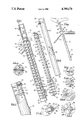
- FIG. 1 is a fragmentary side elevational view of a bicycle using an adjustable seat post assembly according to the present invention
- FIG. 2 is an enlarged side view of a seat post comprising one component of the seat post assembly
- FIG. 3 is an enlarged side view of a mounting shaft comprising another component of the seat post assembly
- FIGS. 4, 5, 6, and 7 are transverses, enlarged cross-sectional views of FIG. 3 taken on lines 4--4, 5--5, 6--6, and 7--7 respectively;
- FIG. 8 is a fragmentary, enlarged view of FIG. 1 without the saddle and with portions cut away and other portions sectioned, to show the seat post assembly secured in working position;
- FIG. 9 is a cross-sectional view of FIG. 8, taken on line 9--9;
- FIG. 10 is a bottom view of the assembly taken on line 10--10 of FIG. 8;
- FIG. 11 is a fragmentary, enlarged, partially sectioned view of FIG. 8.
- an adjustable seat post assembly illustrating a preferred embodiment of the invention is generally designated 20. As shown in FIGS. 1 and 8, it is telescopically slidably assembled, and operable within a tubular seat mast 22 having a frame top tube 24 and seatstay tubes 26. These frame tubes are joined, typically by welding or brazing, to a lug fitment 28 incorporating a quick-release clamp 30. The lug fitment is split on the backside as shown at 32. Turning clamp handle 34 in one direction tightens the seat post binder bolt 36 to grip the seat post and hold it in a selected elevated position. Turning the handle in the opposite direction loosens the clamp to enable resetting the saddle height. A saddle 38 is mounted at the top of the seat post. The saddle mounting and the quick-release clamp may be conventional and form no part of the present invention, so they are not shown in detail.
- the adjustable seat post assembly 20 comprises a tubular seat post 40 and a mounting shaft 42.
- the seat post 40 comprises a round cross-section tube 44 preferably of metal such as aluminum or steel with an outside surface sized to fit for up and down slidable movement within the tubular seat mast 22, and having an inside, polished cylindrical bore 46 with a closed upper end 48 and a lower open end 50.
- a bicycle-type air valve 52 commonly known as a "Schraeder" valve, is connected to the upper end of the seat post and is threadedly engaged with a reinforcing lug 54 secured to the inner wall.
- the mounting shaft 42 is preferably injection-molded in a single piece from a durable plastics material such as a carbon-fiber-reinforced polycarbonate or nylon compound. It has an elongated body with an upper head portion 62, an intermediate portion 64, and a lower head portion 66.
- the upper head portion 62 is a piston 62 is a piston having a pair of grooves 68 with O-rings 70 providing an air seal against the polished cylindrical bore 46.
- a variable volume air chamber 72 is thus provided between the piston and the closed upper end.
- Bicycle valve 52 has external threads engageable with the outlet fitting of a conventional bicycle pump (not shown) for pressurizing the air chamber.
- the intermediate portion 64 of the mounting shaft is formed with a pair of diametrically opposite, longitudinally extending ribs 74,74 (FIGS. 3 and 5), a plurality of pairs of semi-circular ribs 76,76 (FIGS. 3, 5, and 8), and a longitudinall-extending through-slot 78 (FIGS. 3, 4, 5, and 9).
- the slot 78 engages a pin 80 which extends diametrically across the seat post tube 44. This pin and slot connection limits outward movement of the seat post tube 44 under air pressure in chamber 72, and prevents torsional movement of the seat post tube relative to the mounting shaft 42.
- the lower head portion 66 has aperture means engageable with a securing member carried by the seat mast to anchor the seat post assembly within it.
- a securing member carried by the seat mast to anchor the seat post assembly within it.
- the suds or screws 84 which engage these nuts and which extend into the seat mast provide excellent components for removeably anchoring the seat post assembly. If a seat mast does not happen to have a water bottle retaining nut, it is easy for any bicycle mechanic to install one, making this invention suitable for retrofitting in existing bicycles, tricycles, and cycle exercisers.
- the aperture means is here illustrated as a plurality of openings 86 in the lower head portion. These are spaced apart along the length of the mounting shaft as best shown in FIG. 3.
- a circularly-extending rib 88 is provided in coplanar relationship with each opening 86. Further, each opening 86 terminates at a flat surface 90 which is recessed behind the rib ends 92,92 an amount "x" as best shown in FIGS. 7 and 10. This greatly facilitates assembly which is carried out efficiently by inserting the seat post assembly with the lower head portion 66 leading and initially oriented so the openings 86 face generally forwardly toward the nuts 82.
- the securing screw 84 will be only partially engaged with the nut 82 and will extend just slightly beyond the nut inside the seat mast tube 22 as shown in broken lines in FIG. 10.
- the seat post assembly can be rotated tentatively one direction or the other to find the space 96 (FIGS. 6 and 7) between the rib ends 92,92. The mechanic will then know the screw is vertically aligned with the openings 86 and can readily insert the assembly to the desired depth and tighten the screw 84 into the nearest opening 86.
- This adjustment can be made quickly while the bicycle, tricycle, or cycle exerciser is being ridden. For example, in starting to climb a steep grade, the rider may release the clamp, relieve the weight on the saddle to let is rise, and then clamp it in an elevated position. On reaching the top of the grade, the rider will reverse the adjustment and ride down hill with the saddle in a lowered position.
Landscapes
- Engineering & Computer Science (AREA)
- Mechanical Engineering (AREA)
- Motorcycle And Bicycle Frame (AREA)
Abstract
Description
Claims (14)
Priority Applications (1)
| Application Number | Priority Date | Filing Date | Title |
|---|---|---|---|
| US07/129,234 US4789176A (en) | 1987-12-07 | 1987-12-07 | Adjustable cycle-type seat post assembly |
Applications Claiming Priority (1)
| Application Number | Priority Date | Filing Date | Title |
|---|---|---|---|
| US07/129,234 US4789176A (en) | 1987-12-07 | 1987-12-07 | Adjustable cycle-type seat post assembly |
Publications (1)
| Publication Number | Publication Date |
|---|---|
| US4789176A true US4789176A (en) | 1988-12-06 |
Family
ID=22439014
Family Applications (1)
| Application Number | Title | Priority Date | Filing Date |
|---|---|---|---|
| US07/129,234 Expired - Fee Related US4789176A (en) | 1987-12-07 | 1987-12-07 | Adjustable cycle-type seat post assembly |
Country Status (1)
| Country | Link |
|---|---|
| US (1) | US4789176A (en) |
Cited By (22)
| Publication number | Priority date | Publication date | Assignee | Title |
|---|---|---|---|---|
| US5618052A (en) * | 1995-06-15 | 1997-04-08 | Rendall; Barry A. | Bicycle attachment |
| US5695241A (en) * | 1995-09-08 | 1997-12-09 | Olsen; Douglas G. | Adjustable seat post clamp assembly for human-powered vehicles |
| US5979978A (en) * | 1995-09-08 | 1999-11-09 | Advanced Composites, Inc. | Adjustable seat post clamp assembly for human-powered vehicles |
| US6220581B1 (en) * | 1995-10-06 | 2001-04-24 | Thomas L. Mueller | Bicycle seat gas spring adjustment system |
| US6561400B2 (en) | 1999-12-13 | 2003-05-13 | Michael Lee | Mounting assembly for motor vehicles |
| US6581919B2 (en) | 2001-08-20 | 2003-06-24 | Eko Sport, Inc. | Shock absorbing seat post |
| US20050012365A1 (en) * | 2003-07-14 | 2005-01-20 | Douglas Chiang | Bicycle seat post |
| US20050275254A1 (en) * | 2004-06-14 | 2005-12-15 | Ty Anderson | Bicycle seat adapter |
| US20080038161A1 (en) * | 2006-08-09 | 2008-02-14 | Marti Michael A | Method For Producing A Catalyst And The Catalyst Made Therefrom |
| US20080127770A1 (en) * | 2006-12-01 | 2008-06-05 | Angelo Morelli | Height Adjustment Device For Saddles Or Handlebars |
| US20090324327A1 (en) * | 2008-06-30 | 2009-12-31 | Specialized Bicycle Components, Inc. | Vertically adjustable bicycle assembly |
| EP1958760A3 (en) * | 2007-02-17 | 2010-02-17 | Trek Bicycle Corporation | Composite bicycle frame with bottom bracket assembly, fork and seat attachment |
| US20100320814A1 (en) * | 2007-12-04 | 2010-12-23 | Rolf Singenberger | Support and holding device for bicycle saddle |
| US20110187166A1 (en) * | 2010-02-03 | 2011-08-04 | Walsh Austin A | Bicycle Seat Height Adjusting Assembly |
| US20120104810A1 (en) * | 2010-11-03 | 2012-05-03 | Walsh Austin A | Bicycle Seat Height Adjusting Assembly |
| US8888115B2 (en) | 2010-04-07 | 2014-11-18 | Specialized Bicycle Components, Inc. | Bicycle seat tube |
| US8926216B2 (en) | 2011-03-11 | 2015-01-06 | Specialized Bicycle Components, Inc. | Adjustable assembly for a bicycle |
| US10246155B2 (en) | 2011-03-11 | 2019-04-02 | Specialized Bicycle Components, Inc. | Adjustable assembly for a bicycle |
| US11351815B2 (en) | 2017-08-21 | 2022-06-07 | The Hive Global, Inc. | Bicycle cassette with clamping connection |
| US11485449B2 (en) | 2015-09-01 | 2022-11-01 | The Hive Global, Inc. | Bicycle cassette with locking connection |
| TWI794653B (en) * | 2019-09-27 | 2023-03-01 | 勁鋒鐵馬股份有限公司 | Telescopic bicycle seatpost with adjustable uncompressed resting height |
| US11932351B2 (en) | 2020-07-17 | 2024-03-19 | The Hive Global, Inc. | Conical bicycle cassette sprocket structure |
Citations (13)
| Publication number | Priority date | Publication date | Assignee | Title |
|---|---|---|---|---|
| US598234A (en) * | 1898-02-01 | Bicycle | ||
| US622179A (en) * | 1899-03-28 | Pneumatic-cushion seat-post | ||
| GB189914225A (en) * | 1899-07-10 | 1899-08-12 | John Robert Robson | Improvements in and in connection with Saddle Pillars for Cycles or like Vehicles. |
| CH17787A (en) * | 1898-10-13 | 1899-08-31 | Georg Schmidt | Spring-loaded handlebars on bicycles |
| US2623573A (en) * | 1951-05-26 | 1952-12-30 | Gaetano Salvatore J Di | Spring seat post for bicycles |
| US2644504A (en) * | 1950-05-23 | 1953-07-07 | Vick Millard | Bicycle seat height adjusting means |
| US3861740A (en) * | 1973-06-18 | 1975-01-21 | Showa Mfg | Saddle position adjusting device for a vehicle such as bicycle |
| US3891270A (en) * | 1974-05-10 | 1975-06-24 | Krueger Metal Products | Pneumatic stool with foot rest connected to seat base |
| FR2399353A1 (en) * | 1977-08-02 | 1979-03-02 | Shimano Industrial Co | Bicycle saddle vertical adjustment mechanism - has lever-operated thruster acting on slide bearing against upright sliding in tube |
| US4150851A (en) * | 1977-09-07 | 1979-04-24 | Henry Cienfuegos | Seat for bicycles and the like |
| FR2441110A1 (en) * | 1978-11-13 | 1980-06-06 | Simplex Ets | Adjustable saddle mounting for bicycle - uses tube sliding into split frame socket for clamping and also includes sealing ring |
| DE2900780A1 (en) * | 1979-01-10 | 1980-07-24 | Joseph Doblhoff | Folding bicycle with telescopic air spring - has spring supporting saddle and handlebar with valve to connect spaces on either side of spring piston |
| US4580835A (en) * | 1984-04-02 | 1986-04-08 | Angell Joshua J | Quick adjusting saddle locator |
-
1987
- 1987-12-07 US US07/129,234 patent/US4789176A/en not_active Expired - Fee Related
Patent Citations (13)
| Publication number | Priority date | Publication date | Assignee | Title |
|---|---|---|---|---|
| US598234A (en) * | 1898-02-01 | Bicycle | ||
| US622179A (en) * | 1899-03-28 | Pneumatic-cushion seat-post | ||
| CH17787A (en) * | 1898-10-13 | 1899-08-31 | Georg Schmidt | Spring-loaded handlebars on bicycles |
| GB189914225A (en) * | 1899-07-10 | 1899-08-12 | John Robert Robson | Improvements in and in connection with Saddle Pillars for Cycles or like Vehicles. |
| US2644504A (en) * | 1950-05-23 | 1953-07-07 | Vick Millard | Bicycle seat height adjusting means |
| US2623573A (en) * | 1951-05-26 | 1952-12-30 | Gaetano Salvatore J Di | Spring seat post for bicycles |
| US3861740A (en) * | 1973-06-18 | 1975-01-21 | Showa Mfg | Saddle position adjusting device for a vehicle such as bicycle |
| US3891270A (en) * | 1974-05-10 | 1975-06-24 | Krueger Metal Products | Pneumatic stool with foot rest connected to seat base |
| FR2399353A1 (en) * | 1977-08-02 | 1979-03-02 | Shimano Industrial Co | Bicycle saddle vertical adjustment mechanism - has lever-operated thruster acting on slide bearing against upright sliding in tube |
| US4150851A (en) * | 1977-09-07 | 1979-04-24 | Henry Cienfuegos | Seat for bicycles and the like |
| FR2441110A1 (en) * | 1978-11-13 | 1980-06-06 | Simplex Ets | Adjustable saddle mounting for bicycle - uses tube sliding into split frame socket for clamping and also includes sealing ring |
| DE2900780A1 (en) * | 1979-01-10 | 1980-07-24 | Joseph Doblhoff | Folding bicycle with telescopic air spring - has spring supporting saddle and handlebar with valve to connect spaces on either side of spring piston |
| US4580835A (en) * | 1984-04-02 | 1986-04-08 | Angell Joshua J | Quick adjusting saddle locator |
Cited By (34)
| Publication number | Priority date | Publication date | Assignee | Title |
|---|---|---|---|---|
| US5618052A (en) * | 1995-06-15 | 1997-04-08 | Rendall; Barry A. | Bicycle attachment |
| US5695241A (en) * | 1995-09-08 | 1997-12-09 | Olsen; Douglas G. | Adjustable seat post clamp assembly for human-powered vehicles |
| US5979978A (en) * | 1995-09-08 | 1999-11-09 | Advanced Composites, Inc. | Adjustable seat post clamp assembly for human-powered vehicles |
| US6220581B1 (en) * | 1995-10-06 | 2001-04-24 | Thomas L. Mueller | Bicycle seat gas spring adjustment system |
| US6561400B2 (en) | 1999-12-13 | 2003-05-13 | Michael Lee | Mounting assembly for motor vehicles |
| US6581919B2 (en) | 2001-08-20 | 2003-06-24 | Eko Sport, Inc. | Shock absorbing seat post |
| US20050012365A1 (en) * | 2003-07-14 | 2005-01-20 | Douglas Chiang | Bicycle seat post |
| US6957856B2 (en) * | 2003-07-14 | 2005-10-25 | Tien Hsin Industries Co., Ltd | Bicycle seat post |
| US20050275254A1 (en) * | 2004-06-14 | 2005-12-15 | Ty Anderson | Bicycle seat adapter |
| US20080038161A1 (en) * | 2006-08-09 | 2008-02-14 | Marti Michael A | Method For Producing A Catalyst And The Catalyst Made Therefrom |
| US8024992B2 (en) * | 2006-12-01 | 2011-09-27 | Angelo Morelli | Height adjustment device for saddles or handlebars |
| US20080127770A1 (en) * | 2006-12-01 | 2008-06-05 | Angelo Morelli | Height Adjustment Device For Saddles Or Handlebars |
| US8066295B1 (en) | 2007-02-17 | 2011-11-29 | Trek Bicycle Corporation | Composite bicycle frame with improved structure, geometry, seat attachment and fork |
| EP1958760A3 (en) * | 2007-02-17 | 2010-02-17 | Trek Bicycle Corporation | Composite bicycle frame with bottom bracket assembly, fork and seat attachment |
| US20100320814A1 (en) * | 2007-12-04 | 2010-12-23 | Rolf Singenberger | Support and holding device for bicycle saddle |
| US10053172B2 (en) | 2008-06-30 | 2018-08-21 | Specialized Bicycle Components, Inc. | Adjustable assembly for bicycles |
| US20090324327A1 (en) * | 2008-06-30 | 2009-12-31 | Specialized Bicycle Components, Inc. | Vertically adjustable bicycle assembly |
| US8328454B2 (en) | 2008-06-30 | 2012-12-11 | Specialized Bicycle Components, Inc. | Vertically adjustable bicycle assembly |
| US8702336B2 (en) | 2008-06-30 | 2014-04-22 | Specialized Bicycle Components, Inc. | Vertically adjustable bicycle assembly |
| US10647373B2 (en) | 2008-06-30 | 2020-05-12 | Specialized Bicycle Components, Inc. | Adjustable assembly for bicycles and methods of using same |
| US20110187166A1 (en) * | 2010-02-03 | 2011-08-04 | Walsh Austin A | Bicycle Seat Height Adjusting Assembly |
| US8136877B2 (en) * | 2010-02-03 | 2012-03-20 | Austin A. Walsh | Bicycle seat height adjusting assembly |
| US8888115B2 (en) | 2010-04-07 | 2014-11-18 | Specialized Bicycle Components, Inc. | Bicycle seat tube |
| US20120104810A1 (en) * | 2010-11-03 | 2012-05-03 | Walsh Austin A | Bicycle Seat Height Adjusting Assembly |
| US8317261B2 (en) * | 2010-11-03 | 2012-11-27 | Austin A. Walsh | Bicycle seat height adjusting assembly |
| US8926216B2 (en) | 2011-03-11 | 2015-01-06 | Specialized Bicycle Components, Inc. | Adjustable assembly for a bicycle |
| US10093372B2 (en) | 2011-03-11 | 2018-10-09 | Specialized Bicycle Components, Inc. | Adjustable assembly for a bicycle |
| US10246155B2 (en) | 2011-03-11 | 2019-04-02 | Specialized Bicycle Components, Inc. | Adjustable assembly for a bicycle |
| US10625800B2 (en) | 2011-03-11 | 2020-04-21 | Specialized Bicycle Components, Inc. | Adjustable assembly for a bicycle |
| US9242688B2 (en) | 2011-03-11 | 2016-01-26 | Specialized Bicycle Components, Inc. | Adjustable assembly for a bicycle |
| US11485449B2 (en) | 2015-09-01 | 2022-11-01 | The Hive Global, Inc. | Bicycle cassette with locking connection |
| US11351815B2 (en) | 2017-08-21 | 2022-06-07 | The Hive Global, Inc. | Bicycle cassette with clamping connection |
| TWI794653B (en) * | 2019-09-27 | 2023-03-01 | 勁鋒鐵馬股份有限公司 | Telescopic bicycle seatpost with adjustable uncompressed resting height |
| US11932351B2 (en) | 2020-07-17 | 2024-03-19 | The Hive Global, Inc. | Conical bicycle cassette sprocket structure |
Similar Documents
| Publication | Publication Date | Title |
|---|---|---|
| US4789176A (en) | Adjustable cycle-type seat post assembly | |
| US4807856A (en) | Adjustable bicycle seat post | |
| US8136877B2 (en) | Bicycle seat height adjusting assembly | |
| US6669219B2 (en) | Telescoping suspension fork having a quick release wheel axle clamp | |
| US8251376B2 (en) | Bicycle suspension having stroke and damper adjustment | |
| US7182358B2 (en) | Bicycle | |
| US6354557B1 (en) | Adjustable bicycles seat height assembly | |
| CA1282679C (en) | Shock absorbing support post | |
| US6478278B1 (en) | Seat support with adjustable height | |
| US6174027B1 (en) | Ajustable seat assembly for bicycles and the like | |
| US5383705A (en) | Shock absorbing seat | |
| WO2019229544A1 (en) | Height adjustable seat post | |
| US20190002048A1 (en) | Height adjustable seat post | |
| US5899479A (en) | Arrangement for adjusting the elevation of a saddle of a cycle | |
| US20180134337A1 (en) | Bicycle seat post assembly | |
| US5257553A (en) | Auxiliary front wheel driving mechanism for bicycle | |
| CA2253659A1 (en) | An apparatus for hydraulically dampening the movement of the front and/or rear wheel of a two-wheel vehicle | |
| US4580835A (en) | Quick adjusting saddle locator | |
| US6450519B1 (en) | Waist-twisting leisure bike | |
| US20230257054A1 (en) | Bicycle frame with cantilevered seatmast and seatpost securing assembly | |
| US6022301A (en) | Water exercise device | |
| JP4904558B2 (en) | Safety bicycle saddle cylinder-base | |
| US20120274046A1 (en) | Vehicle stabilization apparatus and vehicle formed therewith | |
| CN219668410U (en) | Bicycle handle bar stem with regulating function | |
| CN2276907Y (en) | Adjusting handlebar shock-absorbing device |
Legal Events
| Date | Code | Title | Description |
|---|---|---|---|
| FEPP | Fee payment procedure |
Free format text: PAYOR NUMBER ASSIGNED (ORIGINAL EVENT CODE: ASPN); ENTITY STATUS OF PATENT OWNER: LARGE ENTITY |
|
| AS | Assignment |
Owner name: MELLON FINANCIAL SERVICES CORPORATION Free format text: SECURITY INTEREST;ASSIGNOR:SCHWINN BICYCLE COMPANY;REEL/FRAME:004853/0078 Effective date: 19880203 |
|
| AS | Assignment |
Owner name: SCHWINN BICYCLE COMPANY, 217 NORTH JEFFERSON STREE Free format text: ASSIGNMENT OF ASSIGNORS INTEREST.;ASSIGNOR:CARROLL, TIMOTHY;REEL/FRAME:004883/0076 Effective date: 19880517 Owner name: SCHWINN BICYCLE COMPANY, A CORP. OF ILLINOIS,ILLIN Free format text: ASSIGNMENT OF ASSIGNORS INTEREST;ASSIGNOR:CARROLL, TIMOTHY;REEL/FRAME:004883/0076 Effective date: 19880517 |
|
| CC | Certificate of correction | ||
| AS | Assignment |
Owner name: SCHWINN BICYCLE COMPANY, A CORP. OF IL, ILLINOIS Free format text: RELEASED BY SECURED PARTY;ASSIGNOR:MELLON FINANCIAL SERVICES CORPORATION;REEL/FRAME:005271/0200 Effective date: 19880203 |
|
| AS | Assignment |
Owner name: HARRIS TRUST AND SAVINGS BANK Free format text: SECURITY INTEREST;ASSIGNOR:SCHWINN BICYCLE COMPANY, A CORP. OF ILLINOIS;REEL/FRAME:005630/0882 Effective date: 19910228 |
|
| FEPP | Fee payment procedure |
Free format text: PAT HLDR NO LONGER CLAIMS SMALL ENT STAT AS SMALL BUSINESS (ORIGINAL EVENT CODE: LSM2); ENTITY STATUS OF PATENT OWNER: LARGE ENTITY |
|
| FPAY | Fee payment |
Year of fee payment: 4 |
|
| AS | Assignment |
Owner name: SCHWINN BICYCLE & FITNESS LIMITED PARTNERSHIP, IL Free format text: ASSIGNMENT OF ASSIGNORS INTEREST.;ASSIGNOR:SCHWINN BICYCLE COMPANY;REEL/FRAME:006430/0869 Effective date: 19921110 |
|
| AS | Assignment |
Owner name: SCHWINN CYCLING & FITNESS INC. Free format text: ASSIGNMENT OF ASSIGNORS INTEREST;ASSIGNOR:SCHWINN BICYCLE AND FITNESS LIMITED PARTNERSHIP;REEL/FRAME:006642/0574 Effective date: 19930715 |
|
| AS | Assignment |
Owner name: CONTINENTAL BANK N.A., AS AGENT, ILLINOIS Free format text: SECURITY INTEREST;ASSIGNOR:SCHWINN CYCLING & FITNESS, INC.;REEL/FRAME:006671/0046 Effective date: 19930804 |
|
| REMI | Maintenance fee reminder mailed | ||
| AS | Assignment |
Owner name: BANK OF AMERICA ILLINOIS, ILLINOIS Free format text: RELEASE OF SECURITY INTEREST;ASSIGNOR:SCHWINN CYCLING & FITNESS INC.;REEL/FRAME:008215/0784 Effective date: 19961101 |
|
| LAPS | Lapse for failure to pay maintenance fees | ||
| FP | Lapsed due to failure to pay maintenance fee |
Effective date: 19961211 |
|
| STCH | Information on status: patent discontinuation |
Free format text: PATENT EXPIRED DUE TO NONPAYMENT OF MAINTENANCE FEES UNDER 37 CFR 1.362 |