US478905A - Air-ship - Google Patents
Air-ship Download PDFInfo
- Publication number
- US478905A US478905A US478905DA US478905A US 478905 A US478905 A US 478905A US 478905D A US478905D A US 478905DA US 478905 A US478905 A US 478905A
- Authority
- US
- United States
- Prior art keywords
- wings
- shaft
- ship
- wheel
- cab
- Prior art date
- Legal status (The legal status is an assumption and is not a legal conclusion. Google has not performed a legal analysis and makes no representation as to the accuracy of the status listed.)
- Expired - Lifetime
Links
- 229910052782 aluminium Inorganic materials 0.000 description 6
- XAGFODPZIPBFFR-UHFFFAOYSA-N aluminum Chemical compound [Al] XAGFODPZIPBFFR-UHFFFAOYSA-N 0.000 description 6
- 101700078171 KNTC1 Proteins 0.000 description 4
- 238000004873 anchoring Methods 0.000 description 4
- 238000010276 construction Methods 0.000 description 4
- 239000004744 fabric Substances 0.000 description 2
- 238000005188 flotation Methods 0.000 description 2
- 229910052751 metal Inorganic materials 0.000 description 2
- 239000002184 metal Substances 0.000 description 2
- 230000035939 shock Effects 0.000 description 2
Images


Classifications
-
- B—PERFORMING OPERATIONS; TRANSPORTING
- B64—AIRCRAFT; AVIATION; COSMONAUTICS
- B64B—LIGHTER-THAN AIR AIRCRAFT
- B64B1/00—Lighter-than-air aircraft
Definitions
- My invention relates to apparatus for aerial navigation, and has for its object to provide an air-shi p of large carrying capacity, strong, yet light in construction,'reliable in operation, and susceptible of easy and perfect control.
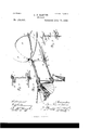
- FIG. l is a View in side elevation of an air-ship constructed in accordance with my invention
- Fig. 2, a plan thereof
- Fig. 3 a perspective of the front end
- Fig. 4 a vertical section through thecar or cab, showing the mechanism carried. thereby
- Fig. 5, a detail view showing the gearing and the lifting and lowering wings
- Fig. 6, a detail of the main-shaftshifting mechanism
- Fig. 7 a detail view of a portion of the propelling mechanism of wings
- Fig. 8 a detail view of the portion of the steering or guiding mechanism in the car or cab.
- My present invention in many respects is similar to that for which Letters Patent were issued to me September 29, 1891, No. 460,194.
- a balloon A, lowering and raising wings B, and propelling-wings (fare employed; but, unlike it, a car or ca D is used to materially augment its carryin capacity, and an elect-romotor is substituted for mail"- ual power to actuate the wings.
- the balloon A is of an elongated cylindrical shape with pointed ends.
- the cab D is suspended from it at its longitudinal center by means of a frame consisting of bands at of aluminum, encircling the balloon and suitable rods a of similar metal.
- the frame of the car consists of rods of aluminum, and around these is passed a covering of some light fabric, as oilcloth, having windows (I and doors d, the latter being arranged one on each side at the front and rear, respectively, but one being shown, however, in the drawings.
- a compartment D On the under side of the car is a compartment D, in which is a storage-battery E, and an electromotor F, deriving energy from the latter.
- the motor is connected by a sprocketchain f with a sprocket-wheel 9 upon a shaft G beneath and running parallel with the balloon, constituting the main shaft, and from which the various moving parts of the apparatus receive their motion, in the manner to be described.
- the wings B and O which I employ are precisely similar in construction and mode of operation to those setforth in my patent, and therefore in respect to these particulars will not be herein described.
- the raising and lowering wings B are provided in pairs at the front and rear ends of the car, each pair being hung and movable both on a single rod or bar b, as best shown in Fig. 5. These wings are operated from the main shaft G, as follows: Upon said shaft, within the car, but near each end, is a sprocket-wheel g, from which a sprocket-chain '9 runs to a wheel I) on the crank-shaft b of one wing B, and located on one side of the rod or bar 1).
- These wings are placed at the front of the machine upon a frame that is capable of lateral swing to enable the steering or guiding of the ship to be effected.
- Said frame II in the present instance is shaped like a U turned sidewise, and the ends of the horizontal portions 11 II havingopenings through which pass the down and up turned ends i, respectively, of supporting-bars I and I, where by the frame is supported and journaled. Said ends '2' also journal a vertical crankshaft K.
- cranks at its upper and lower ends which are connected by suitable pitmen, one with one pair of wings C and the other with the other, the connections between a crank and a pair of wings being the same as in my said patent.
- Both sets of wings C vibrate on asingle vertical rod 0, secured to the C-shapedwing-carrying frame II.
- the crank-shaft at its lower end carries a bevel gear-wheel it, which meshes with a bevel-gearg mi the front end of the main shaft G.
- an arm h On each side of the journaled end of the lower horizontal portion II extends an arm h at right angles thereto, which is connected by a rod with an arm Z on the top of a vertical shaft L, journaled at or near the front end of the cab and having attached to it an operating-lever Z by means of which the shaft may be rocked, and so the propelling-wings moved laterally to change the direction of the ship. If the lever Z be moved to the right, the ship will be turned to the left, and vice versa. A notched segment Z is provided, whereby the lever Z may be locked at the desired position to determine the course of the machine.
- the main shaft is made longitudinally movable, so that the bevel-gears 7t and 9 may be separated or thrown out of gear when the Wings are to be used.
- said shaft is provided with two collars g g", fixed thereto, between which is a third collar 9 having radial pins to engage the elongated openings m in a pivoted stopping-lever N.
- connection and disconnection of the wings B are effected by making the wheel g loose on the main shaft G and fixing to the latter a collar N, having a horizontal extension or pin a to be moved in and out an opening in said wheel by the reciprocation of the shaft.
- the wheel 9 is held against movement by a boxing or hanger O and an arm 0 thereon, which engage it on opposite sides. Any suitable means may be provided to lock the shaft in its shifted position to render the horizontallypropelling or the verticallymoving wings the operative ones.
- I provide horizontal extensions A A, arranged diametrically opposite each other upon the balloon A, the same being placed at its vertical center and fixedlyand rigidlysupported therefrom by a suitable frame-work constru cted of aluminum. These extensions A A are substantially as long as the balloon.
- To the rear end of each is pivoted a horizontal rudder A capable of being moved vertically, so as to determine the plane of the whole machine with reference to the horizon.
- Each rudder A is connected to an operating-lever A by a rod 1), the two levers A being hung on a common center within the cab and near its rear end. Suitable provision is made for locking these levers in a desired position.
- a screw or anger Q which is adapted to be screwed into the ground by means of a shaft R, geared to the main shaft.
- the lower end of the shaft R is enlarged, and in it is a long diametrical slot- 7', through which a transverse piece or pin 1 on the top of the auger R passes.
- springs S are attached at one end to the bottom of the car, while their free ends carry rollers s.
- ⁇ Vhat I claim is- 1.
- the two sets of propelling-wings arranged in pairs and operating alternately, substantially as shown and described.
- the swinging frame journaled at the front end thereof, the two pairs of wings arranged one above the other and vibrating on the same vertical axis, the crank-shaft connected to said wings, a motor to drive said shaft, and means to move the swinging frame, substantially as shown and described.
Landscapes
- Engineering & Computer Science (AREA)
- Mechanical Engineering (AREA)
- Aviation & Aerospace Engineering (AREA)
- Toys (AREA)
Description
(No Model.) 4 Sheets-Sheet 1.
B. P. BARNES. AIR SHIP.
' No. 478,905; Patented July 12, 1892.
(No Model.) 7 v I 4 eeee ts-Sheet 2.
B. P.' BARNES.
A I R S H I P- I No. 478,905; Patented July 12, 1892.
' nu. "Ml
WHUHJWH n h uuwm m THE noun 5 PEYEIIS co., mom-mum, wAsHmr-Yull, n.
(No Model.) 4 Sheets-Sheet 3.
B. P. BARNES.
AIR SHIP.
N0. 478,905. Patented July 12, 1892.
A I H L pwm y j/MW/ (No 1V IodeI.) 4SheetsSheet 4.
B. F. BARNES.
AIR SHIP.
Patented July 12,1892.
NITED STATES,
PATENT OFFICE.
BURR FRANK BARNES,
OF OIROLEVILLE, Ol-IIO.
AIR-SHIP.
SPECIFICATION forming part of Letters Patent No. 478,905, dated July 12, 1892. Application filed December 5, 1891- Serial No. 414,086. (No model.)
To all whom it may concern.-
- thereon, which form apart of this specification.
My invention relates to apparatus for aerial navigation, and has for its object to provide an air-shi p of large carrying capacity, strong, yet light in construction,'reliable in operation, and susceptible of easy and perfect control.
To these ends the invention consists in the apparatus constructed and arranged substantially as hereinafter specified, and shown in the drawings, in which 25 Figure l is a View in side elevation of an air-ship constructed in accordance with my invention; Fig. 2, a plan thereof; Fig. 3, a perspective of the front end; Fig. 4, a vertical section through thecar or cab, showing the mechanism carried. thereby; Fig. 5, a detail view showing the gearing and the lifting and lowering wings; Fig. 6, a detail of the main-shaftshifting mechanism; Fig. 7, a detail view of a portion of the propelling mechanism of wings, and Fig. 8 a detail view of the portion of the steering or guiding mechanism in the car or cab.
My present invention in many respects is similar to that for which Letters Patent were issued to me September 29, 1891, No. 460,194. Like it, a balloon A, lowering and raising wings B, and propelling-wings (fare employed; but, unlike it, a car or ca D is used to materially augment its carryin capacity, and an elect-romotor is substituted for mail"- ual power to actuate the wings. The balloon A is of an elongated cylindrical shape with pointed ends. The cab D is suspended from it at its longitudinal center by means of a frame consisting of bands at of aluminum, encircling the balloon and suitable rods a of similar metal. The frame of the car consists of rods of aluminum, and around these is passed a covering of some light fabric, as oilcloth, having windows (I and doors d, the latter being arranged one on each side at the front and rear, respectively, but one being shown, however, in the drawings.
On the under side of the car is a compartment D, in which is a storage-battery E, and an electromotor F, deriving energy from the latter. The motor is connected by a sprocketchain f with a sprocket-wheel 9 upon a shaft G beneath and running parallel with the balloon, constituting the main shaft, and from which the various moving parts of the apparatus receive their motion, in the manner to be described.
The wings B and O which I employ are precisely similar in construction and mode of operation to those setforth in my patent, and therefore in respect to these particulars will not be herein described. The raising and lowering wings B are provided in pairs at the front and rear ends of the car, each pair being hung and movable both on a single rod or bar b, as best shown in Fig. 5. These wings are operated from the main shaft G, as follows: Upon said shaft, within the car, but near each end, is a sprocket-wheel g, from which a sprocket-chain '9 runs to a wheel I) on the crank-shaft b of one wing B, and located on one side of the rod or bar 1). Thence from the lower side of said wheel I) said chain passes to the upper side of a wheel 19 on the crank-shaft of the other wing B, which wheel 19 is on the side of the rod 1) opposite the wheel I), and from said wheel b the chain passes over an idler 11 back to the wheel g. By this gearing the crank-shafts of the wings B'of a pair are moved in opposite directions. Two sets of pairs of propelling-wings O are provided with the present ship, differing in this respect from the patented apparatus; but both sets are arranged to vibrate on the same axis, being located one above the other. The
arrangement is such that while one is operating the other is being returned to position for becoming operative, a continuous motion of the propelling mechanism being thus insured. These wings, as in my patent, are placed at the front of the machine upon a frame that is capable of lateral swing to enable the steering or guiding of the ship to be effected. Said frame II in the present instance is shaped like a U turned sidewise, and the ends of the horizontal portions 11 II havingopenings through which pass the down and up turned ends i, respectively, of supporting-bars I and I, where by the frame is supported and journaled. Said ends '2' also journal a vertical crankshaft K. having cranks at its upper and lower ends which are connected by suitable pitmen, one with one pair of wings C and the other with the other, the connections between a crank and a pair of wings being the same as in my said patent. Both sets of wings C vibrate on asingle vertical rod 0, secured to the C-shapedwing-carrying frame II. The crank-shaft at its lower end carries a bevel gear-wheel it, which meshes with a bevel-gearg mi the front end of the main shaft G.
On each side of the journaled end of the lower horizontal portion II extends an arm h at right angles thereto, which is connected by a rod with an arm Z on the top of a vertical shaft L, journaled at or near the front end of the cab and having attached to it an operating-lever Z by means of which the shaft may be rocked, and so the propelling-wings moved laterally to change the direction of the ship. If the lever Z be moved to the right, the ship will be turned to the left, and vice versa. A notched segment Z is provided, whereby the lever Z may be locked at the desired position to determine the course of the machine.
As the lifting and lowering wings B are to be inoperative during the horizontal flight of the ship and the propelling-wings C inoperative during the vertical movement, the main shaft is made longitudinally movable, so that the bevel-gears 7t and 9 may be separated or thrown out of gear when the Wings are to be used. To shift said shaft longitudinally, it is provided with two collars g g", fixed thereto, between which is a third collar 9 having radial pins to engage the elongated openings m in a pivoted stopping-lever N. The connection and disconnection of the wings B are effected by making the wheel g loose on the main shaft G and fixing to the latter a collar N, having a horizontal extension or pin a to be moved in and out an opening in said wheel by the reciprocation of the shaft. The wheel 9 is held against movement by a boxing or hanger O and an arm 0 thereon, which engage it on opposite sides. Any suitable means may be provided to lock the shaft in its shifted position to render the horizontallypropelling or the verticallymoving wings the operative ones.
To aid the flotation of the apparatus, I provide horizontal extensions A A, arranged diametrically opposite each other upon the balloon A, the same being placed at its vertical center and fixedlyand rigidlysupported therefrom by a suitable frame-work constru cted of aluminum. These extensions A A are substantially as long as the balloon. To the rear end of each is pivoted a horizontal rudder A capable of being moved vertically, so as to determine the plane of the whole machine with reference to the horizon. Each rudder A is connected to an operating-lever A by a rod 1), the two levers A being hung on a common center within the cab and near its rear end. Suitable provision is made for locking these levers in a desired position.
As a means of anchoring or securing the ship to the earth, I provide at each end a screw or anger Q, which is adapted to be screwed into the ground by means of a shaft R, geared to the main shaft. The lower end of the shaft R is enlarged, and in it is a long diametrical slot- 7', through which a transverse piece or pin 1 on the top of the auger R passes. By this arrangement the shaft and the auger are coupled so that the latter is allowed to descend or ascend as the shaft rotates it in one direction or the other. Suitable means are to be provided to connect and to disconnect the shafts R from the main shaft.
To avoid undue shock or jar on the descent of the ship to the earth, springs S are attached at one end to the bottom of the car, while their free ends carry rollers s.
I contemplate substituting for the lifting and lowering wings B devices similar to the scre\ propellers, which will be located in the same place as said wings and driven from the main shaft.
\Vhat I claim is- 1. In combination with the buoyant device, the two sets of propelling-wings arranged in pairs and operating alternately, substantially as shown and described.
2. In combination with the buoyant device, the two sets of propelling-wings arranged in pairs and vibrating on the same vertical axis, the crank-shaft connected with said Wings, and suitable means to operate said shaft, substantially as described.
In combination with the buoyant device, the swinging frame journaled at the front end thereof, the two pairs of wings arranged one above the other and vibrating on the same vertical axis, the crank-shaft connected to said wings, a motor to drive said shaft, and means to move the swinging frame, substantially as shown and described.
4. In combination, the balloon, the cab supported thereby, the compartment beneath the cab, the battery and the motor in the latter, the main shaft, the vertically-vibrating wings geared to the latter, and the horizontally-vibratory wings likewise geared thereto, substantially as shown.
5. In combination, the balloon, the cab supported thereby, the motor in the cab, the main shaft driven from the motor, the verticallyanovable wings, the horizontally-movable wings driven both but dissimultaneously by said shaft, the swinging frame carrying the latter wings, and means for moving said frame from within the cab, substantially as shown and described.
6. In combination, the cab, the pair of lifting and lowering wings, the drivingshaft, the
IIO
scribed.
8. In combination, the buoyant device, the bars thereon with inturned ends, the swinging frame journaled on said ends, the crank-shaft journaled in the latter, the wings on said frame, and the steering device connected to said arms, substantially as shown and described.
9. In combination with a buoyant device having means for its propulsion, consisting in part in a shaft,.the anchoring device adapted to be operated by said shaft, consisting of a screw or anger and the rotary shaft,
connected thereto by a pin and slot, substantially as shown and described.
In testimony whereof I affix my signature in presence of two witnesses.
BURR FRANK BARNES. Witnesses:
I. B. BARNES, WILLIAM BRANNAN.
Publications (1)
| Publication Number | Publication Date |
|---|---|
| US478905A true US478905A (en) | 1892-07-12 |
Family
ID=2547759
Family Applications (1)
| Application Number | Title | Priority Date | Filing Date |
|---|---|---|---|
| US478905D Expired - Lifetime US478905A (en) | Air-ship |
Country Status (1)
| Country | Link |
|---|---|
| US (1) | US478905A (en) |
-
0
- US US478905D patent/US478905A/en not_active Expired - Lifetime
Similar Documents
| Publication | Publication Date | Title |
|---|---|---|
| US478905A (en) | Air-ship | |
| US717457A (en) | Amusement apparatus. | |
| US365133A (en) | kessler | |
| US920792A (en) | Winged propelling and guiding mechanism for air-ships. | |
| US1189612A (en) | Flying-machine. | |
| US792154A (en) | Aeronautic apparatus. | |
| US464851A (en) | Aerial machine | |
| US1028010A (en) | Aerial trolley. | |
| US1315586A (en) | wilson | |
| US1082472A (en) | Airship. | |
| US929196A (en) | Suspended railway. | |
| US540105A (en) | Lerie | |
| US1006967A (en) | Propelling mechanism for aerodromes. | |
| US1112352A (en) | Current-motor. | |
| US981714A (en) | Aeroplane flying-machine. | |
| US518925A (en) | Elevated railway | |
| US471452A (en) | Elevated railroad | |
| US530219A (en) | Orafeldt | |
| US779126A (en) | Air-ship. | |
| US774643A (en) | Air-ship. | |
| US226223A (en) | Dredging-machine | |
| US991528A (en) | Aerial navigation. | |
| US1069823A (en) | Flying-machine. | |
| US383889A (en) | Air-ship | |
| US1052204A (en) | Automatic balancing and horizontal sustaining aeroplane. |