US4784895A - Magnetic recording medium and process for the preparation of the same - Google Patents
Magnetic recording medium and process for the preparation of the same Download PDFInfo
- Publication number
- US4784895A US4784895A US07/172,812 US17281288A US4784895A US 4784895 A US4784895 A US 4784895A US 17281288 A US17281288 A US 17281288A US 4784895 A US4784895 A US 4784895A
- Authority
- US
- United States
- Prior art keywords
- magnetic recording
- magnetic
- recording layer
- longitudinal length
- coercive force
- Prior art date
- Legal status (The legal status is an assumption and is not a legal conclusion. Google has not performed a legal analysis and makes no representation as to the accuracy of the status listed.)
- Expired - Lifetime
Links
Images

Classifications
-
- G—PHYSICS
- G11—INFORMATION STORAGE
- G11B—INFORMATION STORAGE BASED ON RELATIVE MOVEMENT BETWEEN RECORD CARRIER AND TRANSDUCER
- G11B5/00—Recording by magnetisation or demagnetisation of a record carrier; Reproducing by magnetic means; Record carriers therefor
- G11B5/62—Record carriers characterised by the selection of the material
- G11B5/68—Record carriers characterised by the selection of the material comprising one or more layers of magnetisable material homogeneously mixed with a bonding agent
- G11B5/70—Record carriers characterised by the selection of the material comprising one or more layers of magnetisable material homogeneously mixed with a bonding agent on a base layer
- G11B5/716—Record carriers characterised by the selection of the material comprising one or more layers of magnetisable material homogeneously mixed with a bonding agent on a base layer characterised by two or more magnetic layers
-
- Y—GENERAL TAGGING OF NEW TECHNOLOGICAL DEVELOPMENTS; GENERAL TAGGING OF CROSS-SECTIONAL TECHNOLOGIES SPANNING OVER SEVERAL SECTIONS OF THE IPC; TECHNICAL SUBJECTS COVERED BY FORMER USPC CROSS-REFERENCE ART COLLECTIONS [XRACs] AND DIGESTS
- Y10—TECHNICAL SUBJECTS COVERED BY FORMER USPC
- Y10S—TECHNICAL SUBJECTS COVERED BY FORMER USPC CROSS-REFERENCE ART COLLECTIONS [XRACs] AND DIGESTS
- Y10S428/00—Stock material or miscellaneous articles
- Y10S428/90—Magnetic feature
-
- Y—GENERAL TAGGING OF NEW TECHNOLOGICAL DEVELOPMENTS; GENERAL TAGGING OF CROSS-SECTIONAL TECHNOLOGIES SPANNING OVER SEVERAL SECTIONS OF THE IPC; TECHNICAL SUBJECTS COVERED BY FORMER USPC CROSS-REFERENCE ART COLLECTIONS [XRACs] AND DIGESTS
- Y10—TECHNICAL SUBJECTS COVERED BY FORMER USPC
- Y10T—TECHNICAL SUBJECTS COVERED BY FORMER US CLASSIFICATION
- Y10T428/00—Stock material or miscellaneous articles
- Y10T428/24—Structurally defined web or sheet [e.g., overall dimension, etc.]
- Y10T428/24942—Structurally defined web or sheet [e.g., overall dimension, etc.] including components having same physical characteristic in differing degree
-
- Y—GENERAL TAGGING OF NEW TECHNOLOGICAL DEVELOPMENTS; GENERAL TAGGING OF CROSS-SECTIONAL TECHNOLOGIES SPANNING OVER SEVERAL SECTIONS OF THE IPC; TECHNICAL SUBJECTS COVERED BY FORMER USPC CROSS-REFERENCE ART COLLECTIONS [XRACs] AND DIGESTS
- Y10—TECHNICAL SUBJECTS COVERED BY FORMER USPC
- Y10T—TECHNICAL SUBJECTS COVERED BY FORMER US CLASSIFICATION
- Y10T428/00—Stock material or miscellaneous articles
- Y10T428/25—Web or sheet containing structurally defined element or component and including a second component containing structurally defined particles
-
- Y—GENERAL TAGGING OF NEW TECHNOLOGICAL DEVELOPMENTS; GENERAL TAGGING OF CROSS-SECTIONAL TECHNOLOGIES SPANNING OVER SEVERAL SECTIONS OF THE IPC; TECHNICAL SUBJECTS COVERED BY FORMER USPC CROSS-REFERENCE ART COLLECTIONS [XRACs] AND DIGESTS
- Y10—TECHNICAL SUBJECTS COVERED BY FORMER USPC
- Y10T—TECHNICAL SUBJECTS COVERED BY FORMER US CLASSIFICATION
- Y10T428/00—Stock material or miscellaneous articles
- Y10T428/26—Web or sheet containing structurally defined element or component, the element or component having a specified physical dimension
- Y10T428/263—Coating layer not in excess of 5 mils thick or equivalent
- Y10T428/264—Up to 3 mils
- Y10T428/265—1 mil or less
Definitions
- the present invention relates to a magentic recording medium and a process for the preparation of the same. More particularly, the invention relates to a magnetic recording medium having a magnetic recording layer consisting of at least two layers which is improved in frequency characteristics and a process for the preparation of the same.
- Magnetic recording media such as an audio tape and a video tape are desired to be excellent in various properties in recent years.
- an audio cassette tape is required to show low noise, well-balanced frequency characteristics and high output in all frequency bands.
- Such requirement for the audio cassette tape tends to increase more and more because various developments such as a development of digital system have been recently made in pursuit of ultra hi-fi audio sources or extremely low noise audio sources as shown in a compact disc.
- a video tape is also required to show higher video output and lower noise.
- a magnetic tape having a magnetic recording layer which consists of two or more layers has been proposed.
- an upper recording layer is made to have a higher coercive force than that of a lower recording layer so as to give excellent characteristics in the high-frequency band to the upper recording layer, and thereby to obtain a high output level in all frequency bands in the resulting medium.
- such conventional tape does not have a uniform reproduction output in all frequency bands because of the distinct separation between the upper and lower recording layers, and for example, the reproduction output of the tape lowers in the mid frequency band or partially decreases in the extreme in the reproduction procedure.
- the conventional magnetic tape having plural recording layers is disadvantageous from the viewpoint of practical operation and cost for the preparation (for example, a number of coating procedures are required for the tape), although the frequency characteristics are enhanced in accordance with the number of recording layers.
- magnetic particles having a short length in the longitudinal direction are incorporated into the upper recording layer for the purpose of reducing a noise level and magnetic particles having a long length in the longitudinal direction are incorporated into in the lower recording layer for the purpose of increasing frequency characteristics in the high-frequency band, in addition to the above-mentioned consideration on the coercive force.
- the magnetic particles having a long length in the longitudinal direction is used for the lower recording layer, the surface smoothness of the resulting lower recording layer is decreased more than the case of using magnetic particles having a short length in the longitudinal direction.
- satisfactory smoothness is hardly given to the surface of the upper recording layer.
- the above-mentioned method i.e., method of using magnetic particles of the specific length in the longitudinal direction in each of the upper and lower recording layers
- the frequency characteristics deteriorate in the high-frequency band in the case of an audio tape
- the S/N ratio decreases because of lowering of sensitivity and increase of noises in the case of a video tape.
- the object of the invention is to provide a magnetic recording medium such as a magnetic tape which has a low noise level and a high sensitivity as well as the improved reproduction output in all frequency bands and a process for the preparation of said magnetic recording medium.
- a magnetic recording medium comprising a nonmagnetic support, a first magnetic recording layer and a second magnetic recording layer, superposed in order, wherein:
- a coercive force of the second magnetic recording layer (Hc 2 ) is in the range of 400 to 2,000 Oe, a ratio of said coercive force (Hc 2 ) to a coercive force of the first magnetic recording layer (Hc 1 ), namely Hc 2 /Hc 1 , being in the range of 1.0 to 2.5;
- a mean longitudinal length of a magnetic powder contained in the second magnetic recording layer is not longer than 0.35 ⁇ m, a ratio of said mean longitudinal length (S 2 ) to a mean longitudinal length of a magnetic powder contained in the first magnetic recording layer (S 1 ), namely S 2 /S 1 , being in the range of 0.4 to 1.0;
- a mixed area of compositions of the first magnetic recording layer and the second magnetic recording layer which has a thickness of 0.1 to 1.1 ⁇ m is provided between the first and second magnetic recording layers.
- a magnetic paint for the formation of a first magnetic recording layer over a surface of a non-magnetic support under running or travelling of the support to give a coated layer of the magnetic paint
- a magnetic recording layer is wet means that the magnetic recording layer contains a solvent, and particularly means that the magnetic recording layer is dried to such a degree that particles of the magnetic powder can be easily inverted in the magnetic recording layer when a bar magnet is placed in vicinity of the recording layer.
- a first magnetic recording layer (lower magnetic recording layer) and a second magnetic recording layer (upper magnetic recording layer), each layer being specified in its properties such as a coercive force and a mean longitudinal length of magnetic powder particles contained therein, are superposed on the nonmagnetic support, and a mixed area of compositions of the first and second magnetic recording layers having a thickness of 0.1 to 1.1 ⁇ m is provided between the two magnetic recording layers.
- the mixed area can be formed by the above-mentioned process of the invention between the first and second recording layers.
- the provision of the mixed area also contributes to lowering of a noise level and enhancement of a sensitivity of the resulting medium.
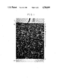
- FIG. 1 is a photo which shows sectional schematic view obtained by photographing a section of a magnetic recording layer prepared in Example 3 by means of a scanning type electron microscope.
- FIG. 2 is a photo which shows sectional schematic view obtained by photographing a section of a magnetic recording layer prepared in Comparison Example 1 by means of a scanning type electron microscope.
- the magnetic recording medium of the present invention can be prepared, for example, by the following process.
- a magnetic paint for the formation of a first magnetic recording layer which contains a magnetic powder in a binder solution is coated over a nonmagnetic support, and while the coated layer is wet, a magnetic paint for the formation of a second magnetic recording layer which contains a magnetic powder in a binder solution is applied onto the coated layer for the formation of the first magnetic recording layer, to give a coated layer of the magnetic paint for the formation of a second magnetic recording layer.
- the surface of the nonmagnetic support is placed in close vicinity of an orientation magnet to invert particles of the magnetic powder contained in each of the magnetic recording layers, whereby a mixed area of compositions of the first and second magnetic recording layers is provided between the two magnetic recording layers. Otherwise, the mixed area is provided between the two recording layers by utilizing a shearing force occurring in the coating procedure of the magnetic paint for the formation of a second magnetic recording layer, or decreasing a viscosity of each magnetic paint for the first and second magnetic recording layers and thereby bringing about a convection in the drying procedure of the coated layers of the two magnetic paints.
- the thickness of the mixed area provided between the first and second magnetic recording layers is required to be in the range of 0.1 to 1.1 ⁇ m.
- the thickness of the mixed area is smaller than 0.1 ⁇ m, the continuous variation of the coercive force in the depth direction becomes too small, and as a result, there arises deterioration of frequency characteristics such as lowering of reproduction output or large fluctuation of output level.
- the thickness thereof exceeds 1.1 ⁇ m, the output in the specific frequency band which depends on the lower magnetic recording layer cannot be sufficiently given to the resulting medium.
- the coercive force of the second magnetic recording layer (Hc 2 ) is required to be in the range of 400 to 2,000 Oe, and a ratio of said coercive force (Hc 2 ) to a coercive force of the first magnetic recording layer (Hc 1 ), namely Hc 2 /Hc 1 , is required to be in the range of 1.0 to 2.5.
- Hc 2 /Hc 1 is less than 1.0, a high output can be hardly obtained in the wide frequency band.
- Hc 2 /Hc 1 exceeds 2.5, the frequency characteristics markedly deteriorate (i.e., output level strikingly lowers) in the mid frequency band because the difference of the recording current running on a magnetic head is too large.
- the coercive force of the second magnetic recording layer (upper recording layer) is less than 400 Oe, an output of the high-frequency band can be hardly obtained.
- the coercive force thereof exceeds 2,000 Oe, the recorded signal cannot be sufficiently erased using a conventional head.
- the mean longitudinal length of the magnetic particles contained in the second magnetic recording layer (S 2 ) is required to be not longer than 0.35 ⁇ m, and a ratio of said mean longitudinal length (S 2 ) to a mean longitudinal length of the magnetic particles contained in the first magnetic recording layer (S 1 ), namely S 2 /S 1 , is required to be in the range of 0.4 to 1.0.
- S 2 /S 1 exceeds 1.0, relatively large particles of the magnetic powder exist in the vicinity of a magnetic head to cause occurrence of noises and deterioration of surface smoothness of the resulting medium.
- S 2 /S 1 is less than 0.4, relatively large particles of the magnetic powder exist in the first magnetic recording layer, resulting in occurrence of noises.
- the mean longitudinal length of the magnetic particles (S 2 ) employable for the second magnetic recording layer (upper recording layer) is required not longer than 0.35 ⁇ m as described above, and preferably not longer than 0.30 ⁇ m.
- the mean longitudinal length thereof exceeds 0.35 ⁇ m the resulting recording medium suffers large noises and deteriorates in the surface smoothness.
- a magnetic paint for the formation of a first magnetic recording layer (lower magnetic recording layer) is coated over the nonmagnetic support under running of the support. While the coated layer is wet, a magnetic paint for the formation of a second magnetic recording layer (upper magnetic recording layer) is coated thereon. While both of the coated layers are wet, a magnetic orientation for the magnetic particles contained in those layers is performed by the use a cobalt bar magnet (first magnetic orientation).
- the bar magnet used for the magnetic orientation is preferably arranged vertically against the surface of the nonmagnetic support in such a manner that one pole of the bar magnet is placed in close vicinity of the surface of the support not facing the magnetic recording layer.
- the mixed area can be provided between the first and second magnetic recording layers.
- a magnetic paint for the formation of a first magnetic recording layer (lower magnetic recording layer) is coated over the nonmagnetic support under running of the support. While the coated layer is wet, a magnetic paint for the formation of a second magnetic recording layer (upper magnetic recording layer) is coated thereon. While both of the coated layers are wet, a magnetic orientation is carried out by the use two or more bar magnets to perform at least two times of inversions of the magnetic particles contained in the coated layers (the same inversion as described in the method (1)). Thus, the mixed area can be provided between the first and second magnetic recording layers.
- the plural bar magnets are arranged at regular intervals (preferably an interval of 5 to 15 cm) in the running direction of the support in such a manner that the poles of the magnets are placed in close vicinity of the surface of the support not facing the magnetic recording layer.
- the bar magnets may be arranged in such a manner that the adjoining poles of the bar magnets are the same as each other or different from each other. From the viewpoint of effective inversion of the magnetic particles, the adjoining poles of the magnets are preferably different from each other.
- a magnetic paint for the formation of a first magnetic recording layer (lower magnetic recording layer) is coated over the nonmagnetic support. While the coated layer is wet, a magnetic paint for the formation of a second magnetic recording layer (upper magnetic recording layer) is coated thereon.
- a shearing force is applied to the interface between the coated layers of the magnetic paints for the first and second magnetic recording layers. Utilizing the shearing force, the mixed area can be provided between the first and second magnetic recording layers.
- a method of using a doctor blade in a coating apparatus under the specific conditions.
- a doctor blade having a wide coating surface is used to take a long period of time for shearing, or a doctor blade provided with a depressed portion on its coating surface is used to vary the shearing force.
- a doctor blade is used with applying ultrasonic vibration to the blade in the coating procedure to vary the shearing force.
- the thickness of the resulting mixed area can be made larger, because the shearing force becomes greater as the viscosity of the magnetic paint for the upper recording layer increases. Accordingly, the thickness of the mixed area can be optionally determined to a certain level by combining any one of the above-described methods (1) and (2), both utilizing a bar magnet, and the method of utilizing a shearing force given by a magnetic paint having a high viscosity.
- a magnetic paint for the formation of a first magnetic recording layer (lower magnetic recording layer) is coated over the nonmagnetic support. While the coated layer is wet, a magnetic paint for the formation of a second magnetic recording layer (upper magnetic recording layer) is coated thereon, and then both of the coated layers are dried. In the drying procedure, a convection phenomenon takes place in the coated layers. Utilizing the convection phenomenon, the mixed area can be provided between the first and second magnetic recording layers. In this method, each of the magnetic paints for the upper and lower recording layers is required to have a viscosity of not more than 20 P.
- the magnetic recording layer comprising the first and second recording layers is subjected to a magnetic orientation by passing it through an electromagnet (solenoid). Thereafter, the nonmagnetic support having the magnetic recording layer thereon is subjected to various treatments which are conventionally used for the preparation of magnetic recording media, to prepare a magnetic recording medium of the present invention.
- nonmagnetic support examples include films or sheets made of synthetic resins such as polyester resins (e.g., polyethylene terephthalate (PET) and polyethylene naphthalate), polyolefin resins (e.g., polypropylene), cellulose derivatives (e.g., cellulose triacetate and cellulose diacetate), vinyl resins (e.g., polyvinyl chloride and polyvinylidene chloride), polycarbonate resins, polyamide resins, polyimide resins and polyamideimide resins; nonmagnetic metal foils such as aluminum foil and copper foil; metal foils such as stainless foil; papers; and ceramic sheets.
- synthetic resins such as polyester resins (e.g., polyethylene terephthalate (PET) and polyethylene naphthalate), polyolefin resins (e.g., polypropylene), cellulose derivatives (e.g., cellulose triacetate and cellulose diacetate), vinyl resins (e.g., polyvinyl chlor
- the magnetic recording layer of the magnetic recording medium according to the invention comprises a binder and a magnetic powder dispersed therein.
- a magnetic powder there is no specific limitation on the magnetic powder employable in the invention.
- the magnetic powder include ⁇ -Fe 2 O 3 , Co-containing ⁇ -Fe 2 O 3 , Fe 3 O 4 , Co-containing Fe 3 O 4 , CrO 2 , Co-Ni-P, Fe-Co-Ni.
- a binder solution emplyable for preparing the magnetic paint of the magnetic recording layer according to the invention contains a resin component, a solvent and, if necessary, other additives such as a lubricant and an abrasive.
- thermoplastic resins thermo-setting resins, reaction curing resins and mixtures thereof which are conventionally used for the preparation of magnetic recording media.
- the resin components include vinyl chloride copolymers such as a vinyl chloride/vinyl acetate copolymer, a vinyl chloride/vinyl acetate/vinyl alcohol copolymer, a vinyl chloride/vinyl acetate/acrylic acid copolymer, a vinyl chloride/vinylidene chloride copolymer, a vinyl chloride/acrylonitrile copolymer, an ethylene/vinyl acetate copolymer and a vinyl chloride copolymer introduced with a polar group (e.g., --SO 3 Na or --SO 2 Na) and an epoxy group; cellulose derivatives such as nitrocellulose resins; acrylic resins; polyvinyl acetal resins; polyvinyl butyral resins; epoxy resins; phenoxy resins; and poly
- a polyisocyanate compound is generally employed as the curing agent.
- the polyisocyanate compound can be selected from those generally used for curing polyurethane resin, etc.
- a compound having a reactive double bond e.g., urethane acrylate
- a compound having a reactive double bond e.g., urethane acrylate
- Examples of the solvents employable for preparing the magnetic paint include ketones such as acetone, methyl ethyl ketone, methyl isobutyl ketone, ethyl isobutyl ketone and cyclohexanone; esters such as methyl acetate, ethyl acetate, butyl acetate, glycol acetate monoethyl ether; glycol ethers such as ether, glycol dimethylether and dioxane; aromatic hydrocarbons such as benzene, toluene and xylene; chlorinated hydrocarbons such as methylene chloride, ethylene chloride, carbon tetrachloride, chloroform, ethylenechlorohydrin and dichlorobenzene.
- Preferred are polar solvents such as ketones or solvents containing a polar solvent. These solvents can be employed independently or in combination.
- the above-mentioned magnetic powder is homogeneously kneaded and dispersed in the binder solution.
- the magnetic powder is generally pre-dispersed in the binder solution using a two-roll mill, a three-roll mill, an open kneader, a pressure kneader or a continuous kneader and then again dispersed therein using a sand grinder or a ball mill.
- the magnetic paint may be optionally incorporated with a variety of additives such as an abrasive, a lubricant, a dispersing agent and an antistatic agent according to the conventional manner depending on the purpose.
- additives such as an abrasive, a lubricant, a dispersing agent and an antistatic agent according to the conventional manner depending on the purpose.
- the coating of the magnetic paint can be carried out by the conventional coating methods such as an air doctor coating, a blade coating, a rod coating, an extrusion coating, an air knife coating, a squeeze coating, an impregnation coating, a reverse roll coating, a transfer roll coating, a gravure coating, a kiss coating, a cast coating, a spray coating and a spin coating. Details of those coating methods are concretely described in "Coating Technology", pp 253-277, published by Asakura Shoten, Mar. 20, 1971.
- a magnetic recording medium having a magnetic recording layer which consists of two layers of an upper and lower layers.
- any other magnetic recording medium having a magnetic recording layer consisting of three or more layers can be also applied to the present invention, provided that the magnetic recording layer comprises at least two layers specified in the aforementioned characteristics.
- the components excluding polyisocyanate were kneaded in a ball mill for 48 hours to give a mixture.
- polyisocyanate was added to the mixture.
- polyisocyanate was added to the mixture and they were kneaded in the ball mill for 20 minutes to give a dispersion.
- Each of the dispersions was filtered over a filter having a mean pore size of 1 ⁇ m to prepare two kinds of magnetic paints, namely, a magnetic paint A for the formation of a first magnetic recording layer and a magnetic paint B for the formation of a second magnetic recording layer.
- the obtained magnetic paint A was coated over a surface of a polyethylene terephthalate support (thickness: 12 ⁇ m) under running the support at a speed of 60 m/min. by means of a reverse roll in such a manner that the coated layer would have thickness of 4 ⁇ m in dry basis. While the coated layer of the magnetic paint A was wet, the magnetic paint B was coated thereon in such a manner that the coated layer of the magnetic paint B would have thickness of 1.2 ⁇ m in dry basis by means of a reverse roll.
- the support having the coated layers thereon was passed on a magnet under the following conditions (a) to provide a mixed area of the two compositions of the magnetic paints A and B between the coated layer of the magnetic paint A and the coated layer of the magnetic paint B.
- One cobalt bar magnet (3,000 gauss) is arranged on a surface of the support not facing the magnetic recording layer in such a manner that the bar magnet is vertical against the surface of the support and N pole of the bar magnet is in close vicinity of the surface of the support.
- the support with the coated layers was subjected to a magnetic orientation by means of a direct current type electromagnet, and then subjected to drying.
- the resulting sheet was subjected to a supercalendering treatment, and then split to give an audio cassette tape having a width of 3.8 mm.
- Each viscosity set forth in Table 1 is a value measured by a tubular rotating viscometer (VS-H1 type, produced by Shibaura System Co., Ltd.).
- Example 1 The procedure of Example 1 was repeated except for replacing the conditions (a) with the following conditions (b) for providing a mixed area of the compositions of the magnetic paints A and B, to prepare an audio cassette tape.
- Each magnet 3,000 gauss
- a pole of each magnet is in close vicinity of the surface of the support, and adjoining poles of the bar magnets are different from each other with respect to the polarity.
- Example 1 The procedure of Example 1 was repeated except for using a magnetic paint B1 having the viscosity set forth in Table 1 instead of the magnetic paint B, to prepare an audio cassette tape.
- the magnetic paint B1 has the same composition as that of the magnetic paint B except for varying the amounts of methyl ethyl ketone and butyl acetate to 70 parts and 90 parts, respectively.
- Example 3 The procedure of Example 3 was repeated except for using a magnetic paint A1 having the viscosity set forth in Table 1 instead of the magnetic paint A, to prepare an audio cassette tape.
- the magnetic paint A1 has the same composition as that of the magnetic paint A except for varying the amounts of methyl ethyl ketone and butyl acetate to 95 parts and 105 parts, respectively.
- the magnetic paint A for the formation of a first magnetic recording layer was coated over a surface of a polyethylene terephthalate support (thickness: 12 ⁇ m) under running the support at 60 m/min. by means of a reverse roll to give a coated layer having thickness of 4 ⁇ m in dry basis.
- the support having the coated layer thereon was successively subjected to a magnetic orientation, a drying procedure and a supercalendering treatment, and then allowed to stand in a drying room at 70° C. for 24 hours to heat-cure the first magnetic recording layer.
- a magnetic paint B for the formation of a second magnetic recording layer by means of a reverse roll to give a coated layer of the magnetic paint B having thickness of 1.2 ⁇ m in dry basis.
- the resulting sheet was successively subjected to a magnetic orientation, a drying procedure and a supercalendering treatment. The sheet was then split to give an audio cassette tape having a width of 3.8 mm.
- Example 1 The procedure of Example 1 was repeated except for not providing a mixed area of the compositions of the magnetic paints A and B, to prepare an audio cassette tape.
- Example 4 The procedure of Example 4 was repeated except for replacing the conditions (a) with the conditions (b) for providing a mixed area of the compositions of the magnetic paints A and B, to prepare an audio cassette tape.
- Signals of various frequencies (315 Hz, 500 Hz, 1 kHz, 2 kHz, 3 kHz, 5 kHz and 10 kHz) were recorded at -20 dB on each tape, and the recorded signals were reproduced to measure reproduction output of each frequency.
- the output level was expressed by a relative value based on the output level of 315 Hz being 0 dB.
- the sensitivity of each tape was measured by means of a commercial tape deck (582 type of Nakamichi Co., Ltd.). The sensitivity was expressed by a relative value based on a sensitivity of a commercial tape (FR-II of Fjui Photo Film Co., Ltd.) at high-position being 0 dB.
- a signal of 10 kHz was recorded simultaneously on each tape at -20 dB for 3 minutes, and the output of the recorded signal was measured. The measurement was done at three positions for each tape to determine the output fluctuation of the tape.
- each magnetic recording layer and the mixed area, the coercive force of each magnetic recording layer and the mean longitudinal length of magnetic particles contained therein with respect to the magnetic recording media obtained in Examples 1 to 4 and Comparison Examples 1 to 3 are set forth in Table 2, in which each of Hc 2 , Hc 1 , S 2 and S 1 means a coercive force of the second magnetic recording layer, a coercive force of the first magnetic recording layer, a mean longitudinal length of magnetic particles contained in the second magnetic recording layer, and a mean longitudinal length of magnetic particles contained in the first magnetic recording layer, respectively.
- the audio tapes of Comparison Examples 1 and 2 each having no mixed area, showed lowering of output level in the mid frequency band, namely 1 to 3 kHz.
- the audio tape of Comparison Example 3 having a mixed area of large thickness was decreased in the sensitivity, and accordingly it was confirmed that an audio tape having a mixed area of large thickness is unfavorable.
- the audio tape comprises a ferromagnetic powder 1, a binder 2, a nonmagnetic support 3, a first magnetic recording layer 4 and a second magnetic recording layer 5.
- the audio tape further comprises a mixed area 6. As shown in FIG. 1 according to Example 3, an area containing the compositions of the first and second magnetic recording layers in the mixed form (i.e., mixed area 6) was observed, but such area was not observed in FIG. 2 according to Comparison Example 1.
- the components excluding polyisocyanate were kneaded in a ball mill for 48 hours to give a mixture.
- polyisocyanate was added to the mixture and they were kneaded for 20 minutes in the ball mill to give a dispersion.
- Each of the dispersions was filtrated over a filter having a mean pore size of 1 ⁇ m to prepare two kinds of magnetic paints, namely, a magnetic paint C for the formation of a first magnetic recording layer and a magnetic paint D for the formation of a second magnetic recording layer.
- the obtained magnetic paint C was coated over a surface of a polyethylene terephthalate support (thickness: 14 ⁇ m) under running the support at a speed of 60 m/min. by means of a reverse roll in such a manner that the coated layer would have thickness of 3 ⁇ m in dry basis. While the coated layer of the magnetic paint C was wet, the magnetic paint D was coated thereon in such a manner that the coated layer of the magnetic paint D would have thickness of 1.0 ⁇ m in dry basis by means of a reverse roll. While both of the coated layers of the magnetic paints C and D were wet, the support having the coated layers thereon was passed on a magnet under the following conditions (a) to provide a mixed area of the two compositions of the magnetic paints.
- One cobalt bar magnet (3,000 gauss) is arranged on a surface of the support not facing the magnetic recording layer in such a manner that the bar magnet is vertical against the surface of the support and N pole of the bar magnet is in close vicinity of the surface of the support.
- the support with the coated layers was subjected to a magnetic orientation by means of a direct current type electromagnet, and the subjected to drying.
- the resulting sheet was subjected to a supercalendering treatment, and then slit to give a video cassette tape having a width of 1/2 inch.
- Each viscosity set forth in Table 4 is a value measured by a tubular rotating viscometer (VS-H1 type, produced by Shibaura System Co., Ltd.).
- Example 5 The procedure of Example 5 was repeated except for replacing the conditions (a) with the following conditions (b) for providing a mixed area of the compositions of the magnetic paints C and D, to prepare a video cassette tape.
- Each magnet 3,000 gauss
- a pole of each magnet is in close vicinity of the surface of the support, and adjoining poles of the bar magnets are different from each other in the polarity.
- Example 5 The procedure of Example 5 was repeated except for using a magnetic paint D1 having the viscosity set forth in Table 4 instead of the magnetic paint D, to prepare a video cassette tape.
- the magnetic paint D1 has the same composition as that of the magnetic paint D except for varying the amounts of methyl ethyl ketone and butyl acetate to 70 parts and 90 parts, respectively.
- Example 7 The procedure of Example 7 was repeated except for using a magnetic paint C1 having the viscosity set forth in Table 4 instead of the magnetic paint C, to prepare a video cassette tape.
- the magnetic paint C1 has the same composition as that of the magnetic paint C except for varying the amounts of methyl ethyl ketone and butyl acetate to 95 parts and 105 parts, respectively.
- the magnetic paint C for the formation of a first magnetic recording layer was coated over a surface of a polyethylene terephthalate support (thickness: 14 ⁇ m) under running the support at 60 m/min. by means of a reverse roll to give a coated layer having thickness of 3 ⁇ m in dry basis.
- the support having the coated layer thereon was successively subjected to a magnetic orientation, a drying procedure and a supercalendering treatment, and then allowed to stand in a drying room at 70° C. for 24 hours to heat-cure the first magnetic recording layer.
- a magnetic paint D for the formation of a second magnetic recording layer by means of a reverse roll to give a coated layer of the magnetic paint D having thickness of 1.0 ⁇ m in dry basis.
- the resulting sheet was successively subjected to a magnetic orientation, a drying procedure and a supercalendering treatment. The sheet was then slit to give a video cassette tape having a width of 1/2 inch.
- Example 5 The procedure of Example 5 was repeated except for not providing a mixed area of the compositions of the magnetic paints C and D, to prepare a video cassette tape.
- Example 8 The procedure of Example 8 was repeated except for replacing the conditions (a) with the conditions (b) for providing a mixed area of the compositions of the magnetic paints C and D, to prepare a video cassette tape.
- each magnetic recording layer and the mixed area was measured in the same manner as for the aforementioned audio cassette tapes.
- the video output was expressed by a relative value based on a commercial video cassette tape (Super HG of VHS type, available from Fuji Photo Film Co., Ltd.) being 0 dB.
- the C/N ratio was expressed by a ratio of noise at an output of 4 MHz to noise at a frequency distant from 4 MHz by 1 MHz.
- e 1 is a value of an output obtained by recording a signal on a tape at a specified recording power and then passing a reproduction output of the recorded signal through a 1/3 octave filter
- e 2 is a value of an output obtained by recording a signal on a tape at a specified recording power, erasing the recorded signal at a specified erasing current and then passing the reproduction output through a 1/3 octave filter.
- each of Hc 2 , Hc 1 , S 2 and S 1 means a coercive force of the second magnetic recording layer, a coercive force of the first magnetic recording layer, a mean longitudinal length of magnetic particles contained in the second magnetic recording layer, and a mean longitudinal length of magnetic particles contained in the first magnetic recording layer, respectively.
Landscapes
- Magnetic Record Carriers (AREA)
- Paints Or Removers (AREA)
- Manufacturing Of Magnetic Record Carriers (AREA)
Abstract
Description
______________________________________
Co-containing FeO.sub.x (x = 1.45, Hc: 580 Oe,
                         100      parts
mean longitudinal length: 0.32 μm,
specific surface area: 30 m.sup.2 /g)
Vinyl chloride/vinyl acetate copolymer
                         12       parts
(Denka Vinyl 1000 G, available from
DENKI KAGAKU KOGYO K. K.)
Polyurethane resin (Crysbon 7209, available from
                         6        parts
Dainippon Ink & Chemicals, Inc.)
Oleic acid               0.5      part
Myristic acid            2        parts
Dimethyl polysiloxane    0.5      part
(polymerization degree: 60)
Polyisocyanate (Colonate L-75, available
                         6        parts
from Japan Polyurethane Co., Ltd.)
Butyl acetate            90       parts
Methyl ethyl ketone      70       parts
Cyclohexanone            20       parts
______________________________________
______________________________________
Co-containing FeO.sub.x (x = 1.45, Hc: 830 Oe,
                          100     parts
mean longitudinal length: 0.25 μm,
specific surface area: 42 m.sup.2 /g)
Vinyl chloride/vinyl acetate copolymer
                          12      parts
(Denka Vinyl 1000 G, available from
DENKI KAGAKU KOGYO K. K.)
Polyurethane resin (Crysbon 7209, available from
                          6       parts
Dainippon Ink & Chemicals Inc.)
Carbon black              0.5     part
α-Al.sub.2 O.sub.3  0.5     part
Oleic acid                0.5     part
Myristic acid             2       parts
Dimethyl polysiloxane     0.5     part
(polymerization degree: 60)
Polyisocyanate (Colonate L-75, available
                          6       parts
from Japan Polyurethane Co., Ltd.)
Butyl acetate             110     parts
Methyl ethyl ketone       95      parts
Cyclohexanone             20      parts
______________________________________
              TABLE 1
______________________________________
                     Viscosity
Magnetic Paint       (poise, at 25° C.)
______________________________________
Magnetic paint A for the formation
                     65
of first magnetic recording layer
Magnetic paint A1 for the formation
                     25
of first magnetic recording layer
Magnetic paint B for the formation
                     30
of second magnetic recording layer
Magnetic paint B1 for the formation
                     72
of second magnetic recording layer
______________________________________
              TABLE 2
______________________________________
       Example        Com. Example
       1    2       3      4    1     2     3
______________________________________
Thickness (μm)
second layer
         1.1    1.1     0.9  0.7  1.2   1.2   0.6
first layer
         3.9    3.8     3.8  3.5  4.1   4.0   3.4
mixed area
         0.1    0.3     0.6  1.0   0.1>  0.1> 1.2
Coercive force
Hc.sub.2 (Oe)
         842    842     842  842  842   842   842
Hc.sub.1 (Oe)
         590    590     590  590  590   590   590
Hc.sub.2 /Hc.sub.1
         1.4    1.4     1.4  1.4  1.4   1.4   1.4
Mean longitudinal length
S.sub.2 (μm)
         0.25   0.25    0.25 0.25 0.25  0.25  0.25
S.sub.1 (μm)
         0.32   0.32    0.32 0.32 0.32  0.32  0.32
S.sub.2 /S.sub.1
         0.8    0.8     0.8  0.8  0.8   0.8   0.8
______________________________________
              TABLE 3
______________________________________
Example               Com. Example
1           2      3       4    1     2    3
______________________________________
Frequency properties (dB)
500  Hz      0.0     0.0  0.0   0.0 -0.2  -0.3  0.0
1    kHz    -0.2     0.0  0.0   0.0 -0.5  -0.5  0.0
2    kHz    -0.4    -0.2  0.0   0.0 -1.0  -1.0  0.0
3    kHz    -0.2     0.0 +0.1  +0.3 -0.6  -0.7 +0.1
5    kHz     0.0    +0.3 +0.4  +0.3 -0.3  -0.3 +0.3
10   kHz    +0.7    +0.7 +0.8  +0.7 +0.8  +0.7 +0.7
Sensitivity (dB)
(315 Hz)
        +0.6    +0.4   +0.4  +0.2 +0.6  +0.6 -0.3
Output fluctuation
(10 kHz)
         0.6     0.4    0.3   0.3  0.4   0.9  0.2
______________________________________
______________________________________
Co-containing FeO.sub.x (x = 1.45, Hc: 650 Oe,
                          100     parts
mean longitudinal length: 0.32 μm,
specific surface area: 30 m.sup.2 /g)
Vinyl chloride/vinyl acetate/maleic anhydride
                          12      parts
copolymer (copolymerization ratio = 87:8:5,
polymerization degree: 400)
Polyurethane resin (Crysbon 7209, available from
                          6       parts
Dainippon Ink & Chemicals Inc.)
Stearic acid              3       parts
Butyl stearate            1       part
Polyisocyanate (Colonate L-75, available
                          6       parts
from Japan Polyurethane Co., Ltd.)
Butyl acetate             90      parts
Methyl ethyl ketone       70      parts
Cyclohexanone             20      parts
______________________________________
______________________________________
Co-containing FeO.sub.x (x = 1.45, Hc: 900 Oe,
                          100     parts
mean longitudinal length: 0.25 μm,
specific surface area: 42 m.sup.2 /g)
Vinyl chloride/vinyl acetate/maleic anhydride
                          12      parts
copolymer (copolymerization ratio = 87:8:5,
polymerization degree: 400)
Polyurethane resin (Crysbon 7209, available from
                          6       parts
Dainippon Ink & Chemicals Inc.)
Carbon black              1       part
α-Al.sub.2 O.sub.3  3       parts
Stearic acid              3       parts
Butyl stearate            1       part
Polyisocyanate (Colonate L-75, available
                          6       parts
from Japan Polyurethane Co., Ltd.)
Butyl acetate             105     parts
Methyl ethyl ketone       95      parts
Cyclohexanone             20      parts
______________________________________
              TABLE 4
______________________________________
                     Viscosity
Magnetic Paint       (poise, at 25° C.)
______________________________________
Magnetic paint C for the formation
                     80
of first magnetic recording layer
Magnetic paint C1 for the formation
                     37
of first magnetic recording layer
Magnetic paint D for the formation
                     43
of second magnetic recording layer
Magnetic paint D1 for the formation
                     90
of second magnetic recording layer
______________________________________
e.sub.1 -e.sub.2
              TABLE 5
______________________________________
       Example        Com. Example
       5    6       7      8    4     5     6
______________________________________
Thickness (μm)
second layer
         1.0    0.9     0.7  0.5  1.0   1.1   0.4
first layer
         2.9    2.8     2.7  2.5  3.0   3.0   2.4
mixed area
         0.1    0.3     0.6  1.0   0.1>  0.1> 1.2
Coercive force
Hc.sub.2 (Oe)
         920    920     920  920  920   920   920
Hc.sub.1 (Oe)
         667    667     667  667  667   667   667
Hc.sub.2 /Hc.sub.1
         1.4    1.4     1.4  1.4  1.4   1.4   1.4
Mean longitudinal length
S.sub.2 (μm)
         0.25   0.25    0.25 0.25 0.25  0.25  0.25
S.sub.1 (μm)
         0.32   0.32    0.32 0.32 0.32  0.32  0.32
S.sub.2 /S.sub.1
         0.8    0.8     0.8  0.8  0.8   0.8   0.8
______________________________________
              TABLE 6
______________________________________
         Example        Com. Example
         5    6      7       8    4    5    6
______________________________________
Surface roughness
            6.3    5.4    5.0   4.8  8.5  7.9  4.8
(Ra, × 10.sup.-3 μm)
Video output
629   kHz      +1.7   +2.0 +2.4  +2.5 +1.1 +1.3 +1.9
4     MHz      +2.8   +3.3 +3.4  +3.0 +2.2 +2.3 +2.4
 C/N       +2.5   +3.2   +3.2  +2.7 +2.0 +2.1 +2.0
Erasure    69     68     69    67   70   69   68
rate (dB)
______________________________________
Claims (11)
Applications Claiming Priority (2)
| Application Number | Priority Date | Filing Date | Title |
|---|---|---|---|
| JP62074886A JPH0766527B2 (en) | 1987-03-28 | 1987-03-28 | Magnetic recording medium and manufacturing method thereof |
| JP62-74886 | 1987-03-28 |
Publications (1)
| Publication Number | Publication Date |
|---|---|
| US4784895A true US4784895A (en) | 1988-11-15 |
Family
ID=13560296
Family Applications (1)
| Application Number | Title | Priority Date | Filing Date |
|---|---|---|---|
| US07/172,812 Expired - Lifetime US4784895A (en) | 1987-03-28 | 1988-03-25 | Magnetic recording medium and process for the preparation of the same |
Country Status (2)
| Country | Link |
|---|---|
| US (1) | US4784895A (en) |
| JP (1) | JPH0766527B2 (en) |
Cited By (23)
| Publication number | Priority date | Publication date | Assignee | Title |
|---|---|---|---|---|
| US5035856A (en) * | 1989-02-08 | 1991-07-30 | Konica Corporation | Magnetic recording medium |
| US5051303A (en) * | 1988-10-19 | 1991-09-24 | Fuji Photo Film Co., Ltd. | Magnetic recording medium |
| US5077131A (en) * | 1989-03-23 | 1991-12-31 | Konica Corporation | Magnetic recording medium |
| US5084343A (en) * | 1988-04-21 | 1992-01-28 | Fuji Photo Film Co., Ltd. | Magnetic recording medium |
| US5085915A (en) * | 1989-01-20 | 1992-02-04 | Fuji Photo Film Co., Ltd. | Magnetic recording medium |
| US5094904A (en) * | 1990-03-27 | 1992-03-10 | Konica Corporation | Magnetic recording medium |
| US5139865A (en) * | 1989-07-27 | 1992-08-18 | Fuji Photo Film Co., Ltd. | Magnetic recording medium |
| US5292597A (en) * | 1990-10-17 | 1994-03-08 | Fuji Photo Film Co., Ltd. | Magnetic recording medium |
| US5304416A (en) * | 1990-06-29 | 1994-04-19 | Konica Corporation | Magnetic recording medium |
| US5384182A (en) * | 1990-05-11 | 1995-01-24 | Kabushiki Kaisha Toshiba | Magnetic recording medium and a method for producing the same wherein the medium has two magnetic layers differing in degree of orientation |
| US5494732A (en) * | 1992-01-06 | 1996-02-27 | Kabushiki Kaisha Toshiba | Magnetic recording medium and a method for producing the same wherein the medium has two magnetic layers differing in degree of orientation |
| US5547772A (en) * | 1991-04-19 | 1996-08-20 | Fuji Photo Film Co., Ltd. | Magnetic recording medium |
| US6037069A (en) * | 1995-05-30 | 2000-03-14 | Fuji Electric Co., Ltd. | Magnetic recording medium |
| US6063489A (en) * | 1997-08-07 | 2000-05-16 | Kao Corporation | Magnetic recording medium comprising a mixed magnetic region having a thickness relative to the total thickness of magnetic layers |
| US6096406A (en) * | 1997-07-15 | 2000-08-01 | Fuji Photo Film Co., Ltd. | Magnetic recording medium |
| US6203934B1 (en) | 1997-10-14 | 2001-03-20 | Fui Photo Film Co., Ltd. | Magnetic recording medium |
| US6254964B1 (en) | 1997-02-10 | 2001-07-03 | Fuji Photo Film Co., Ltd. | Magnetic recording medium |
| US6291052B1 (en) | 1997-06-30 | 2001-09-18 | Fuji Photo Film Co., Ltd. | Magnetic recording medium |
| US6316077B1 (en) | 1998-06-22 | 2001-11-13 | Fuji Photo Film Co., Ltd. | Magnetic recording medium |
| US6432503B2 (en) | 1997-03-31 | 2002-08-13 | Fuji Photo Film Co., Ltd. | Magnetic recording medium |
| US6444290B1 (en) | 1998-06-11 | 2002-09-03 | Fuji Photo Film Co., Ltd. | Magnetic recording medium comprising a support containing a specific size filler and having a specific concentration of surface protrusions |
| EP0566100B2 (en) † | 1992-04-14 | 2003-04-16 | Fuji Photo Film Co., Ltd. | Magnetic recording medium |
| US6579592B1 (en) | 1996-11-29 | 2003-06-17 | Fuji Photo Film Co., Ltd | Magnetic recording tape with controlled Hc and magnetic flux/unit area value and controlled Cl/Fe intensity |
Families Citing this family (1)
| Publication number | Priority date | Publication date | Assignee | Title |
|---|---|---|---|---|
| US5776590A (en) * | 1995-04-04 | 1998-07-07 | Kao Corporation | Magnetic recording medium |
Citations (4)
| Publication number | Priority date | Publication date | Assignee | Title |
|---|---|---|---|---|
| US4518626A (en) * | 1982-12-29 | 1985-05-21 | Fuji Photo Film Co., Ltd. | Process for preparing magnetic recording medium |
| US4578280A (en) * | 1983-03-08 | 1986-03-25 | Agfa-Gevaert Aktiengesellschaft | Process for the production of a magnetic recording material with perpendicular orientation |
| US4624883A (en) * | 1983-03-20 | 1986-11-25 | Hitachi Maxell, Ltd. | Magnetic recording medium |
| US4741953A (en) * | 1985-03-20 | 1988-05-03 | Hitachi Maxell, Ltd. | Magnetic recording medium |
Family Cites Families (1)
| Publication number | Priority date | Publication date | Assignee | Title |
|---|---|---|---|---|
| GB1504293A (en) * | 1975-02-12 | 1978-03-15 | Emi Ltd | Method of forming magnetic media |
-
1987
- 1987-03-28 JP JP62074886A patent/JPH0766527B2/en not_active Expired - Fee Related
-
1988
- 1988-03-25 US US07/172,812 patent/US4784895A/en not_active Expired - Lifetime
Patent Citations (4)
| Publication number | Priority date | Publication date | Assignee | Title |
|---|---|---|---|---|
| US4518626A (en) * | 1982-12-29 | 1985-05-21 | Fuji Photo Film Co., Ltd. | Process for preparing magnetic recording medium |
| US4578280A (en) * | 1983-03-08 | 1986-03-25 | Agfa-Gevaert Aktiengesellschaft | Process for the production of a magnetic recording material with perpendicular orientation |
| US4624883A (en) * | 1983-03-20 | 1986-11-25 | Hitachi Maxell, Ltd. | Magnetic recording medium |
| US4741953A (en) * | 1985-03-20 | 1988-05-03 | Hitachi Maxell, Ltd. | Magnetic recording medium |
Cited By (23)
| Publication number | Priority date | Publication date | Assignee | Title |
|---|---|---|---|---|
| US5084343A (en) * | 1988-04-21 | 1992-01-28 | Fuji Photo Film Co., Ltd. | Magnetic recording medium |
| US5051303A (en) * | 1988-10-19 | 1991-09-24 | Fuji Photo Film Co., Ltd. | Magnetic recording medium |
| US5085915A (en) * | 1989-01-20 | 1992-02-04 | Fuji Photo Film Co., Ltd. | Magnetic recording medium |
| US5035856A (en) * | 1989-02-08 | 1991-07-30 | Konica Corporation | Magnetic recording medium |
| US5077131A (en) * | 1989-03-23 | 1991-12-31 | Konica Corporation | Magnetic recording medium |
| US5139865A (en) * | 1989-07-27 | 1992-08-18 | Fuji Photo Film Co., Ltd. | Magnetic recording medium |
| US5094904A (en) * | 1990-03-27 | 1992-03-10 | Konica Corporation | Magnetic recording medium |
| US5384182A (en) * | 1990-05-11 | 1995-01-24 | Kabushiki Kaisha Toshiba | Magnetic recording medium and a method for producing the same wherein the medium has two magnetic layers differing in degree of orientation |
| US5304416A (en) * | 1990-06-29 | 1994-04-19 | Konica Corporation | Magnetic recording medium |
| US5292597A (en) * | 1990-10-17 | 1994-03-08 | Fuji Photo Film Co., Ltd. | Magnetic recording medium |
| US5547772A (en) * | 1991-04-19 | 1996-08-20 | Fuji Photo Film Co., Ltd. | Magnetic recording medium |
| US5494732A (en) * | 1992-01-06 | 1996-02-27 | Kabushiki Kaisha Toshiba | Magnetic recording medium and a method for producing the same wherein the medium has two magnetic layers differing in degree of orientation |
| EP0566100B2 (en) † | 1992-04-14 | 2003-04-16 | Fuji Photo Film Co., Ltd. | Magnetic recording medium |
| US6037069A (en) * | 1995-05-30 | 2000-03-14 | Fuji Electric Co., Ltd. | Magnetic recording medium |
| US6579592B1 (en) | 1996-11-29 | 2003-06-17 | Fuji Photo Film Co., Ltd | Magnetic recording tape with controlled Hc and magnetic flux/unit area value and controlled Cl/Fe intensity |
| US6254964B1 (en) | 1997-02-10 | 2001-07-03 | Fuji Photo Film Co., Ltd. | Magnetic recording medium |
| US6432503B2 (en) | 1997-03-31 | 2002-08-13 | Fuji Photo Film Co., Ltd. | Magnetic recording medium |
| US6291052B1 (en) | 1997-06-30 | 2001-09-18 | Fuji Photo Film Co., Ltd. | Magnetic recording medium |
| US6096406A (en) * | 1997-07-15 | 2000-08-01 | Fuji Photo Film Co., Ltd. | Magnetic recording medium |
| US6063489A (en) * | 1997-08-07 | 2000-05-16 | Kao Corporation | Magnetic recording medium comprising a mixed magnetic region having a thickness relative to the total thickness of magnetic layers |
| US6203934B1 (en) | 1997-10-14 | 2001-03-20 | Fui Photo Film Co., Ltd. | Magnetic recording medium |
| US6444290B1 (en) | 1998-06-11 | 2002-09-03 | Fuji Photo Film Co., Ltd. | Magnetic recording medium comprising a support containing a specific size filler and having a specific concentration of surface protrusions |
| US6316077B1 (en) | 1998-06-22 | 2001-11-13 | Fuji Photo Film Co., Ltd. | Magnetic recording medium |
Also Published As
| Publication number | Publication date |
|---|---|
| JPH0766527B2 (en) | 1995-07-19 |
| JPS63241721A (en) | 1988-10-07 |
Similar Documents
| Publication | Publication Date | Title |
|---|---|---|
| US4784895A (en) | Magnetic recording medium and process for the preparation of the same | |
| US4442159A (en) | Magnetic recording medium | |
| US4455345A (en) | Magnetic recording medium | |
| US4844946A (en) | Method for preparing a magnetic recording medium | |
| JPS5843815B2 (en) | Jikiki Loc Tape | |
| US4439795A (en) | Magnetic recording medium | |
| US4965120A (en) | Magnetic recording medium | |
| US5001006A (en) | Magnetic recording medium | |
| US4781965A (en) | Magnetic recording medium | |
| US4946740A (en) | Magnetic recording medium | |
| US4980230A (en) | Magnetic recording medium | |
| US5051320A (en) | Magnetic recording medium | |
| US4847156A (en) | Magnetic recording medium | |
| US4743487A (en) | Magnetic recording medium | |
| US4788092A (en) | Disc-shaped magnetic recording medium | |
| US4482578A (en) | Method for preparing magnetic recording media | |
| US5082729A (en) | Magnetic recording medium for a video tape recorder and a method for preparing the same | |
| US4548873A (en) | Magnetic recording media with oxyfatty acid lubricant | |
| US5028483A (en) | Magnetic recording medium comprising acicular dendrite free iron oxide magnetic pigment particles | |
| US4745001A (en) | Process for the preparation of magnetic recording medium | |
| US5015498A (en) | Method for preparing a magnetic recording medium | |
| US4649072A (en) | Magnetic recording medium | |
| US4640863A (en) | Magnetic recording media | |
| US4946534A (en) | Process for the preparation of magnetic recording disk | |
| JP2640275B2 (en) | Magnetic recording media |
Legal Events
| Date | Code | Title | Description |
|---|---|---|---|
| AS | Assignment |
Owner name: FUJI PHOTO FILM CO., LTD., NO. 210, NAKANUMA, MINA Free format text: ASSIGNMENT OF ASSIGNORS INTEREST.;ASSIGNORS:MIZUNO, CHIAKI;OGAWA, HIROSHI;SAITO, SHINJI;AND OTHERS;REEL/FRAME:004850/0674 Effective date: 19880322 Owner name: FUJI PHOTO FILM CO., LTD., JAPAN Free format text: ASSIGNMENT OF ASSIGNORS INTEREST;ASSIGNORS:MIZUNO, CHIAKI;OGAWA, HIROSHI;SAITO, SHINJI;AND OTHERS;REEL/FRAME:004850/0674 Effective date: 19880322 |
|
| STCF | Information on status: patent grant |
Free format text: PATENTED CASE |
|
| FEPP | Fee payment procedure |
Free format text: PAYOR NUMBER ASSIGNED (ORIGINAL EVENT CODE: ASPN); ENTITY STATUS OF PATENT OWNER: LARGE ENTITY |
|
| FPAY | Fee payment |
Year of fee payment: 4 |
|
| FPAY | Fee payment |
Year of fee payment: 8 |
|
| FEPP | Fee payment procedure |
Free format text: PAYER NUMBER DE-ASSIGNED (ORIGINAL EVENT CODE: RMPN); ENTITY STATUS OF PATENT OWNER: LARGE ENTITY Free format text: PAYOR NUMBER ASSIGNED (ORIGINAL EVENT CODE: ASPN); ENTITY STATUS OF PATENT OWNER: LARGE ENTITY |
|
| FPAY | Fee payment |
Year of fee payment: 12 |
|
| AS | Assignment |
Owner name: FUJIFILM CORPORATION, JAPAN Free format text: ASSIGNMENT OF ASSIGNORS INTEREST;ASSIGNOR:FUJIFILM HOLDINGS CORPORATION (FORMERLY FUJI PHOTO FILM CO., LTD.);REEL/FRAME:020817/0190 Effective date: 20080225 Owner name: FUJIFILM CORPORATION,JAPAN Free format text: ASSIGNMENT OF ASSIGNORS INTEREST;ASSIGNOR:FUJIFILM HOLDINGS CORPORATION (FORMERLY FUJI PHOTO FILM CO., LTD.);REEL/FRAME:020817/0190 Effective date: 20080225 |