US4784819A - Method of injection molding of plastic parts utilizing an accumlator chamber and valve chamber between the plasticizer and mold - Google Patents
Method of injection molding of plastic parts utilizing an accumlator chamber and valve chamber between the plasticizer and mold Download PDFInfo
- Publication number
- US4784819A US4784819A US06/620,382 US62038284A US4784819A US 4784819 A US4784819 A US 4784819A US 62038284 A US62038284 A US 62038284A US 4784819 A US4784819 A US 4784819A
- Authority
- US
- United States
- Prior art keywords
- plastic
- valve
- mold
- mold cavity
- accumulator
- Prior art date
- Legal status (The legal status is an assumption and is not a legal conclusion. Google has not performed a legal analysis and makes no representation as to the accuracy of the status listed.)
- Expired - Lifetime
Links
- 239000004033 plastic Substances 0.000 title claims abstract description 57
- 229920003023 plastic Polymers 0.000 title claims abstract description 57
- 238000001746 injection moulding Methods 0.000 title claims abstract description 5
- 238000000034 method Methods 0.000 title claims abstract description 5
- 239000004014 plasticizer Substances 0.000 title 1
- 238000002347 injection Methods 0.000 claims description 17
- 239000007924 injection Substances 0.000 claims description 17
- 238000010926 purge Methods 0.000 claims description 7
- 238000011437 continuous method Methods 0.000 claims 1
- 238000000465 moulding Methods 0.000 claims 1
- 230000003068 static effect Effects 0.000 abstract 1
- 239000000463 material Substances 0.000 description 12
- 230000015572 biosynthetic process Effects 0.000 description 8
- 230000007547 defect Effects 0.000 description 7
- 239000012530 fluid Substances 0.000 description 5
- 239000011521 glass Substances 0.000 description 4
- 125000004122 cyclic group Chemical group 0.000 description 3
- 238000007664 blowing Methods 0.000 description 2
- 238000010586 diagram Methods 0.000 description 2
- 229920000139 polyethylene terephthalate Polymers 0.000 description 2
- 239000005020 polyethylene terephthalate Substances 0.000 description 2
- 230000000712 assembly Effects 0.000 description 1
- 238000000429 assembly Methods 0.000 description 1
- 230000009286 beneficial effect Effects 0.000 description 1
- 238000000071 blow moulding Methods 0.000 description 1
- 238000007906 compression Methods 0.000 description 1
- 230000003750 conditioning effect Effects 0.000 description 1
- 238000010276 construction Methods 0.000 description 1
- 238000001816 cooling Methods 0.000 description 1
- 230000002950 deficient Effects 0.000 description 1
- 238000006073 displacement reaction Methods 0.000 description 1
- 238000011010 flushing procedure Methods 0.000 description 1
- 230000013011 mating Effects 0.000 description 1
- 238000012986 modification Methods 0.000 description 1
- 230000004048 modification Effects 0.000 description 1
- 239000012778 molding material Substances 0.000 description 1
- -1 polyethylene terephthalate Polymers 0.000 description 1
- 238000011084 recovery Methods 0.000 description 1
- 230000000007 visual effect Effects 0.000 description 1
Images


Classifications
-
- B—PERFORMING OPERATIONS; TRANSPORTING
- B29—WORKING OF PLASTICS; WORKING OF SUBSTANCES IN A PLASTIC STATE IN GENERAL
- B29C—SHAPING OR JOINING OF PLASTICS; SHAPING OF MATERIAL IN A PLASTIC STATE, NOT OTHERWISE PROVIDED FOR; AFTER-TREATMENT OF THE SHAPED PRODUCTS, e.g. REPAIRING
- B29C45/00—Injection moulding, i.e. forcing the required volume of moulding material through a nozzle into a closed mould; Apparatus therefor
- B29C45/17—Component parts, details or accessories; Auxiliary operations
- B29C45/46—Means for plasticising or homogenising the moulding material or forcing it into the mould
- B29C45/57—Exerting after-pressure on the moulding material
-
- B—PERFORMING OPERATIONS; TRANSPORTING
- B29—WORKING OF PLASTICS; WORKING OF SUBSTANCES IN A PLASTIC STATE IN GENERAL
- B29C—SHAPING OR JOINING OF PLASTICS; SHAPING OF MATERIAL IN A PLASTIC STATE, NOT OTHERWISE PROVIDED FOR; AFTER-TREATMENT OF THE SHAPED PRODUCTS, e.g. REPAIRING
- B29C45/00—Injection moulding, i.e. forcing the required volume of moulding material through a nozzle into a closed mould; Apparatus therefor
- B29C45/17—Component parts, details or accessories; Auxiliary operations
- B29C45/26—Moulds
- B29C45/27—Sprue channels ; Runner channels or runner nozzles
- B29C45/2758—Means for preventing drooling by decompression of the moulding material
-
- B—PERFORMING OPERATIONS; TRANSPORTING
- B29—WORKING OF PLASTICS; WORKING OF SUBSTANCES IN A PLASTIC STATE IN GENERAL
- B29C—SHAPING OR JOINING OF PLASTICS; SHAPING OF MATERIAL IN A PLASTIC STATE, NOT OTHERWISE PROVIDED FOR; AFTER-TREATMENT OF THE SHAPED PRODUCTS, e.g. REPAIRING
- B29C45/00—Injection moulding, i.e. forcing the required volume of moulding material through a nozzle into a closed mould; Apparatus therefor
- B29C45/17—Component parts, details or accessories; Auxiliary operations
- B29C45/26—Moulds
- B29C45/27—Sprue channels ; Runner channels or runner nozzles
- B29C45/28—Closure devices therefor
- B29C45/2806—Closure devices therefor consisting of needle valve systems
- B29C45/281—Drive means therefor
- B29C2045/2813—Common drive means for several needle valves
Definitions
- the present invention is directed to an injector nozzle valve and accumulator assembly comprising a barrel and plasticizing screw of the type conventionally used in simultaneously forming a plurality of parisons in a mold for subsequent stretch blowing into a container, such as a bottle. More particularly, the assembly is designed to provide a holding pressure on the mold cavity while the injector is plasticizing the next charge of plastic melt; to provide purging of the accumulator after each cycle and before recharging with fresh plastic melt, and to maintain a proper holding pressure on the mold cavity while adding material to the mold cavity to reduce mold part shrinkage, thereby maintaining uniform wall thickness and temperature within the wall of the formed part.
- plastics such as polyethylene terephthalate (PET)
- PET polyethylene terephthalate
- the parison For formation of the plastic container, it is necessary to start with a parison which is then heat-treated and stretch-blown into the plastic container. In the final plastic container, such as a bottle, it is desirable to have uniform wall thickness free of unsightly defects, both from the stand point of wall strength and visual appeal to the ultimate purchaser of the bottle. In order to obtain a bottle having uniform wall strength (thickness) free of unsightly defects, it is necessary to start with a substantially perfect parison. Accordingly, the parison cannot have variations in wall thickness or contain defects such as will be obtained if the parison mold used in forming the parison contains voids or is otherwise defective due to improperly filled molds, shrinkage in the mold, or the like. Moreover, in recent years the speed of formation of the parison, as well as the plastic bottles, has become critical in order to provide a viable commercial operation. This speed of operation requires the continuous formation of a plurality of parisons simultaneously, utilizing a single injection mechanism.
- the primary object of this invention is to provide an injector nozzle valve and accumulator assembly suitable for use in the continuous formation of a plurality of parts, such as parisons, simultaneously in a mold wherein the mechanical components of the assembly and its cyclic sequence of operation purges all material from the previous cycle from the assembly, and recharges the accumulator cylinder with fresh plastic material during the injector cycle, and then applies a holding pressure in conjunction with the injector screw pressure while the shut-off valve is closing thereby compensating for shrinkage and ensuring uniform wall thickness in the finished part.
- the present invention provides an injector nozzle valve and accumulator assembly having a shut-off valve and a plastic accumulating cylinder between the injection mold and the discharge end of the plasticizing screw.
- the mold cavity into which the plastic is injected has a mold gate valve to provide for plastic flow shut-off.
- An air cylinder and piston actuates a rotary shut-off valve in the plastic flow stream immediately following the injector screw.
- an accumulating cylinder and piston used to maintain pressure on the plastic in the mold during the hold pressure period when the plastic is shrinking and solidifying.
- the accumulating piston is actuated by a hydraulic cylinder to provide the necessary holding pressure.
- the accumulating cylinder has a displacement of approximately five (5%) percent of the total mold volume to compensate for plastic shrinkage.
- the accumulator piston end and mating cylinder head plug is of a configuration so as to expel all residual plastic from the cylinder when the piston has reached the bottom of the stroke, leaving only a passage for the plastic flow.
- a basic feature of the present invention is the combination of the described mechanical components and the cyclic sequence in which the accumulator piston purges all material from the previous cycle and recharges the cylinder with fresh material during the injector cycle and then applies the holding pressure in conjunction with the injector screw pressure while the shut-off valve is closing.
- the injector screw starts plasticizing the next charge of plastic melt while the accumulator piston is thrusting plastic melt into the mold cavity compensating for shrinkage.
- the holding pressure ensures uniform wall thickness and uniform cooling of the plastic part to maintain uniform wall temperature.
- the holding and cure cycle for proper heat control is separated from the screw recovery cycle.
- the assembly of the present invention permits the continuous formation of a plurality of articles such as parisons simultaneously in batches; the articles having uniform wall thicknesses without defects in the articles which would show in the ultimately formed article.
- the inventron hereinafter, it will be in reference to the formation of parisons useful in bottle formation.
- FIG. 1 is a perspective view, partly broken away, of an injection parison mold assembly employing the injector nozzle valve and accumulator assembly of the present invention
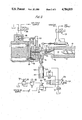
- FIG. 2 is, in part, a cross-sectional view taken along line 2--2 of FIG. 1 of the injection system of the present invention and including, diagrammatically, the operating fluid system;
- FIG. 3 is a sectional view taken along line 4--4 of FIG. 2 showing the accumulator piston at the full inward position;
- FIG. 4 is the same as FIG. 3 showing the accumulator piston in the retraction position
- FIG. 5 is a timing sequence diagram for the injection molding cycle.
- Attached to barrel 12 is heated nozzle body 16 having a passage 18 and a rotary shut-off valve 20 actuated by fluid motor 22 controlled by a solenoid operated air valve 24.
- Downstream of the rotary valve 20 is located accumulator chamber 28.
- the accumulator 28 is closed by cylinder head plug 30.
- Piston 26 and head plug 30 are shaped to form a passageway 32 when piston and head plug are in contact as shown in FIG. 3.
- the continuing transfer passage 18 conducts the plastic to the hot runner manifold via passage 36 to the valve chamber 38.
- Mold gate valve 40 controls the plastic flow into the mold cavity 42.
- the mold gate valve 40 is actuated by plate 44 and hydraulic cylinder 46 controlled by a solenoid operated valve 48.
- Accumulator piston 26 is connected to and driven by the piston 52 operated by a hydraulic cylinder 50.
- the accumulator piston 26 outward travel velocity is controlled by the flow valve 54.
- Directional control valve 56 operated by solenoid 58 directs piston 26 inward for the purge cycle and the hold pressure cycle.
- Solenoid 60 directs piston 26 outward during the de-compression cycle.
- Pressure reducing valve 62 operates the purge pressure level by adjustment 64.
- Solenoid valve 66 when operated causes the reducing valve 62 to be controlled by pressure release valve 68 using adjustment 70 to set the level for the hold pressure.
- Check valve 72 prevents fluid drain from the system during the accumulator piston refill cycle.
- the assembly operates in accordance with the timing sequence diagram shown in FIG. 5 which demonstrates sequential operation of the assembly.
- the injector screw 10 has plasticized the material in chamber 14. Passages 18 and 36, and chamber 38 are filled with plastic. Mold gate valve 40 is closed.
- the injector screw 10 propels the plastic through the passages into the cavity 42. Simultaneously, the accumulator piston 26 thrusts inward directed by valve 56 and solenoid 58 at a pressure set on reducing valve 62 purging the residual plastic from chamber 28. When the accumulator piston 26 contacts head plug 30, the plastic then flows through passage 32 flushing out residual material.
- solenoid 58 De-energization of solenoid 58 allows directional valve 56 to return to center position which allows plastic to refill the accumulator chamber 28, causing piston 52 to move outward at a rate controlled by flow valve 54.
- the plastic has been expelled from chamber 14, filling accumulator 28 and cavity 42.
- the directional valve 56 operated by solenoid 58 permits the holding pressure to be applied by operation of valve 66 and pressure release valve 68.
- the cavity is now under pressure from both injector screw 10 and accumulator piston 26.
- the rotary shut-off valve 20 is returned to the closed position, allowing the injector screw to rotate and plasticize the next charge.
- the accumulator piston 26 continues to apply the holding pressure on the plastic compensating for volumetric shrinkage within the mold cavity 42 to maintain uniform wall thickness and temperature control of the plastic article.
- directional valve 56 controlled by solenoid 60 retracts pistons 52 and 26, decompressing the plastic in valve chamber 38.
- the mold gate valve 40 is now closed operating against minimum plastic resistance.
- the mold cavity is opened for removal of the article. The injector screw rotation may continue during the mold open period until the plasticizing requirements have been met.
- the assembly permits the accumulator piston to provide the holding pressure while the injection screw rotation is plasticizing the next charge. This allows for longer plasticizing time, producing less material shear and heat due to a lower screw rotation rate with less power required for screw torque.
- the mold cure time is determined by the residual heat of the wall and, therefore, the plastic part must be removed at a precise time from the mold. This time period is not limited or governed by the plasticizing cycle.
- the assembly is beneficial in applications where the part temperature must be controlled to permit the next succeeding operation of the plastic part such as forming and conditioning a parison prearatory to a sequential blow forming cycle.
- Other advantages of the system flow from the overall design including its simplicity of construction and operation.
Abstract
Description
Claims (3)
Priority Applications (1)
| Application Number | Priority Date | Filing Date | Title |
|---|---|---|---|
| US06/620,382 US4784819A (en) | 1982-03-19 | 1984-06-13 | Method of injection molding of plastic parts utilizing an accumlator chamber and valve chamber between the plasticizer and mold |
Applications Claiming Priority (2)
| Application Number | Priority Date | Filing Date | Title |
|---|---|---|---|
| US36004882A | 1982-03-19 | 1982-03-19 | |
| US06/620,382 US4784819A (en) | 1982-03-19 | 1984-06-13 | Method of injection molding of plastic parts utilizing an accumlator chamber and valve chamber between the plasticizer and mold |
Related Parent Applications (1)
| Application Number | Title | Priority Date | Filing Date |
|---|---|---|---|
| US36004882A Continuation | 1982-03-19 | 1982-03-19 |
Publications (1)
| Publication Number | Publication Date |
|---|---|
| US4784819A true US4784819A (en) | 1988-11-15 |
Family
ID=27000730
Family Applications (1)
| Application Number | Title | Priority Date | Filing Date |
|---|---|---|---|
| US06/620,382 Expired - Lifetime US4784819A (en) | 1982-03-19 | 1984-06-13 | Method of injection molding of plastic parts utilizing an accumlator chamber and valve chamber between the plasticizer and mold |
Country Status (1)
| Country | Link |
|---|---|
| US (1) | US4784819A (en) |
Cited By (20)
| Publication number | Priority date | Publication date | Assignee | Title |
|---|---|---|---|---|
| WO1992003274A1 (en) * | 1990-08-27 | 1992-03-05 | E.I. Du Pont De Nemours And Company | Direct fabrication |
| US5114658A (en) * | 1990-11-15 | 1992-05-19 | E. I. Du Pont De Nemours And Company | One step preparation and fabrication of partially grafted flexible thermoplastic compositions |
| US5118273A (en) * | 1989-12-07 | 1992-06-02 | Japan Crown Cork Co., Ltd. | Compression molding apparatus |
| US5123833A (en) * | 1991-04-01 | 1992-06-23 | Parker John C | Fast cycle plasticator/injector unit for molding machines |
| US5130076A (en) * | 1990-08-27 | 1992-07-14 | E. I. Du Pont De Nemours And Company | Direct fabrication |
| US5205969A (en) * | 1988-05-25 | 1993-04-27 | Signicast Corporation | Process for distributing a semi-solid wax to an injection press |
| US5219512A (en) * | 1988-10-13 | 1993-06-15 | Seiki Corporation | Improved pressure-holding chamber type injection molding process and apparatus for injection molding of products |
| US5221507A (en) * | 1990-04-24 | 1993-06-22 | Devtech Labs, Inc. | Process for coinjection molding of preforms for multi-layer containers |
| US5248460A (en) * | 1989-10-12 | 1993-09-28 | Seiki Corporation | Pressure-holding chamber type injection molding process and apparatus |
| US5499916A (en) * | 1994-10-28 | 1996-03-19 | Husky Injection Molding Systems Ltd. | Rotary actuated gate valve |
| WO1999000237A1 (en) * | 1997-06-26 | 1999-01-07 | Vicfam Plastics Pty. Ltd. | Injection moulding of large plastic components |
| US6017210A (en) * | 1995-09-27 | 2000-01-25 | Nissei Plastics Industrial Co., Ltd. | Apparatus for dwelling in injection molding |
| US6045736A (en) * | 1994-05-18 | 2000-04-04 | Aisa Automation Industrielle S.A. | Method for producing a molded plastic article |
| AU740037B2 (en) * | 1997-06-26 | 2001-10-25 | Vicfam Plastics Pty. Ltd. | Injection moulding of large plastic components |
| US6382946B1 (en) | 1998-04-01 | 2002-05-07 | Dtl Technology Limited Partnership | Molding multi-layered articles using coinjection techniques |
| US20070052124A1 (en) * | 2005-09-02 | 2007-03-08 | Park Chul B | Apparatus and method for advanced structural foam molding |
| US20070194474A1 (en) * | 2006-02-23 | 2007-08-23 | Nagy Peter S | Injection molding press |
| US20080224353A1 (en) * | 2007-03-14 | 2008-09-18 | Husky Injection Molding Systems Ltd. | Hydraulic Valve of Molding System |
| US8708683B2 (en) | 2009-12-31 | 2014-04-29 | Husky Injection Molding Systems Ltd. | Mold-runner system having independently controllable shooting-pot assemblies |
| US20150332814A1 (en) * | 2012-10-17 | 2015-11-19 | Samp S.P.A. Con Unico Socio | Apparatus for the production of an electric conductor provided with at least one coating layer of plastic material |
Citations (6)
| Publication number | Priority date | Publication date | Assignee | Title |
|---|---|---|---|---|
| US28721A (en) * | 1860-06-12 | whitaker | ||
| GB912695A (en) * | 1960-01-07 | 1962-12-12 | Fischer Ag Georg | Improvements in or relating to methods of and devices for maintaining the follow-up pressure in injection moulds |
| US3268636A (en) * | 1963-07-01 | 1966-08-23 | Union Carbide Corp | Method and apparatus for injection molding foamed plastic articles |
| JPS5337763A (en) * | 1976-09-20 | 1978-04-07 | Asahi Dow Ltd | Injection molding machine |
| US4124308A (en) * | 1977-06-21 | 1978-11-07 | Beloit Corporation | Sequential co-injection unit adapted for structural foam molding |
| US4342717A (en) * | 1975-10-31 | 1982-08-03 | Hpm Corporation | Injection moulding method and apparatus with mould runner reservoir and shot extension |
-
1984
- 1984-06-13 US US06/620,382 patent/US4784819A/en not_active Expired - Lifetime
Patent Citations (6)
| Publication number | Priority date | Publication date | Assignee | Title |
|---|---|---|---|---|
| US28721A (en) * | 1860-06-12 | whitaker | ||
| GB912695A (en) * | 1960-01-07 | 1962-12-12 | Fischer Ag Georg | Improvements in or relating to methods of and devices for maintaining the follow-up pressure in injection moulds |
| US3268636A (en) * | 1963-07-01 | 1966-08-23 | Union Carbide Corp | Method and apparatus for injection molding foamed plastic articles |
| US4342717A (en) * | 1975-10-31 | 1982-08-03 | Hpm Corporation | Injection moulding method and apparatus with mould runner reservoir and shot extension |
| JPS5337763A (en) * | 1976-09-20 | 1978-04-07 | Asahi Dow Ltd | Injection molding machine |
| US4124308A (en) * | 1977-06-21 | 1978-11-07 | Beloit Corporation | Sequential co-injection unit adapted for structural foam molding |
Cited By (23)
| Publication number | Priority date | Publication date | Assignee | Title |
|---|---|---|---|---|
| US5205969A (en) * | 1988-05-25 | 1993-04-27 | Signicast Corporation | Process for distributing a semi-solid wax to an injection press |
| US5219512A (en) * | 1988-10-13 | 1993-06-15 | Seiki Corporation | Improved pressure-holding chamber type injection molding process and apparatus for injection molding of products |
| US5248460A (en) * | 1989-10-12 | 1993-09-28 | Seiki Corporation | Pressure-holding chamber type injection molding process and apparatus |
| US5118273A (en) * | 1989-12-07 | 1992-06-02 | Japan Crown Cork Co., Ltd. | Compression molding apparatus |
| US5221507A (en) * | 1990-04-24 | 1993-06-22 | Devtech Labs, Inc. | Process for coinjection molding of preforms for multi-layer containers |
| US5130076A (en) * | 1990-08-27 | 1992-07-14 | E. I. Du Pont De Nemours And Company | Direct fabrication |
| WO1992003274A1 (en) * | 1990-08-27 | 1992-03-05 | E.I. Du Pont De Nemours And Company | Direct fabrication |
| US5114658A (en) * | 1990-11-15 | 1992-05-19 | E. I. Du Pont De Nemours And Company | One step preparation and fabrication of partially grafted flexible thermoplastic compositions |
| WO1992008596A1 (en) * | 1990-11-15 | 1992-05-29 | E.I. Du Pont De Nemours And Company | One step preparation and fabrication of partially grafted flexible thermoplastic compositions |
| US5123833A (en) * | 1991-04-01 | 1992-06-23 | Parker John C | Fast cycle plasticator/injector unit for molding machines |
| US6045736A (en) * | 1994-05-18 | 2000-04-04 | Aisa Automation Industrielle S.A. | Method for producing a molded plastic article |
| US5499916A (en) * | 1994-10-28 | 1996-03-19 | Husky Injection Molding Systems Ltd. | Rotary actuated gate valve |
| US6017210A (en) * | 1995-09-27 | 2000-01-25 | Nissei Plastics Industrial Co., Ltd. | Apparatus for dwelling in injection molding |
| WO1999000237A1 (en) * | 1997-06-26 | 1999-01-07 | Vicfam Plastics Pty. Ltd. | Injection moulding of large plastic components |
| AU740037B2 (en) * | 1997-06-26 | 2001-10-25 | Vicfam Plastics Pty. Ltd. | Injection moulding of large plastic components |
| US6464910B1 (en) | 1997-06-26 | 2002-10-15 | Vicfam Plastics Pty Ltd. | Injection moulding of large plastic components |
| US6382946B1 (en) | 1998-04-01 | 2002-05-07 | Dtl Technology Limited Partnership | Molding multi-layered articles using coinjection techniques |
| US20070052124A1 (en) * | 2005-09-02 | 2007-03-08 | Park Chul B | Apparatus and method for advanced structural foam molding |
| US20070194474A1 (en) * | 2006-02-23 | 2007-08-23 | Nagy Peter S | Injection molding press |
| US20080224353A1 (en) * | 2007-03-14 | 2008-09-18 | Husky Injection Molding Systems Ltd. | Hydraulic Valve of Molding System |
| US8708683B2 (en) | 2009-12-31 | 2014-04-29 | Husky Injection Molding Systems Ltd. | Mold-runner system having independently controllable shooting-pot assemblies |
| US20150332814A1 (en) * | 2012-10-17 | 2015-11-19 | Samp S.P.A. Con Unico Socio | Apparatus for the production of an electric conductor provided with at least one coating layer of plastic material |
| US10056173B2 (en) * | 2012-10-17 | 2018-08-21 | Samp S.P.A. Con Unico Socio | Apparatus for extruding a coating around an electric conductor |
Similar Documents
| Publication | Publication Date | Title |
|---|---|---|
| US4784819A (en) | Method of injection molding of plastic parts utilizing an accumlator chamber and valve chamber between the plasticizer and mold | |
| US4701292A (en) | Method for pressure molding objects of different resins | |
| CA1077217A (en) | Method of manufacturing an object in plastics material, apparatus for carrying out the method and object obtained thereby | |
| US4095931A (en) | Injection molding machine and method | |
| US8021587B2 (en) | Method and apparatus for delivering sequential shots to multiple cavities to form multilayer articles | |
| JP6080611B2 (en) | Method for producing foamable injection-molded body and injection device therefor | |
| US3594463A (en) | Process for injection-blow molding hollow articles | |
| JPH11320631A (en) | Operational method of two-stage injection molding machine, plasticization of material in two-stage injection molding machine, and method and system for transferring melt | |
| US5766654A (en) | Apparatus for improving knit line strength in polymeric materials | |
| US6953546B2 (en) | Plastic expulsion process for forming hollow tubular products | |
| JP2008513248A (en) | Plastic product manufacturing apparatus and manufacturing method | |
| GB2116903A (en) | Injection mold assembly | |
| KR20040023808A (en) | Process and apparatus for injection moulding | |
| US3516123A (en) | Injection molding machine | |
| US4342717A (en) | Injection moulding method and apparatus with mould runner reservoir and shot extension | |
| US4256689A (en) | Injection moulding method and apparatus with mould runner reservoir and shot extension | |
| WO2009044142A1 (en) | Injection compression moulding apparatus and injection compression moulding method | |
| JPH07144336A (en) | Method for injection molding thermoplastic synthetic resin material molded piece and mold for conducting the method | |
| JP3174954B2 (en) | Plastic injection molding method and apparatus utilizing a fluid compression unit | |
| CA1279455C (en) | Injection molding press | |
| CA3119151C (en) | Injection method and injection apparatus for molten resin, and injection stretch blow molding machine using injection apparatus | |
| CA2714344C (en) | Compression injection moulding method and device for preforms | |
| JP4028683B2 (en) | Injection molding method and injection molding machine | |
| JP3615650B2 (en) | Gas assist injection molding method and gas assist injection molding apparatus | |
| US6531087B1 (en) | Coupled fluid injection with same power source |
Legal Events
| Date | Code | Title | Description |
|---|---|---|---|
| AS | Assignment |
Owner name: FEDDERS MACHINE & TOOL CO., INC., 23 PAGE ROAD, LO Free format text: ASSIGNMENT OF ASSIGNORS INTEREST.;ASSIGNOR:EMHART INDUSTRIES, INC.;REEL/FRAME:004852/0243 Effective date: 19880323 Owner name: FEDDERS MACHINE & TOOL CO., INC., NEW HAMPSHIRE Free format text: ASSIGNMENT OF ASSIGNORS INTEREST;ASSIGNOR:EMHART INDUSTRIES, INC.;REEL/FRAME:004852/0243 Effective date: 19880323 |
|
| STCF | Information on status: patent grant |
Free format text: PATENTED CASE |
|
| FEPP | Fee payment procedure |
Free format text: PAYOR NUMBER ASSIGNED (ORIGINAL EVENT CODE: ASPN); ENTITY STATUS OF PATENT OWNER: SMALL ENTITY |
|
| FPAY | Fee payment |
Year of fee payment: 4 |
|
| FEPP | Fee payment procedure |
Free format text: PAYER NUMBER DE-ASSIGNED (ORIGINAL EVENT CODE: RMPN); ENTITY STATUS OF PATENT OWNER: SMALL ENTITY Free format text: PAYOR NUMBER ASSIGNED (ORIGINAL EVENT CODE: ASPN); ENTITY STATUS OF PATENT OWNER: SMALL ENTITY |
|
| FPAY | Fee payment |
Year of fee payment: 8 |
|
| FEPP | Fee payment procedure |
Free format text: PAYER NUMBER DE-ASSIGNED (ORIGINAL EVENT CODE: RMPN); ENTITY STATUS OF PATENT OWNER: SMALL ENTITY |
|
| FPAY | Fee payment |
Year of fee payment: 12 |
|
| SULP | Surcharge for late payment |