US4783632A - Multi-arm frequency sweep generator - Google Patents
Multi-arm frequency sweep generator Download PDFInfo
- Publication number
- US4783632A US4783632A US06/881,742 US88174286A US4783632A US 4783632 A US4783632 A US 4783632A US 88174286 A US88174286 A US 88174286A US 4783632 A US4783632 A US 4783632A
- Authority
- US
- United States
- Prior art keywords
- frequency
- frequency sweep
- sweeps
- sweep
- corrected
- Prior art date
- Legal status (The legal status is an assumption and is not a legal conclusion. Google has not performed a legal analysis and makes no representation as to the accuracy of the status listed.)
- Expired - Lifetime
Links
- 239000006185 dispersion Substances 0.000 claims abstract description 19
- 238000012937 correction Methods 0.000 claims description 13
- 230000001934 delay Effects 0.000 claims description 6
- 238000000034 method Methods 0.000 claims description 6
- 230000006870 function Effects 0.000 description 7
- 230000000694 effects Effects 0.000 description 4
- 230000006835 compression Effects 0.000 description 3
- 238000007906 compression Methods 0.000 description 3
- 238000010897 surface acoustic wave method Methods 0.000 description 3
- 238000004519 manufacturing process Methods 0.000 description 2
- 230000007480 spreading Effects 0.000 description 2
- 238000003892 spreading Methods 0.000 description 2
- 238000013459 approach Methods 0.000 description 1
- 230000008859 change Effects 0.000 description 1
- 238000004891 communication Methods 0.000 description 1
- 239000013078 crystal Substances 0.000 description 1
- 238000011982 device technology Methods 0.000 description 1
- 238000010586 diagram Methods 0.000 description 1
- 238000009826 distribution Methods 0.000 description 1
- 238000005516 engineering process Methods 0.000 description 1
- 238000005530 etching Methods 0.000 description 1
- 238000012986 modification Methods 0.000 description 1
- 230000004048 modification Effects 0.000 description 1
- 230000008450 motivation Effects 0.000 description 1
- 239000010453 quartz Substances 0.000 description 1
- 230000004044 response Effects 0.000 description 1
- VYPSYNLAJGMNEJ-UHFFFAOYSA-N silicon dioxide Inorganic materials O=[Si]=O VYPSYNLAJGMNEJ-UHFFFAOYSA-N 0.000 description 1
- 238000001228 spectrum Methods 0.000 description 1
- 230000001360 synchronised effect Effects 0.000 description 1
- 230000001131 transforming effect Effects 0.000 description 1
Images

Classifications
-
- H—ELECTRICITY
- H03—ELECTRONIC CIRCUITRY
- H03B—GENERATION OF OSCILLATIONS, DIRECTLY OR BY FREQUENCY-CHANGING, BY CIRCUITS EMPLOYING ACTIVE ELEMENTS WHICH OPERATE IN A NON-SWITCHING MANNER; GENERATION OF NOISE BY SUCH CIRCUITS
- H03B23/00—Generation of oscillations periodically swept over a predetermined frequency range
-
- H—ELECTRICITY
- H03—ELECTRONIC CIRCUITRY
- H03B—GENERATION OF OSCILLATIONS, DIRECTLY OR BY FREQUENCY-CHANGING, BY CIRCUITS EMPLOYING ACTIVE ELEMENTS WHICH OPERATE IN A NON-SWITCHING MANNER; GENERATION OF NOISE BY SUCH CIRCUITS
- H03B2200/00—Indexing scheme relating to details of oscillators covered by H03B
- H03B2200/006—Functional aspects of oscillators
- H03B2200/0092—Measures to linearise or reduce distortion of oscillator characteristics
Definitions
- the present invention relates to frequency sweeps, and, more particularly, to a multi-arm frequency sweep generator operating at radio frequency.
- Frequency sweeps can be generated by time dispersing a pulse as a function of frequency.
- the pulse is selected to have frequency components over the desired output range of the sweep.
- a reflective array compressor is one device used to produce such dispersion.
- the RAC may be manufactured by etching plural slits in a large quartz crystal. The size and placement of the slits determine the dispersion characteristics of the RAC.
- a RAC can be designed to provide a linear or other specific sweep.
- RACs are well-known in the art and are described for example in "The Use of Surface-Elastic Wave Reflection Gratings in Large Time-Bandwidth Pulse Compression Filters", R. C. Williamson et al, I.E.E.E. Transactions on Microwave Theory and Techniques, Vol. MTT-21, No. 4, April, 1973, pp. 195-205.
- a surface acoustic wave (SAW) demodulator can incorporate three or three sets of RACs.
- the input to the demodulator can be a frequency division multiple access (FDMA) signal.
- FDMA frequency division multiple access
- a first or input RAC time-staggers the individual frequency bands that make up the multiplexed signal.
- a second frequency sweep RAC converts pulses, synchronized to the input bit periods, to sweeps. The sweeps are combined with the staggered frequency channels to produce a series of sweeps.
- a third or output RAC compresses these sweeps into pulses which represent the time division multiplexed (TDM) decoding of the FDMA input.
- TDM time division multiplexed
- RACs While RACs perform quickly and reliably, they are difficult to manufacture precisely.
- a RAC designed to produce a linear frequency sweep, for example, will generally have some characteristic non-linearities. The cost of manufacturing each RAC typically prohibits large scale rejection of deviating devices.
- the characteristics of a RAC can change due to temperature. For RACs to be used in environments such as space with temperature extremes, it is desirable to be able to calibrate a RAC to maintain linearity.
- an error signal can be obtained which when zeroed indicates a linear frequency sweep. More specifically, a sweep can be applied to a known input signal, and the result compared to the expected output. In the SAW demodulator described above, a constant known input should produce a series of pulses with very little spreading. Any spreading can be analyzed as a function of frequency to identify points of non-linearity in the frequency sweep and allow for correction.
- successive sweep triggering pulses are demultiplexed and distributed among multiple arms, each arm having a RAC and a correcting means, advantageously, a complex multiplying digital-to-analog converter (MDAC).
- MDAC complex multiplying digital-to-analog converter
- the corrected sweeps are summed.
- a second RAC or other sweep compressor means determines adjusts the final slope of the sweeps.
- the compressor RAC can advantageously operate in opposition to the dispersion RACs.
- the dispersion RACs can generate sweeps with slopes less than that desired in the output sweeps.
- the greater slopes of the intermediate sweeps provide for ready correction by the MDACs.
- the intermediate sweep slopes can be increased by the compressor RAC to the desired level.
- the resulting sweeps can be overlapping or non-overlapping, as desired.
- a series of accurate calibrated sweeps can be generated at a high repetition rate over a wide range of slopes.
- FIG. 1 is a block diagram of a many-arm frequency sweep generator in accordance with the present invention.
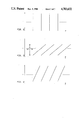
- FIG. 2 is a frequency-time waveform chart of the output of an impulser of the sweep generator of FIG. 1.
- FIG. 3 is a frequency-time waveform chart of an intermediate sweep series of the frequency sweep generator of FIG. 1.
- a many-arm frequency sweep generator 10, illustrated in FIG. 1, provides a series of sweeps such as those shown in FIG. 4.
- the sweep generator 10 includes an impulser 12 or other pulse source, a conventional multiplexer such as a Fairchild chip No. 54F/74F151A 14 or other pulse distribution means for distributing 25 pulses among the multiple arms of the many-arm frequency sweep generator 10.
- Each arm includes a RAC 16, serving as a pulse-dispersion means, and a complex MDAC 18 serving as a correction means.
- the sweep outputs of the multi-arms are summed in a conventional demultiplexer 20 such as a Fairchild chip No. 54F/74F138.
- the summed intermediate sweeps are processed by a compressor RAC 22 or other sweep compression means means to provide the desired output.
- the impulser 12 generates pulses in response to system timing signals, indicated at 30.
- the output of the impulser 12 is shown in FIG. 2.
- Each pulse includes frequency components throughout the bandwidths of the dispersion RACs 16 and the compressor RAC 22. Pulse components outside these bandwidths are effectively filtered out by the RACs.
- the multiplexer 14 serves to distribute successive pulses to respective dispersion RACs 16.
- Each dispersion RAC 16 disperses its input pulse into a sweep of frequency as a function of time.
- the illustrated dispersion RACs 16 are down-chirp RACs, which means they delay lower frequency components of a pulse more than the higher frequency components.
- the effect of an illustrated down-chirp dispersion RAC 16 is indicated by the slope of any individual sweep in FIG. 3, which illustrates the summed output of the multiplexer 20.
- the illustrated compressor RAC 22 is an up-chirp RAC in that it delays higher frequency signals more than lower frequency signals. Its effect is opposed to and relatively less than that of the dispersion RACs 16 so that the latter's effect is partially offset.
- the output of the many-arm frequency sweep generator 10 is a series of non-overlapping frequency sweeps, as illustrated in FIG. 4. However, an overlapping output is provided for by a lesser compression or a higher repetition rate.
- MDACs multiplying digital-to-analog converter
- the illustrated MDACs 18 are designed to correct for nonlinearities or other distortions in the output of the sweep generator by transforming the intermediate sweep according to a predetermined function.
- each complex MDAC effectively divides each sweep into a multitude of time-based segments, and multiplies each such segment by a respective predetermined complex number.
- the effect of the complex multiplication is to adjust the amplitude and phase of each sweep segment in accordance with a predetermined correction function.
- the function is selected to correct actual distortions introduced by the respective dispersion RAC and to cause predistortions to compensate for distortions to be introduced by the compressor RAC.
- MDAC performance can be limited by throughput and the necessity of synchronizing with the sweep to be corrected. If a sweep is of too short duration, the performance parameters of the MDAC can be exceeded. In other words, corrections might be applied to the wrong segments of the sweep.
- the illustrated embodiment provides an intermediate sweep of duration within the performance parameters of the MDACs 18. After the correction is applied, the desired high output slope is provided by the compressor RAC 22.
- a correctable frequency sweep generator with enhanced capability for producing frequency sweeps with steep slopes and at high repetition rates.
- Many modifications and variations of the present invention are contemplated, including different sweep forms, pulse sources, pulse distributing means, dispersion means, and correcting means. Therefore, the present invention is defined only by the scope of the following claims.
Landscapes
- Stabilization Of Oscillater, Synchronisation, Frequency Synthesizers (AREA)
Abstract
Description
Claims (7)
Priority Applications (1)
| Application Number | Priority Date | Filing Date | Title |
|---|---|---|---|
| US06/881,742 US4783632A (en) | 1986-07-03 | 1986-07-03 | Multi-arm frequency sweep generator |
Applications Claiming Priority (1)
| Application Number | Priority Date | Filing Date | Title |
|---|---|---|---|
| US06/881,742 US4783632A (en) | 1986-07-03 | 1986-07-03 | Multi-arm frequency sweep generator |
Publications (1)
| Publication Number | Publication Date |
|---|---|
| US4783632A true US4783632A (en) | 1988-11-08 |
Family
ID=25379112
Family Applications (1)
| Application Number | Title | Priority Date | Filing Date |
|---|---|---|---|
| US06/881,742 Expired - Lifetime US4783632A (en) | 1986-07-03 | 1986-07-03 | Multi-arm frequency sweep generator |
Country Status (1)
| Country | Link |
|---|---|
| US (1) | US4783632A (en) |
Cited By (5)
| Publication number | Priority date | Publication date | Assignee | Title |
|---|---|---|---|---|
| EP0528565A2 (en) * | 1991-08-14 | 1993-02-24 | Matra Marconi Space Uk Limited | Digital chirp generator systems |
| US5278567A (en) * | 1991-11-25 | 1994-01-11 | Hughes Aircraft Company | Post detection integration method and apparatus for pulse compression radar utilizing surface acoustic wave (SAW) matched filters |
| US5757311A (en) * | 1995-09-20 | 1998-05-26 | The Boeing Company | Delayed frequency sweep for FMCW radar |
| WO2014201795A1 (en) * | 2013-06-21 | 2014-12-24 | 武汉大学 | Method for generating and compressing multi-sweep-frequency radar signals |
| US11460540B2 (en) * | 2016-04-01 | 2022-10-04 | Texas Instruments Incorporated | Dynamic IQ mismatch correction in FMCW radar |
Citations (5)
| Publication number | Priority date | Publication date | Assignee | Title |
|---|---|---|---|---|
| US3579117A (en) * | 1968-09-27 | 1971-05-18 | Bell Telephone Labor Inc | Waveform generator |
| US3639842A (en) * | 1968-10-17 | 1972-02-01 | Gen Dynamics Corp | Data transmission system for directly generating vestigial sideband signals |
| US4197540A (en) * | 1977-04-27 | 1980-04-08 | Hughes Aircraft Company | Simultaneous transmit and receive radar subsystem |
| US4359736A (en) * | 1980-11-24 | 1982-11-16 | The United States Of America As Represented By The Secretary Of The Navy | Frequency-phase coding device |
| US4404562A (en) * | 1980-08-25 | 1983-09-13 | The United States Of America As Represented By The Secretary Of The Navy | Low sidelobe linear FM chirp system |
-
1986
- 1986-07-03 US US06/881,742 patent/US4783632A/en not_active Expired - Lifetime
Patent Citations (5)
| Publication number | Priority date | Publication date | Assignee | Title |
|---|---|---|---|---|
| US3579117A (en) * | 1968-09-27 | 1971-05-18 | Bell Telephone Labor Inc | Waveform generator |
| US3639842A (en) * | 1968-10-17 | 1972-02-01 | Gen Dynamics Corp | Data transmission system for directly generating vestigial sideband signals |
| US4197540A (en) * | 1977-04-27 | 1980-04-08 | Hughes Aircraft Company | Simultaneous transmit and receive radar subsystem |
| US4404562A (en) * | 1980-08-25 | 1983-09-13 | The United States Of America As Represented By The Secretary Of The Navy | Low sidelobe linear FM chirp system |
| US4359736A (en) * | 1980-11-24 | 1982-11-16 | The United States Of America As Represented By The Secretary Of The Navy | Frequency-phase coding device |
Non-Patent Citations (2)
| Title |
|---|
| R. C. Williamson and H. I. Smith, "The Use of Surface-Elastic-Wave Reflection Gratings in Large Time-Bandwidth Pulse-Compression Filters," I.E.E.E. Transactions on Microwave Theory and Techniques, vol. MTT-21, No. 4, Apr. 1973, pp. 195-205. |
| R. C. Williamson and H. I. Smith, The Use of Surface Elastic Wave Reflection Gratings in Large Time Bandwidth Pulse Compression Filters, I.E.E.E. Transactions on Microwave Theory and Techniques, vol. MTT 21, No. 4, Apr. 1973, pp. 195 205. * |
Cited By (6)
| Publication number | Priority date | Publication date | Assignee | Title |
|---|---|---|---|---|
| EP0528565A2 (en) * | 1991-08-14 | 1993-02-24 | Matra Marconi Space Uk Limited | Digital chirp generator systems |
| EP0528565A3 (en) * | 1991-08-14 | 1993-06-30 | British Aerospace Space And Communications Limited | Digital chirp generator systems |
| US5278567A (en) * | 1991-11-25 | 1994-01-11 | Hughes Aircraft Company | Post detection integration method and apparatus for pulse compression radar utilizing surface acoustic wave (SAW) matched filters |
| US5757311A (en) * | 1995-09-20 | 1998-05-26 | The Boeing Company | Delayed frequency sweep for FMCW radar |
| WO2014201795A1 (en) * | 2013-06-21 | 2014-12-24 | 武汉大学 | Method for generating and compressing multi-sweep-frequency radar signals |
| US11460540B2 (en) * | 2016-04-01 | 2022-10-04 | Texas Instruments Incorporated | Dynamic IQ mismatch correction in FMCW radar |
Similar Documents
| Publication | Publication Date | Title |
|---|---|---|
| US4652816A (en) | Calibrated radio frequency analog spectrum analyzer | |
| KR101006298B1 (en) | Digital time alignment in a polar modulator | |
| US5239299A (en) | Digital equalization of time interleaved analog to digital converters | |
| US7193544B1 (en) | Parallel, adaptive delta sigma ADC | |
| US4342119A (en) | Multi-tone jammer | |
| JP3909102B2 (en) | RF power measuring device | |
| US4038612A (en) | Swept oscillator automatic linearizer | |
| US8406718B2 (en) | Method for implementing continuous radio frequency (RF) alignment in advanced electronic warfare (EW) signal stimulation systems | |
| US4843390A (en) | Oversampled A/D converter having digital error correction | |
| US4783632A (en) | Multi-arm frequency sweep generator | |
| US4646035A (en) | High precision tunable oscillator and radar equipped with same | |
| US6914935B2 (en) | Fractional N synthesizer with reduced fractionalization spurs | |
| US4747095A (en) | Saw demodulator employing corrective feedback timing | |
| JPH0566269A (en) | Method and apparatus for linearizing sweeping- frequency radar | |
| US5038344A (en) | FDM-TDM transforming device | |
| US4931749A (en) | Phase locked loop sweep frequency synthesizer | |
| US7425908B2 (en) | Method of generating a digital signal that is representative of match errors in an analog digital conversion system with the time interleaving, and an analog digital converter with time interleaving using same | |
| US20020014983A1 (en) | Digital ramp generator with output power level controller | |
| RU175192U1 (en) | VHF RADIO CHANNEL SIMULATOR | |
| US4890055A (en) | Compensated chirp fourier transformer | |
| US4667151A (en) | Calibrated radio frequency sweep | |
| US5214396A (en) | Method and apparatus for providing a biphase modulated signal having flat envelope characteristics without a direct current component | |
| US4396894A (en) | Digital noise generating apparatus | |
| US4679161A (en) | Calibrated overlapping frequency sweep | |
| Molina et al. | Generation of optimum excitation waveforms for mobile radio channel sounding |
Legal Events
| Date | Code | Title | Description |
|---|---|---|---|
| AS | Assignment |
Owner name: HUGHES AIRCRAFT COMPANY, LOS ANGELES, CA. A CORP. Free format text: ASSIGNMENT OF ASSIGNORS INTEREST.;ASSIGNOR:CROOKSHANKS, REX J.;REEL/FRAME:004581/0967 Effective date: 19860627 Owner name: HUGHES AIRCRAFT COMPANY,CALIFORNIA Free format text: ASSIGNMENT OF ASSIGNORS INTEREST;ASSIGNOR:CROOKSHANKS, REX J.;REEL/FRAME:004581/0967 Effective date: 19860627 |
|
| STCF | Information on status: patent grant |
Free format text: PATENTED CASE |
|
| REMI | Maintenance fee reminder mailed | ||
| FPAY | Fee payment |
Year of fee payment: 4 |
|
| SULP | Surcharge for late payment | ||
| FEPP | Fee payment procedure |
Free format text: PAYOR NUMBER ASSIGNED (ORIGINAL EVENT CODE: ASPN); ENTITY STATUS OF PATENT OWNER: LARGE ENTITY |
|
| FPAY | Fee payment |
Year of fee payment: 8 |
|
| AS | Assignment |
Owner name: HUGHES ELECTRONICS CORPORATION, CALIFORNIA Free format text: ASSIGNMENT OF ASSIGNORS INTEREST;ASSIGNOR:HE HOLDINGS INC., HUGHES ELECTRONICS, FORMERLY KNOWN AS HUGHES AIRCRAFT COMPANY;REEL/FRAME:009123/0473 Effective date: 19971216 |
|
| FPAY | Fee payment |
Year of fee payment: 12 |