US478317A - Injector - Google Patents
Injector Download PDFInfo
- Publication number
- US478317A US478317A US478317DA US478317A US 478317 A US478317 A US 478317A US 478317D A US478317D A US 478317DA US 478317 A US478317 A US 478317A
- Authority
- US
- United States
- Prior art keywords
- casing
- cone
- section
- combining
- injector
- Prior art date
- Legal status (The legal status is an assumption and is not a legal conclusion. Google has not performed a legal analysis and makes no representation as to the accuracy of the status listed.)
- Expired - Lifetime
Links
- 238000010276 construction Methods 0.000 description 3
- 230000004048 modification Effects 0.000 description 2
- 238000012986 modification Methods 0.000 description 2
- 241000239290 Araneae Species 0.000 description 1
Images
Classifications
-
- F—MECHANICAL ENGINEERING; LIGHTING; HEATING; WEAPONS; BLASTING
- F04—POSITIVE - DISPLACEMENT MACHINES FOR LIQUIDS; PUMPS FOR LIQUIDS OR ELASTIC FLUIDS
- F04F—PUMPING OF FLUID BY DIRECT CONTACT OF ANOTHER FLUID OR BY USING INERTIA OF FLUID TO BE PUMPED; SIPHONS
- F04F5/00—Jet pumps, i.e. devices in which flow is induced by pressure drop caused by velocity of another fluid flow
- F04F5/44—Component parts, details, or accessories not provided for in, or of interest apart from, groups F04F5/02 - F04F5/42
- F04F5/46—Arrangements of nozzles
- F04F5/461—Adjustable nozzles
Definitions
- the construction of the combining-cone is such that the inner section, or that one which is attached to the casing, could only be inserted and removed at the receiving end of the casing, or, in other words, at that end where the steam and waterinlets are located, so that in inserting and removing the entire combining-cone both ends of the casing have to be opened.
- My present invention has for its object to provide a sectional combining-cone which may be inserted and removed as a whole at the delivering end of the casing, so that when it is necessary to insert or remove any part of the cone or the whole only one end of the casing will require to be opened, the portion of the combining-cone subject to the greatest wear being independently removable, as in the patent above referred to.
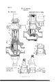
- Figure l represents a longitudinal section of an injector provided with my improvements.
- Fig. 2 represents a elevation.
- Fig'. 3 represents the two parts or sections of the combiningcone removed from the casing, one of said parts being shown in section and the other in Figs. V4c, 5, and 6 represent other modifications hereinafter referred to.
- a represents the casing of the injector, having the steam-cone b, steaminlet d, water-inlet e, the combining-cone f, and the delivery-cone g, said parts being, eX- cept in the particulars hereinafter specified, of the same constructiorras thatshown in Letters Patent N o.
- the combining-cone being made in two sections 2 3, as in said patent, the section 2 including the larger and inner en d of the combining-cone and bearing on the casing a, while the section 3 is externally screw-threaded at its outer end for engagement with the delivery-tube g, the latter being secured to a nut or connecting end t', detachably secured to the delivering end of the casing, all as shown in the patentabovevreferred to.
- FIG. 5 I show the stop-as a spider made in a separate piece from the casing and comprising a ring 5, adapted to bear against a shoulder on the steam-cone, and a series of IOO arms 6, projecting from said ring toward the delivering end of the casing, the outer ends of said arms being arranged to bear on one end of the section 2, as shown more clearly in Fig. 6.
- the section 2 having an internal tapered recess at one end7 while the corresponding end of the section 3 is externally tapered to lit said recess.
- the combination of the casing, the combining-cone, and a seat or stop in said casing adapted to prevent the movement of the combining-cone toward the steam and bear on the said seat in the casing, while the other 3 is adapted to be detachably connected to the delivery cone or tube, said section 2 being of such diameter that it may be introduced into the outer or delivering end of the easing and moved toward the receiving end until it is arrested by said stop, whereby all parts of the combining-cone may be inserted and removed at the delivering end of the casing, the outer portion of the said cone being adapted by the sectional construction of the cone to be removed independently of the seated inner portion, as set forth.
Landscapes
- Engineering & Computer Science (AREA)
- Physics & Mathematics (AREA)
- Fluid Mechanics (AREA)
- Mechanical Engineering (AREA)
- General Engineering & Computer Science (AREA)
- Quick-Acting Or Multi-Walled Pipe Joints (AREA)
Description
(Model.)
W. E. DODGE.
INJEOTOR.
Patented July, 1892.
pa, momumo., wAsnmcrun o c UNrrnD STATES' ATENT Harmon.
VALTER E. DODGE, OFVEVERE'TT, ASSIGNOR TO THE NATIONAL TUBE WORKS OOMPANYYOF BOSTON, MASSACHUSETTS.
INJECTOR.
SYECIFICATION forming part of Letters Patent No. 478,317, dated July 5,' 1892. Application fnednmii 9, 1891. serial No. 384,214. (Model.)
To all whom it may concern,.- i
Be it known that I, WALTER E. DODGE, ot Everett, in the county of Middlesex and State of Massachusetts, have invented certain new and useful Improvements in Injectors, ofV
made in two separable sections, one of which was positively connected with the casing of the injector, while the other was connected with a removable nut or connecting end detachably secured to the casing, so that the last-named section could be removed independently of the other section, the object of the invention being` to permit the renewal of that portion of the combining-cone which is subject to the greatest wear without involving the expense of throwing away the entire combining-cone, the other section-viz., the one attached to the casing-being adapted to serve much longer than the removable section. In said patent the construction of the combining-cone is such that the inner section, or that one which is attached to the casing, could only be inserted and removed at the receiving end of the casing, or, in other words, at that end where the steam and waterinlets are located, so that in inserting and removing the entire combining-cone both ends of the casing have to be opened.
My present invention has for its object to provide a sectional combining-cone which may be inserted and removed as a whole at the delivering end of the casing, so that when it is necessary to insert or remove any part of the cone or the whole only one end of the casing will require to be opened, the portion of the combining-cone subject to the greatest wear being independently removable, as in the patent above referred to. A
To this end the invention consists in the improvements which I will now proceed to describe.
In the accompanying drawings, forming a part of this specification, Figure l represents a longitudinal section of an injector provided with my improvements. Fig. 2 represents a elevation.
longitudinal section of a portion of the injector, showing a modification. Fig'. 3 represents the two parts or sections of the combiningcone removed from the casing, one of said parts being shown in section and the other in Figs. V4c, 5, and 6 represent other modifications hereinafter referred to.
The same letters and numerals of reference indicate the sameipart's in all Ithe figures.
In the drawings, a represents the casing of the injector, having the steam-cone b, steaminlet d, water-inlet e, the combining-cone f, and the delivery-cone g, said parts being, eX- cept in the particulars hereinafter specified, of the same constructiorras thatshown in Letters Patent N o. 383,109 above referred to, the combining-cone being made in two sections 2 3, as in said patent, the section 2 including the larger and inner en d of the combining-cone and bearing on the casing a, while the section 3 is externally screw-threaded at its outer end for engagement with the delivery-tube g, the latter being secured to a nut or connecting end t', detachably secured to the delivering end of the casing, all as shown in the patentabovevreferred to.
In carrying out my invention I make the section 2 of the combining-'cone of such diameter that it can be -freely inserted and removed at the delivering end of the casing when the nut 't' is removed therefrom and provide within the casing a stop, which limits the movement of the section 2 toward the receiving end of the casing and permits said section to move from the delivering end to its operative position and supports said section in said position. The said stop is shown in Figs. l and 2 as an inwardly-projecting lip or flange 7c, formed integral with the casing and arranged to bear ou one end of the section 2. In Fig. l Ishow the said stop'as a beveled or tapered seat 7c', formed on the internal surface of the casing, the section 2 being correspondingly beveled or tapered, Sothat its movement toward the receiving end of the casing will be arrested by said seat.
In-Fig. 5 I show the stop-as a spider made in a separate piece from the casing and comprising a ring 5, adapted to bear against a shoulder on the steam-cone, and a series of IOO arms 6, projecting from said ring toward the delivering end of the casing, the outer ends of said arms being arranged to bear on one end of the section 2, as shown more clearly in Fig. 6.
It will be seen that in each of the constrnctions above described the combining-cone as awhole can be inserted in and removed from the delivering end of the casing and has its operative position defined by a stop within the casing, while the sectional construction of said cone enables the part 3, which is subject to the greatest wear and is most liable to become inoperative, to be readily removed without disturbingthe section 2, that bears on the casing.
I prefer to form the meeting ends of the sections 2 3 as shown in the several figures of the drawings, the section 2 having an internal tapered recess at one end7 while the corresponding end of the section 3 is externally tapered to lit said recess.
In an injector, the combination of the casing, the combining-cone, and a seat or stop in said casing adapted to prevent the movement of the combining-cone toward the steam and bear on the said seat in the casing, while the other 3 is adapted to be detachably connected to the delivery cone or tube, said section 2 being of such diameter that it may be introduced into the outer or delivering end of the easing and moved toward the receiving end until it is arrested by said stop, whereby all parts of the combining-cone may be inserted and removed at the delivering end of the casing, the outer portion of the said cone being adapted by the sectional construction of the cone to be removed independently of the seated inner portion, as set forth.
In testimony whereof I have signed my name to this specification, in the presence of two subscribing witnesses, this 5th day of March, A. D. 1891.
VALTER E. DODGE.
Witnesses:
C. F. BROWN, EWING W. IIAMLEN.
Publications (1)
| Publication Number | Publication Date |
|---|---|
| US478317A true US478317A (en) | 1892-07-05 |
Family
ID=2547172
Family Applications (1)
| Application Number | Title | Priority Date | Filing Date |
|---|---|---|---|
| US478317D Expired - Lifetime US478317A (en) | Injector |
Country Status (1)
| Country | Link |
|---|---|
| US (1) | US478317A (en) |
-
0
- US US478317D patent/US478317A/en not_active Expired - Lifetime
Similar Documents
| Publication | Publication Date | Title |
|---|---|---|
| US793103A (en) | Hose-pipe coupling. | |
| US726395A (en) | Valve for gas or vapor burners. | |
| US478317A (en) | Injector | |
| US540218A (en) | Territory | |
| US426512A (en) | Vaporizer | |
| US1022851A (en) | Air coupling-valve. | |
| US331170A (en) | Dlesex | |
| US997147A (en) | Gas-check. | |
| US262069A (en) | Injector | |
| US1057707A (en) | Boiler-tube-cleaner nozzle. | |
| US450885A (en) | Injector | |
| US450935A (en) | Injector | |
| US508096A (en) | Clasp for pencils | |
| US313834A (en) | Gas-burner | |
| US260073A (en) | Silas s | |
| US968559A (en) | Check-valve. | |
| US440803A (en) | Ejector | |
| US857956A (en) | Pipe connection. | |
| US912233A (en) | Pipe or hose coupling. | |
| US147406A (en) | Improvement in hose-couplings | |
| US674833A (en) | Spray-tube for nebulizers. | |
| US1074100A (en) | Detachable gas-fitting. | |
| US606677A (en) | Pipe-coupling | |
| US573788A (en) | Boiler check-valve | |
| US1066318A (en) | Injector. |