US4782353A - Stepping motor-driven sector opening/closing device - Google Patents
Stepping motor-driven sector opening/closing device Download PDFInfo
- Publication number
- US4782353A US4782353A US06/706,127 US70612785A US4782353A US 4782353 A US4782353 A US 4782353A US 70612785 A US70612785 A US 70612785A US 4782353 A US4782353 A US 4782353A
- Authority
- US
- United States
- Prior art keywords
- rotor
- stators
- magnetic pole
- disposed
- sector
- Prior art date
- Legal status (The legal status is an assumption and is not a legal conclusion. Google has not performed a legal analysis and makes no representation as to the accuracy of the status listed.)
- Expired - Lifetime
Links
Images


Classifications
-
- G—PHYSICS
- G03—PHOTOGRAPHY; CINEMATOGRAPHY; ANALOGOUS TECHNIQUES USING WAVES OTHER THAN OPTICAL WAVES; ELECTROGRAPHY; HOLOGRAPHY
- G03B—APPARATUS OR ARRANGEMENTS FOR TAKING PHOTOGRAPHS OR FOR PROJECTING OR VIEWING THEM; APPARATUS OR ARRANGEMENTS EMPLOYING ANALOGOUS TECHNIQUES USING WAVES OTHER THAN OPTICAL WAVES; ACCESSORIES THEREFOR
- G03B9/00—Exposure-making shutters; Diaphragms
- G03B9/08—Shutters
Definitions
- the present invention relates to a sector opening/closing device using a stepping motor in a camera shutter.
- a stepping motor incorporated in an opening/closing device of a camera is desired to have a high efficiency, consume less current and small in size because a battery is used as a power source.
- the stepping motor must be forward/reverse rotatable for effecting sector opening and closing operations, and so it requires at least two sets of coils and stators, thus resulting, according to the prior art, a construction in which each stator and iron core are separated, or a construction in which the stators are overlapped on a plane. Consequently, not only a larger number of components are required but also the support structures for the stator, etc. become more complicated, thus making it difficult to attain reduction in size and thickness.
- the ordinary camera shutter portion is circular in shape and has a centrally formed lens aperture, so it is necessary that the sector opening/closing device is constituted in a doughnut-like space.
- conventional circular or square motor units are disadvantageous in point of space and thus have been inappropriate as sector opening/closing devices in compact cameras.
- the stepping motor is composed of a radially 4-pole magnetized rotor, two U-shaped stators each having a pair of leg portion, each leg portion having a magnetic pole portion formed at the force end thereof in opposed relation to the outer periphery of the rotor, and coils for exciting the stators.
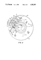
- FIGS. 1 and 2 show construction of a bi-directional stepping motor portion.
- FIGS. 3 and 4 show construction of a wheel train portion and a sector portion.
- FIGS. 5(a) and (b) are diagrams showing output signals from the drive circuit and a section driven by the pulses of FIG. 5(a).
- FIGS. 6(a) through (d), (f) through (i), (e-1) and (e-2) show varying relationships between magnetic field and the magnetic pole portion.
- FIGS. 1 and 2 there is illustrated a construction of a bidirectional stepping motor portion (M) embodying the present invention, in which a rotor 1 comprising a permanent magnet having four radially arranged poles is integrally fixed to a rotor shaft 2.
- a rotor 1 comprising a permanent magnet having four radially arranged poles is integrally fixed to a rotor shaft 2.
- One end of the rotor shaft 2 is rotatably supported by a hole formed in an arc-shaped lower plate 3, while the other end thereof is rotatably supported by a hold formed in an arc-shaped upper plate 4.
- the said one end of the rotor shaft 2 extends through the hole in the lower plate 3, and to the fore end portion thereof is fixed a rotor pinion 5 for transmitting the bidirectional rotation of the rotor 1 to a later-described gear train.
- the numeral 6 denotes a two-pole stator which has a pair of leg portions in a U-shaped one-piece structure. At an end of each leg portion is formed a magnetic pole portion 6a in opposed relation to the outer periphery of the rotor 1.
- the magnetic pole portions 6a of each leg portion are formed in a phase relation of 90° in terms of an angle ( ⁇ ) relative to the center of the rotor 1.
- two stators 6 of the same shape are disposed on the same plane while allowing one magnetic pole portions 6a of the stators to be in proximity to each other so as to be in a phase relation of 45° in terms of an angle ( ⁇ ) relative to the center of the rotor 1.
- the stators 6 are positioned by guide pins 3a formed on the lower plate 3. Further, two coils 7a and 7b for inducing a magnetic field in the magnetic pole portions 6a of the stators are connected to a drive circuit 9 as will be described later.
- the coils 7a and 7b are wound around coil frames 8 and fitted on the leg portions on the side opposite to the proximate magnetic pole portions 6a of the stators 6.
- the lower plate 3 and upper plate 4 are formed by plastic molding, and the lower plate 3 has a retaining pawl 3b for mounting and fixing the upper plate 4, while the upper plate 4 has guide holes 4a for engagement with the guide pins 3a of the lower plate and a lug 4b for engagement with the retaining pawl 3b.
- the two stators 6 with the coils 7a and 7b attached thereto and the rotor 1 are mounted on the lower plate 3 and then covered with the upper plate 4 so that the retaining pawl 3b and the lug 4b come into engagement with each other, whereby the lower and upper plates 3 and 4 and the stators 6 are fixed and the rotor 1 is supported rotatably.
- the plates 3 and 4 comprise an arcuate support for supporting the stepping motor (M).
- FIGS. 3 and 4 there is illustrated a construction of a wheel train portion and a sector portion which are operated by the stepping motor (M), in which a base plate 12 is fixed with bolts to a lens holder plate 11.
- the holder plate 11 and the base plate 12 are centrally formed with a lens aperture (O), and a sector room (R) for housing therein later-described sectors 13 is formed therebetween.
- the numeral 14 denotes a sector driving lever, which is rotatably supported by a rotating shaft 11a formed on the holder plate 11 and which is so supported as not to come off by the lower surface portion of the stepping motor (M).
- the sector driving lever 14 To the sector driving lever 14 is rotatably attached a sector driving wheel 15 as will be described later, and the sector driving lever, and a recess 14b formed in the sector driving lever 14 and a later-described adjusting pin 16 fixed to the sector driving wheel 15 are engaged with each other to restrict the rotation of both (14 and 15). Further, the sector lever 14 is provided with a sector pin 14a which extends through the holder plate 11 and engages a recess 13a formed in each sector 13. The sector 13 is rotatably supported by a pin 11b formed on the holder plate 11. Two such sectors 13 are disposed in symmetrical positions to define an aperture.
- the sector driving wheel 15 attached to the sector driving lever 14 has a toothed portion 15a which is in mesh with a later-described idler wheel 17, an engaging portion 15b adapted to engage a pin 11c formed on the holder plate 11 to restrict rotation, and a pin 15c which is engaged with a spring 19.
- the sector driving wheel 15 is urged in a counterclockwise direction by means of the spring 19.
- the adjusting pin 16 fixed to the sector driving wheel 15 has a diametrical portion engaged with the sector driving wheel 15 and a diametrical portion engaged with the recess 14b of the sector driving lever, both such diametrical portions being eccentric from each other, and it is fixed to the sector driving wheel 15 so as to be rotatable at a predetermined frictional slip torque by caulking or any other suitable means. Therefore, by turning a slotted portion of the adjusting pin 16 with a screw-driver or the like, it is made possible to adjust the phase relation between the toothed portion 15a of the sector driving wheel and the sector pin 14a of the sector driving lever.
- the numeral 17 denotes an idler wheel having a pinion portion 17a which is in mesh with the toothed portion 15a of the sector driving wheel and a toothed portion 17b which is in mesh with the rotor pinion 5.
- the idler wheel 17 is rotatably supported by a rotating shaft 11d formed on the holder plate 11 and so supported as not to come off by the lower surface portion of the stepping motor (M).
- the holder plate 11 is further provided with a post 11e for mounting the stepping motor (M). More specifically, the stepping motor (M) is fixed to the post 11e with a set-screw 18, whereby it becomes possible for the rotor pinion 5 and the idler wheel 17 to engage each other and transmit rotation.
- FIG. 5(a) there are illustrated output signals from the drive circuit 9 for energizing the two coils 7a and 7b to generate a predetermined magnetic field in each magnetic pole portion 6a of the stators.
- the driving signals are two-phase excitation type driving signals of a known bipolar drive in which the coil exciting current is in both plus(+) and minus(-) directions and it flows through the two coils at all times.
- the driving signals are correlated with photometric and distance informations on the object. For example, where the brightness of the object is low, the number of coil exciting pulses is increased, while when the object is bright, the number of such exciting pulse is decreased.
- FIG. 5(b) is an operation diagram of the sector 13 as driven by the pulses of FIG. 5(a). As seen from the operation diagram, the sector 13 controls both the exposure time and the lens aperture.
- the elongated stators 6 are disposed on an arcuate support 3 having an inner arcuate periphery in FIG. 1, and the leg portions having proximate magnetic pole portions of the stators 6 are positioned along the lens aperture (O) side, i.e., along the inner periphery of the support 3, 4 which surrounds part of the lens aperture, while the other leg portions are positioned on the outer peripheral side, with the coils 7a and 7b being mounted on the outer leg portions.
- This arrangement permits the rotor 1 to be disposed at the central part of the stepping motor (M), so that the shutter is not affected by an external magnetic member, and there can be attained advantages in point of coil space and planar arrangement.
- the sector opening/closing device of the invention operates in the following manner.
- release means or photometric means of camera are operated to determine output signals from the drive circuit 9, for example, as in FIG. 5(a) according to information on the object.
- the output signals are applied to the two coils 7a and 7b to effect the following sector opening/closing operations.
- the first pulse is applied to generate such a magnetic field as shown in FIG. 6(b) in the magnetic pole portions 6a of the stators so as to maintain the stationary state of the rotor 1 like shown in FIG. 6(a).
- the rotor 1 does not move while current is not fed, by virtue of the foregoing magnetic coupling force between the rotor and the stator magnetic pole portions 6a, but in the event a large external force or shock is exerted on the camera, the above standstill position will be deflected. This impedes the normal operation of the shutter.
- the first exciting pulse functions to correct the standstill position of the rotor 1 for preventing such inconvenience.
- the same pulse as the first pulse is applied to the coil 7a, while an inverted-current pulse is applied to the coil 7b, whereupon such a magnetic field as shown in FIG. 6(c) is generated, so that the rotor 1 turns 45° clockwise up to its position shown in FIG. 6(d).
- the spring 19 which urges the sector driving wheel 15 in the counterclockwise direction is for preventing variation in the aperture defined by the sectors 13 and the resultant deterioration of the exposure performance which may be caused by the clearance and backlash respectively of rotation support portions and engaging portions such as rotor pinion 5, idler wheel 17 and sector driving wheel 15.
- the spring 19 may be omitted in a low-grade camera not requiring high performance.
- the adjusting pin 16 which connects the sector driving wheel 15 with the sector driving lever 14 by turning it with a screw-driver or the like, there arises a change in phase relation of the sector driving lever 14, thereby causing a change in the amount of overlap of the two sectors 13 before operation and a change in the aperture diameter during the opening operation.
- the pin 16 is used for adjusting the exposure.
- the current is inverted from the fourth to fifth pulse to rotate the rotor 1 in the reverse direction.
- the shutter is programmed so that the timing of such inverted pulse varies according to photometric and distance informations, for example, where the object is bright or in the case of a short-distance photographing using an electronic flash, the pulse inversion is performed in a less pulsed position, while when the object is dark or in the case of a long-distance photographing using an electronic flash, such inversion is allowed to take place in a more pulsed position.
- the stator portion other than the magnetic pole portions can take a relatively free shape provided the magnetic pole portions are held in the foregoing phase relationship. Therefore, where the sector opening/closing device is constituted in a doughnut-like space like this embodiment, not only an arcuate stepping motor but also a rectangular stepping motor can be constituted very easily.
- the stepping motor portion comprises a 4-pole rotor and two U-shaped stators which are arranged planarly, a simpler structure and reduction in thickness can be attained as compared with the prior art.
- a high efficiency small-sized stepping motor can be constituted by using a rare earth magnet as the rotor magnet material, and hence the sector opening/closing device can be constituted in a compact form.
- the device of the present invention is superior in assembling and mass-producing properties as well economy.
Landscapes
- Physics & Mathematics (AREA)
- General Physics & Mathematics (AREA)
- Diaphragms For Cameras (AREA)
- Shutters For Cameras (AREA)
Abstract
Description
Claims (14)
Applications Claiming Priority (4)
| Application Number | Priority Date | Filing Date | Title |
|---|---|---|---|
| JP1984026808U JPH062468Y2 (en) | 1984-02-27 | 1984-02-27 | Small step motor |
| JP59-26808 | 1984-02-27 | ||
| JP59-26804 | 1984-02-27 | ||
| JP2680484U JPS60141682U (en) | 1984-02-27 | 1984-02-27 | Step motor driven sector opening/closing device |
Publications (1)
| Publication Number | Publication Date |
|---|---|
| US4782353A true US4782353A (en) | 1988-11-01 |
Family
ID=26364634
Family Applications (1)
| Application Number | Title | Priority Date | Filing Date |
|---|---|---|---|
| US06/706,127 Expired - Lifetime US4782353A (en) | 1984-02-27 | 1985-02-27 | Stepping motor-driven sector opening/closing device |
Country Status (1)
| Country | Link |
|---|---|
| US (1) | US4782353A (en) |
Cited By (30)
| Publication number | Priority date | Publication date | Assignee | Title |
|---|---|---|---|---|
| US4893142A (en) * | 1987-11-16 | 1990-01-09 | Seikosha Co., Ltd. | Device for activating motor-driven shutter blades |
| US4958099A (en) * | 1987-09-03 | 1990-09-18 | Canon Kabushiki Kaisha | Brushless motor |
| GB2235593A (en) * | 1989-09-01 | 1991-03-06 | Asahi Optical Co Ltd | Mounting a stepping motor on an annular support |
| US5109250A (en) * | 1988-12-16 | 1992-04-28 | Seikosha Co., Ltd. | Program shutter |
| US5302875A (en) * | 1991-04-19 | 1994-04-12 | Eta Sa Fabriques D'ebauches | Electromagnetic motor with two rotation senses particularly intended for a timepiece |
| US5521451A (en) * | 1991-06-06 | 1996-05-28 | Moving Magnet Technologies S.A. | Low-cost stepping or synchronous motor |
| US5945750A (en) * | 1995-02-11 | 1999-08-31 | Trw Fahrzeugelektrik Gmbh & Co. Kg | Stepping motor |
| US5959378A (en) * | 1994-08-10 | 1999-09-28 | Echkhart W. Haller | Electromagnetic, two-phase pulse motor with two rotation directions |
| US5969444A (en) * | 1997-04-28 | 1999-10-19 | Minolta Co., Ltd. | Stepping motor and taking lens barrel for camera incorporating said stepping motor |
| US5999752A (en) * | 1997-06-05 | 1999-12-07 | Minolta Co., Ltd. | Exposure controller for use in a camera |
| US6194797B1 (en) * | 1997-10-29 | 2001-02-27 | Mannesmann Vdo Ag | Method for producing a multipole electric motor, and a multipole electric motor |
| US6404090B1 (en) * | 1995-08-23 | 2002-06-11 | Microsystem Controls Pty Ltd | Apparatus for obtaining certain characteristics of an article |
| US20020190594A1 (en) * | 2000-10-31 | 2002-12-19 | Hiroyasu Numaya | Movable-magnet type meter and meter device using this movable-magnet type meter |
| US20030048033A1 (en) * | 2001-07-23 | 2003-03-13 | Nidec Copal Corporation | Step motor with interpole pair stabilizing rest position |
| US6670731B2 (en) * | 2001-03-23 | 2003-12-30 | Tdk Corporation | Stepping motor |
| US20040178685A1 (en) * | 2003-03-10 | 2004-09-16 | Shotaro Abe | Stepping motor |
| US20060097588A1 (en) * | 2004-11-11 | 2006-05-11 | Denso Corporation | Stepping motor |
| US20060163953A1 (en) * | 2003-06-30 | 2006-07-27 | Seiko Precision Inc. | Step motor |
| US20070018513A1 (en) * | 2003-08-29 | 2007-01-25 | Seiko Precision Inc. | Electromagnetic actuator |
| US20070132322A1 (en) * | 2005-12-10 | 2007-06-14 | Chiang Lee C | Stepper motor having solenoid coils around end portions of stator poles |
| US20070138898A1 (en) * | 2005-12-16 | 2007-06-21 | Promovet S.R.L. | Synchronous motor with permanent-magnet rotor |
| US20080018208A1 (en) * | 2006-07-24 | 2008-01-24 | Roberto Zafferri | Stepping Motor |
| US20080106158A1 (en) * | 2003-06-30 | 2008-05-08 | Seiko Precision Inc. | Step motor |
| US20080224573A1 (en) * | 2007-03-13 | 2008-09-18 | I-Te Chang | Step motor |
| US20090245780A1 (en) * | 2008-03-27 | 2009-10-01 | Kun-Feng Chiang | Shutter device |
| US20100092166A1 (en) * | 2008-04-25 | 2010-04-15 | Seiko Precision Inc. | Blade drive device and optical apparatus |
| US20100314962A1 (en) * | 2009-06-15 | 2010-12-16 | Tamron Co., Ltd. | Three-Phase Brushless DC Motor |
| US20110043067A1 (en) * | 2009-08-21 | 2011-02-24 | Yue Li | Universal motor |
| US20160202666A1 (en) * | 2015-01-14 | 2016-07-14 | Casio Computer Co., Ltd. | Hand-moving mechanism and timepiece |
| US11114919B2 (en) * | 2018-08-01 | 2021-09-07 | Johnson Electric International AG | Actuator |
Citations (17)
| Publication number | Priority date | Publication date | Assignee | Title |
|---|---|---|---|---|
| US1185337A (en) * | 1915-07-13 | 1916-05-30 | Robert H Mccartney | Camera-shutter control. |
| US2970529A (en) * | 1956-01-12 | 1961-02-07 | Optische Ind De Oude Delft Nv | Focal plane shutter |
| US3698300A (en) * | 1969-08-18 | 1972-10-17 | Minolta Camera Kk | Electric shutter mechanism for a camera |
| US3969642A (en) * | 1973-07-17 | 1976-07-13 | Kabushiki Kaisha Suwa Seikosha | Step motor for electronic timepiece |
| US4009866A (en) * | 1974-10-18 | 1977-03-01 | West Electric Company, Ltd. | Exposure control device |
| US4016574A (en) * | 1974-04-23 | 1977-04-05 | West Electric Company, Ltd. | Program-controlled shutter |
| US4057810A (en) * | 1974-08-20 | 1977-11-08 | West Electric Co., Ltd. | Exposure control system |
| US4079390A (en) * | 1974-10-18 | 1978-03-14 | West Electric Co., Ltd. | Aperture setting device for use with exposure control device |
| US4144467A (en) * | 1973-11-30 | 1979-03-13 | Citizen Watch Co., Ltd. | Pulse motor |
| US4218121A (en) * | 1977-11-29 | 1980-08-19 | Konishiroku Photo Industry Co., Ltd. | Automatic aperture driving mechanism |
| US4267472A (en) * | 1977-08-25 | 1981-05-12 | Quarz-Zeit Ag | Single phase stepping motor, particularly for clocks |
| JPS5793330A (en) * | 1980-12-02 | 1982-06-10 | Canon Inc | Electromagnetic driving device of program electromagnetic shutter |
| US4371821A (en) * | 1979-07-06 | 1983-02-01 | Ebauches S.A. | Electromagnetic motor rotatable in either direction |
| JPS5827134A (en) * | 1981-08-10 | 1983-02-17 | Olympus Optical Co Ltd | Lens shutter mechanism for camera |
| JPS5967518A (en) * | 1982-10-09 | 1984-04-17 | Canon Electronics Inc | Driving device of electromagnetically driven shutter |
| US4491751A (en) * | 1981-04-09 | 1985-01-01 | Moskovsky Energetichesky Institut | Single-phase step motor |
| US4518884A (en) * | 1980-04-18 | 1985-05-21 | Centre Technique De L'industrie Horlogere "Cetehor" | Step motor particularly for electronic timepieces |
-
1985
- 1985-02-27 US US06/706,127 patent/US4782353A/en not_active Expired - Lifetime
Patent Citations (17)
| Publication number | Priority date | Publication date | Assignee | Title |
|---|---|---|---|---|
| US1185337A (en) * | 1915-07-13 | 1916-05-30 | Robert H Mccartney | Camera-shutter control. |
| US2970529A (en) * | 1956-01-12 | 1961-02-07 | Optische Ind De Oude Delft Nv | Focal plane shutter |
| US3698300A (en) * | 1969-08-18 | 1972-10-17 | Minolta Camera Kk | Electric shutter mechanism for a camera |
| US3969642A (en) * | 1973-07-17 | 1976-07-13 | Kabushiki Kaisha Suwa Seikosha | Step motor for electronic timepiece |
| US4144467A (en) * | 1973-11-30 | 1979-03-13 | Citizen Watch Co., Ltd. | Pulse motor |
| US4016574A (en) * | 1974-04-23 | 1977-04-05 | West Electric Company, Ltd. | Program-controlled shutter |
| US4057810A (en) * | 1974-08-20 | 1977-11-08 | West Electric Co., Ltd. | Exposure control system |
| US4009866A (en) * | 1974-10-18 | 1977-03-01 | West Electric Company, Ltd. | Exposure control device |
| US4079390A (en) * | 1974-10-18 | 1978-03-14 | West Electric Co., Ltd. | Aperture setting device for use with exposure control device |
| US4267472A (en) * | 1977-08-25 | 1981-05-12 | Quarz-Zeit Ag | Single phase stepping motor, particularly for clocks |
| US4218121A (en) * | 1977-11-29 | 1980-08-19 | Konishiroku Photo Industry Co., Ltd. | Automatic aperture driving mechanism |
| US4371821A (en) * | 1979-07-06 | 1983-02-01 | Ebauches S.A. | Electromagnetic motor rotatable in either direction |
| US4518884A (en) * | 1980-04-18 | 1985-05-21 | Centre Technique De L'industrie Horlogere "Cetehor" | Step motor particularly for electronic timepieces |
| JPS5793330A (en) * | 1980-12-02 | 1982-06-10 | Canon Inc | Electromagnetic driving device of program electromagnetic shutter |
| US4491751A (en) * | 1981-04-09 | 1985-01-01 | Moskovsky Energetichesky Institut | Single-phase step motor |
| JPS5827134A (en) * | 1981-08-10 | 1983-02-17 | Olympus Optical Co Ltd | Lens shutter mechanism for camera |
| JPS5967518A (en) * | 1982-10-09 | 1984-04-17 | Canon Electronics Inc | Driving device of electromagnetically driven shutter |
Cited By (48)
| Publication number | Priority date | Publication date | Assignee | Title |
|---|---|---|---|---|
| US4958099A (en) * | 1987-09-03 | 1990-09-18 | Canon Kabushiki Kaisha | Brushless motor |
| US4893142A (en) * | 1987-11-16 | 1990-01-09 | Seikosha Co., Ltd. | Device for activating motor-driven shutter blades |
| US5109250A (en) * | 1988-12-16 | 1992-04-28 | Seikosha Co., Ltd. | Program shutter |
| GB2235593A (en) * | 1989-09-01 | 1991-03-06 | Asahi Optical Co Ltd | Mounting a stepping motor on an annular support |
| FR2651619A1 (en) * | 1989-09-01 | 1991-03-08 | Asahi Optical Co Ltd | STEPPER MOTOR ASSEMBLY. |
| US5117137A (en) * | 1989-09-01 | 1992-05-26 | Asahi Kogaku Kogyo Kabushiki Kaisha | Stepping motor for use in a camera with multiple shutters |
| US5302875A (en) * | 1991-04-19 | 1994-04-12 | Eta Sa Fabriques D'ebauches | Electromagnetic motor with two rotation senses particularly intended for a timepiece |
| US5521451A (en) * | 1991-06-06 | 1996-05-28 | Moving Magnet Technologies S.A. | Low-cost stepping or synchronous motor |
| US5959378A (en) * | 1994-08-10 | 1999-09-28 | Echkhart W. Haller | Electromagnetic, two-phase pulse motor with two rotation directions |
| US5945750A (en) * | 1995-02-11 | 1999-08-31 | Trw Fahrzeugelektrik Gmbh & Co. Kg | Stepping motor |
| US6404090B1 (en) * | 1995-08-23 | 2002-06-11 | Microsystem Controls Pty Ltd | Apparatus for obtaining certain characteristics of an article |
| US5969444A (en) * | 1997-04-28 | 1999-10-19 | Minolta Co., Ltd. | Stepping motor and taking lens barrel for camera incorporating said stepping motor |
| US5999752A (en) * | 1997-06-05 | 1999-12-07 | Minolta Co., Ltd. | Exposure controller for use in a camera |
| US6194797B1 (en) * | 1997-10-29 | 2001-02-27 | Mannesmann Vdo Ag | Method for producing a multipole electric motor, and a multipole electric motor |
| US20020190594A1 (en) * | 2000-10-31 | 2002-12-19 | Hiroyasu Numaya | Movable-magnet type meter and meter device using this movable-magnet type meter |
| US6727622B2 (en) * | 2000-10-31 | 2004-04-27 | Nippon Seiki Co., Ltd. | Movable-magnet type meter and meter device using this movable-magnet type meter |
| US6670731B2 (en) * | 2001-03-23 | 2003-12-30 | Tdk Corporation | Stepping motor |
| EP1244200A3 (en) * | 2001-03-23 | 2004-03-10 | TDK Corporation | Stepping motor |
| US20030048033A1 (en) * | 2001-07-23 | 2003-03-13 | Nidec Copal Corporation | Step motor with interpole pair stabilizing rest position |
| US6714733B2 (en) | 2001-07-23 | 2004-03-30 | Nidec Copal Corporation | Step motor with interpole pair stabilizing rest position |
| US20040178685A1 (en) * | 2003-03-10 | 2004-09-16 | Shotaro Abe | Stepping motor |
| US6989615B2 (en) * | 2003-03-10 | 2006-01-24 | Calsonic Kansei Corporation | Stepping motor |
| US20080106158A1 (en) * | 2003-06-30 | 2008-05-08 | Seiko Precision Inc. | Step motor |
| US20060163953A1 (en) * | 2003-06-30 | 2006-07-27 | Seiko Precision Inc. | Step motor |
| US7211910B2 (en) * | 2003-06-30 | 2007-05-01 | Seiko Precision Inc. | Step motor |
| US20070018513A1 (en) * | 2003-08-29 | 2007-01-25 | Seiko Precision Inc. | Electromagnetic actuator |
| US7358629B2 (en) * | 2003-08-29 | 2008-04-15 | Seiko Precision Inc. | Electromagnetic actuator |
| US20060097588A1 (en) * | 2004-11-11 | 2006-05-11 | Denso Corporation | Stepping motor |
| US7276825B2 (en) * | 2004-11-11 | 2007-10-02 | Denso Corporation | Stepping motor |
| US20070132322A1 (en) * | 2005-12-10 | 2007-06-14 | Chiang Lee C | Stepper motor having solenoid coils around end portions of stator poles |
| US7372179B2 (en) * | 2005-12-10 | 2008-05-13 | Lee Chung Chiang | Stepper motor having solenoid coils around end portions of stator poles |
| US7755245B2 (en) * | 2005-12-16 | 2010-07-13 | Promovet S.R.L. | Synchronous motor with permanent-magnet rotor |
| US20070138898A1 (en) * | 2005-12-16 | 2007-06-21 | Promovet S.R.L. | Synchronous motor with permanent-magnet rotor |
| US20080018208A1 (en) * | 2006-07-24 | 2008-01-24 | Roberto Zafferri | Stepping Motor |
| US20080224573A1 (en) * | 2007-03-13 | 2008-09-18 | I-Te Chang | Step motor |
| US20090245780A1 (en) * | 2008-03-27 | 2009-10-01 | Kun-Feng Chiang | Shutter device |
| US8057113B2 (en) * | 2008-04-25 | 2011-11-15 | Seiko Precision Inc. | Blade drive device and optical apparatus |
| CN101779162B (en) * | 2008-04-25 | 2011-07-27 | 精工精密株式会社 | Blade drive device and optical apparatus |
| US20100092166A1 (en) * | 2008-04-25 | 2010-04-15 | Seiko Precision Inc. | Blade drive device and optical apparatus |
| US20100314962A1 (en) * | 2009-06-15 | 2010-12-16 | Tamron Co., Ltd. | Three-Phase Brushless DC Motor |
| US8536757B2 (en) * | 2009-06-15 | 2013-09-17 | Tamron Co., Ltd. | Three-phase brushless DC motor |
| US20110043067A1 (en) * | 2009-08-21 | 2011-02-24 | Yue Li | Universal motor |
| US8368263B2 (en) * | 2009-08-21 | 2013-02-05 | Johnson Electric S.A. | Universal motor |
| US20160202666A1 (en) * | 2015-01-14 | 2016-07-14 | Casio Computer Co., Ltd. | Hand-moving mechanism and timepiece |
| CN105785743A (en) * | 2015-01-14 | 2016-07-20 | 卡西欧计算机株式会社 | Hand-moving Mechanism And Timepiece |
| US9618906B2 (en) * | 2015-01-14 | 2017-04-11 | Casio Computer Co., Ltd. | Hand-moving mechanism and timepiece |
| US9804572B2 (en) | 2015-01-14 | 2017-10-31 | Casio Computer Co., Ltd. | Hand-moving mechanism and timepiece |
| US11114919B2 (en) * | 2018-08-01 | 2021-09-07 | Johnson Electric International AG | Actuator |
Similar Documents
| Publication | Publication Date | Title |
|---|---|---|
| US4782353A (en) | Stepping motor-driven sector opening/closing device | |
| US4922274A (en) | Motor driven exposure adjusting device | |
| US6710563B2 (en) | Driving device, light amount controller and shutter | |
| JP2868965B2 (en) | Electromagnetic drive shutter device | |
| KR100820269B1 (en) | Drive | |
| JP2006047356A (en) | Lens drive device | |
| JPH0330130B2 (en) | ||
| JP2000152591A (en) | Actuator | |
| JPH0447697Y2 (en) | ||
| JPH062468Y2 (en) | Small step motor | |
| CN110375102B (en) | Drain valve control device | |
| JPH0533675U (en) | Step motor | |
| JP3977506B2 (en) | Camera shutter | |
| JP2003319609A (en) | Geared motor | |
| JP3727709B2 (en) | Camera drive unit | |
| JP4226124B2 (en) | Actuator | |
| JP2528239Y2 (en) | Sector switchgear | |
| JPH0442821Y2 (en) | ||
| JPH0432656Y2 (en) | ||
| JP2002369489A (en) | Electromagnetic drive motor and electromagnetic drive diaphragm device having the same | |
| KR100205985B1 (en) | Electronic shutter of camera | |
| JP4460725B2 (en) | Camera shutter | |
| JPH05260717A (en) | Stepper motor | |
| JP2705095B2 (en) | Rotary actuator | |
| JPH075470Y2 (en) | Program shutter adjustment mechanism |
Legal Events
| Date | Code | Title | Description |
|---|---|---|---|
| AS | Assignment |
Owner name: SEIKOSHA CO., LTD. 6-21, KYOBASHI 2-CHOME, CHUO-KU Free format text: ASSIGNMENT OF ASSIGNORS INTEREST.;ASSIGNORS:OGIHARA, MASUO;TAGAMI, SHIGERU;SHINOZAKI, NOBUO;REEL/FRAME:004929/0684 Effective date: 19880719 Owner name: SEIKOSHA CO., LTD., JAPAN Free format text: ASSIGNMENT OF ASSIGNORS INTEREST;ASSIGNORS:OGIHARA, MASUO;TAGAMI, SHIGERU;SHINOZAKI, NOBUO;REEL/FRAME:004929/0684 Effective date: 19880719 |
|
| STCF | Information on status: patent grant |
Free format text: PATENTED CASE |
|
| FEPP | Fee payment procedure |
Free format text: PAYOR NUMBER ASSIGNED (ORIGINAL EVENT CODE: ASPN); ENTITY STATUS OF PATENT OWNER: LARGE ENTITY |
|
| FPAY | Fee payment |
Year of fee payment: 4 |
|
| FPAY | Fee payment |
Year of fee payment: 8 |
|
| AS | Assignment |
Owner name: SEIKO PRECISION INC., JAPAN Free format text: ASSIGNMENT OF ASSIGNORS INTEREST;ASSIGNOR:SEIKOSHA CO., LTD.;REEL/FRAME:010043/0280 Effective date: 19970221 |
|
| FPAY | Fee payment |
Year of fee payment: 12 |