US4779110A - Wet film cassette and transport system - Google Patents
Wet film cassette and transport system Download PDFInfo
- Publication number
- US4779110A US4779110A US06/922,328 US92232886A US4779110A US 4779110 A US4779110 A US 4779110A US 92232886 A US92232886 A US 92232886A US 4779110 A US4779110 A US 4779110A
- Authority
- US
- United States
- Prior art keywords
- receptacle
- strip
- film
- slot opening
- processing
- Prior art date
- Legal status (The legal status is an assumption and is not a legal conclusion. Google has not performed a legal analysis and makes no representation as to the accuracy of the status listed.)
- Expired - Lifetime
Links
Images


Classifications
-
- G—PHYSICS
- G03—PHOTOGRAPHY; CINEMATOGRAPHY; ANALOGOUS TECHNIQUES USING WAVES OTHER THAN OPTICAL WAVES; ELECTROGRAPHY; HOLOGRAPHY
- G03D—APPARATUS FOR PROCESSING EXPOSED PHOTOGRAPHIC MATERIALS; ACCESSORIES THEREFOR
- G03D9/00—Diffusion development apparatus
-
- G—PHYSICS
- G03—PHOTOGRAPHY; CINEMATOGRAPHY; ANALOGOUS TECHNIQUES USING WAVES OTHER THAN OPTICAL WAVES; ELECTROGRAPHY; HOLOGRAPHY
- G03B—APPARATUS OR ARRANGEMENTS FOR TAKING PHOTOGRAPHS OR FOR PROJECTING OR VIEWING THEM; APPARATUS OR ARRANGEMENTS EMPLOYING ANALOGOUS TECHNIQUES USING WAVES OTHER THAN OPTICAL WAVES; ACCESSORIES THEREFOR
- G03B17/00—Details of cameras or camera bodies; Accessories therefor
- G03B17/48—Details of cameras or camera bodies; Accessories therefor adapted for combination with other photographic or optical apparatus
- G03B17/50—Details of cameras or camera bodies; Accessories therefor adapted for combination with other photographic or optical apparatus with both developing and finishing apparatus
- G03B17/52—Details of cameras or camera bodies; Accessories therefor adapted for combination with other photographic or optical apparatus with both developing and finishing apparatus of the Land type
Definitions
- This invention relates to photographic film cassette and camera systems employing same. More particularly, it concerns an improved cassette structure for retaining and handling a liquid impregated film component of a film system adapted for diffusion transfer processing.
- the negative element of the system disclosed in the aforementioned patent includes a support of mylar or similar material which may be either transparent or opaque.
- the negative support is coated by polymeric acid layer, a timing layer, a dye developer layer and finally a silver halide layer.
- the two sheets After exposure of the silver halide layer on the negative, the two sheets are brought together in intimate face-to-face contact as a laminate with the several coatings situated between the respective negative and positive sheet supports.
- the processing agent operates to transfer the latent image formed by exposure of the silver halide layer of the negative to the image-receiving layer directly behind the transparent support of the receiver sheet.
- the acid layer in the original negative sheet neutralizes the alkaline processing fluid but under the control of the timing interlayer situated between the acid layer and the remaining layers of the composite laminate.
- the central tray-like section serves to retain the negative element of the system in an exposure plane and also, the positive chamber is equipped with a releasable stopper to ensure that the positive element, coated or otherwise wetted with a liquid processing agent, is hermetically encapsulated at all times other than during passage of the positive element from the chamber.
- At least the wet film in a two component diffusion transfer film system is enclosed at all times other than during a processing cycle in a tightly sealed enclosure constructed to effect projection of a leading end portion of the wet film from the enclosure at the initiation of a processing cycle and retraction of the projecting portion of the wet film remaining at the end of the processing cycle back into the enclosure prior to sealing thereof.
- the wet film enclosure is defined by a cassette having relatively rotatable inner and outer generally cylindrical receptacles having respective peripheral slot openings which may be brought into registration to enable passage of the film from the cassette.
- the inner receptacle carries an elastomeric sealing pad displaced from the slot opening in the direction of film feeding by a peripheral or circumferential distance slightly greater the length of the wet film leading end portion required for projection from the cassette to the nip of a processing roller pair.
- the inner receptacle is rotated to retract the projecting portion of the wet film into the outer receptacle upon movement of the sealing pad into registry with the slot opening in the outer receptacle.
- the cassette is initially loaded by simply inserting a clock sprung coil of the wet film into an open end of the inner receptacle with a leading end portion of the film projecting through the slot opening in that receptacle.
- the loaded inner receptacle is then telescoped into an open end of the outer receptacle until a peripheral seal near the closed end of the inner receptacle engages the inside of the outer receptacle near the open end thereof.
- the assembled receptacles are indexed by stops for relative rotation between closed and open positions.
- the film enclosure may also be applied to any film component including the negative film component of a two component diffusion transfer system.
- a principal object of the present invention is the provision of an improved photographic film cassette for handling particularly the wet film component of a two component film system.
- Another object of the invention is the provision of a film transport and camera system employing the improved cassette structure.
- a still further object of the invention is the provision of a wet film component cassette which may be used as a separate component in a system equipped to independently supply a dry negative component, or which may be adapted to an integral cassette in which both the wet and dry film components are packaged in the same cassette structure.
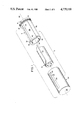
- FIG. 1 is an exploded perspective view illustrating the components of a wet film strip retaining cassette in accordance with the present invention
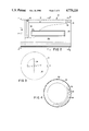
- FIG. 2 is a front elevation in partial cross section illustrating the assembled cassette shown in FIG. 1;
- FIG. 3 is an end elevation as seen on line 3--3 of FIG. 2;
- FIG. 4 is a cross section on line 4--4 of FIG. 2;
- FIGS. 5 and 6 are cross sections taken on line 5--5 of FIG. 2 but illustrating components in different relative positions;
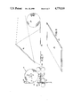
- FIG. 7 is a schematic view illustrating a film transport system using the embodiment illustrated in FIGS. 1-6;
- FIG. 8 is an isometric view illustrating a processed film assembly resulting from the embodiment illustrated in FIG. 7;
- FIG. 9 is a longitudinal cross section illustrating an integral two component film cassette employing the wet film cassette structure of the present invention.
- FIG. 10 is a fragmentary plan view illustrating a segment of the film used with the embodiment of FIG. 9.
- FIG. 11 is a cross section on line 11--11 of FIG. 10.
- a preferred embodiment of a wet film canister or cassette of the present invention is generally designated by the reference numeral 10 and is adapted to be loaded with and contain a coil of wet film strip 12 for manipulation in a camera environment to be described.
- the film component 12 is fully disclosed in the above-mentioned U.S. Pat. No. 3,907,563 and as such includes a generally resilient transparent support of mylar or similar material on which chemical materials incident to providing a positive image by diffusion transfer are coated as layers. These layers in turn are coated or impregnated with an alkaline liquid processing agent needed to carry out the diffusion transfer process when the coated layers on the transparent support are brought into face-to-face contact with an exposed negative.
- the film strip 12 is wound with the wet side facing inwardly. As a result of this winding orientation, the outside of the coil of the strip 12 is relatively dry and may be handled with ease.
- the cassette 10 includes an inner receptacle 14 having closed and open ends 16 and 18 respectively, and an outer receptacle 20 similarly having a closed end 22 and an open end 24. While the exterior configuration of the outer receptacle 20 is completely cylindrical in the illustrated embodiment of FIGS. 1-6, it is contemplated that the outside shape of the receptacle 20 will vary considerably in practice depending on structural requirements of the camera or other photographic apparatus in which the cassette 10 is to be used.
- the inner surface 26 of the outer receptacle 20, however, is principally a cylinder concentric with the central cassette axis 28 with structural formations near the inside of an axially extending rectangular slot opening 30 and near the closed end 22. Such formations will be described in more detail below.
- the inner receptacle 14 is formed with a cylindrical inner surface 32 concentric with the central cassette axis 28 and extending from the open end 18 to the base or closed end 16.
- the outer surface configuration of the inner receptacle is designed to provide a plurality of functional components which cooperate with the wet film coil 12 and with the outer receptacle 20 during use of the cassette 10 in practice.
- a pair of circular journals 36 and 38 are provided at opposite ends of a central region in the inner receptacle 14, defined axially by the length of a slot opening 34.
- the journals 36 and 38 are concentric with the axis 28 and are of a diameter effective to support the inner receptacle 14 rotatably on the inner surface 26 of the outer receptacle 20.
- a peripheral notch or cutout 40 is provided in the journal 36 at the open end 18 to allow axial insertion of the inner receptacle 14 into the outer receptacle 20 without interference by internal formations about the slot 30 to be described.
- the diameter of the journal 38 at the closed end 16 of the inner receptacle 14 is formed with a peripheral groove to receive an O-ring seal 42.
- the O-ring 42 assures a fluid-tight, hermetic seal between the inner receptacle 14 and the inner surface 26 of the outer receptacle 24 when the two receptacles are assembled, as shown in FIG. 2 of the drawings, without restricting relative rotation of the inner and outer receptacles.
- Carried on closed end 16 is a tactile discontinuity such as an indent 17 which provides an external indication of the relative position of the slot 34 within the outer receptacle 20.
- the outside peripheral configuration of the inner receptacle 14 in the central region subtended axially by the slot 34 is in substantial part defined by a cylindrical surface 44 (FIGS. 5 and 6) of the same diameter as the journals 36 and 38.
- the surface 44 extends peripherally from a sealing bar 46 at one end to a chordal flat 48 at the other end.
- the flat 48 merges with a cylindrical wall portion 50 of reduced outside diameter and which, in turn, defines one lip 52 of the slot opening 34 in the internal receptacle 14.
- Another lip 54, on the opposite side of the slot 34 from the lip 52, is defined by a volute shaped external surface portion 56 of the internal receptacle 14.
- the volute-shaped surface portion 56 lies within a cylinder containing the outside of the wall 50 and extends to a point of maximum radius near the sealing bar 46.
- the sealing bar 46 includes an outer elastomeric sealing pad 58 secured to a mounting bar 60 of generally T-shaped cross sectional configuration.
- the mounting bar includes a foot-like base formation 62 receivable in an undercut axial groove 64 in the outside of the inner receptacle 14. It is to be noted that the toe of the base formation 62 is of a radial dimension less than that of the undercut in the groove 64 so as to allow for limited radial movement or play between the sealing bar 46 and the inner receptacle 44. Also, the edge of pad 58 and mounting bar 60 facing the slot 34 is spaced radially from the volute surface 56.
- the inside of the outer receptacle 20 is shaped to complement the sealing bar and the reduced diameter portion of the inner receptacle 14 angularly opposite from the cylindrical surface portion 44.
- a sealing bar containmnent trough 66 is defined by an internal formation 68 on the outer receptacle 20.
- the formation 68 establishes a lip 70 at the approximate angular position of one edge of the slot 30, the lip being of a length at least as long as the slot 30.
- a pair of arcuate projections 72 extend from the formation 68 at opposite axial ends of the slot 30.
- relative rotation of the inner and outer receptacles 14 and 20 between the positions shown in FIGS. 5 and 6 may be effected by retaining the outer receptacle 20 against rotation and by engagement of a camera mounted key (not shown) with a key slot 74 in the closed or base end 16 of the inner receptacle 14.
- Retention of the outer receptacle 20 against rotation may be effected by a similar key slot (not shown) or by a host of other exterior surface formations in the outer receptacle 20 which may engage with complementing formations in the camera or other photographic apparatus in which the cassette 10 is used.
- the outer receptacle 20 is provided on its inner surface 26 with a radial lug 76.
- the lug 76 rides in an arcuate recess 78 formed at the open end 18 of the inner receptacle 14.
- opposite surfaces on the lug 76 abut opposite ends of the arcuate recess 78 to delimit the relative positions shown in FIGS. 5 and 6 of the drawings.
- the cassette 10 is loaded with the wet film coil 12 simply by inserting the coil into the open end of the inner receptacle 14.
- the inherent resiliency of the wet film will effect a clock spring bias of the film outwardly against the inner cylindrical surface 32 of the inner receptacle 14.
- the coil is rotatably manipulated relative to the inner receptacle so that a leading end 80 projects through the slot 34 of the inner receptacle 14. When depressed against the volute surface 56, the leading end will extend to the sealing bar 46.
- the assembly of the coil 12 and the inner receptacle 14 is inserted into the outer receptacle 20 until the O-ring seal 42 near the closed end 16 of the inner receptacle is received fully within the outer receptacle 20 (see FIG. 2).
- the receptacles 14 and 20 are then rotated to the sealed position illustrated in FIG. 6 of the drawing.
- an annular chamber is defined between the inner surface 26 of the outer receptacle 20 and the volute surface 56 of the inner receptacle 14. Also it will be noted that the volute surface 56 is spaced from the formation 68 so as to provide a clearance slightly greater than the thickness of the wet film leader 80. Hence rotation of the inner receptacle relative to the outer receptacle 20, from the sealed condition of FIG. 6 to the opened condition of FIG. 5, will cause the leader 80, biased outwardly under its inherent resilience, to project through the opening 30 in the outer receptacle.
- the length of the leader is adequate so that when the leader 80 projects from the cassette as shown in FIG. 5, it may be received in the nip between a pair of processing rollers and pulled from the cassette 10 in a manner to be described.
- the resiliency or spring back of the film coil 12 is sufficient such that the coil bears against the inner surface 22 of the inner receptacle 14 and rotates with the latter to force the leader 80 through or withdraw it within the slot opening 30 of the outer receptacle 20.
- the coil 12 bearing against the surface 22 provides means for coupling the film strip to the inner receptacle 14 to allow it to advance the leader 80 from the cassette 12 and yet also permit subsequent withdrawal of the strip from the cassette 10.
- it provides a unidirectional coupling having sufficient force to carry the strip end 80 forward or backward with rotation of the receptacle, but of low enough force to provide minimum resistance to pulling of the strip from the receptacle.
- FIG. 7 of the drawings a form of film transport system employing the cassette 10 of the present invention is schematically presented and intended for use in varied photographic apparatus. Though many camera components are omitted from the illustration in FIG. 7, it will be understood by those skilled in the art that a lens-formed light image may be folded by a mirror 82 to a focal plane in which a length of negative film strip 84 is maintained.
- the negative film strip is supplied from a light-tight cassette 86, separate from the cassette 10 in this instance, and pulled from the cassette 86 by a pair of feed rollers 88.
- the feed rollers 88 are driven by a controlled driving means (not shown) in a manner so that successive image frames may be drawn from the cassette 86 for exposure.
- the negative film strip Downstream from the feed rollers 88, the negative film strip is directed by a stationary guide 90 through the nip of a processing roller pair 92.
- a cutoff knife 94 and anvil 96 are positioned between the feed rollers 88 and the guide 90. Though shown only schematically in FIG. 7, the cut-off knife 94 is preferably of a traversing roller type in which the knife 94 rotates across the width of the negative strip 84 and cooperates with the anvil 96 to shear the negative cleanly while it is retained against longitudinal movement.
- the wet, positive film strip 12 is fed past a cut-off mechanism 98, of a type substantially identical to the cut-off mechanism represented by the knife 94 and the anvil 96, directly to the nip of the processing roller pair 92 which provide both pressure applying and advancing means for the strip 12 and the strip 84.
- Initial feeding of the wet film 12 to the nip of the processing roller pair 92 is effected by manipulation of the cassette in the manner described above with respect to FIGS. 5 and 6 of the drawings.
- the initially closed cassette 10 (FIG. 6) is operated to rotate the inner receptacle 14 from the closed position of FIG. 6 to the open condition of FIG. 5.
- Guide means may be provided to guide the end 80 along an appropriate path to the rollers 92.
- the feed roller pair 88 for the negative film strip 84 may be released so that the strip 84 and the wet strip 12 are drawn by and sandwiched together by the processing rollers 92 for a length approximating the length of an image frame previously exposed on the negative strip 84.
- the negative film strip 84 is cut by operation of the cutter 94 and 96 and the wet strip 12 is cut by the cut-off mechanism 98. These two cut-off mechanisms are operated so that the length of the negative sheet in the processed assembly of the negative strip 84 and the wet strip 12, as shown in FIG.
- the negative strip 84 is longer to define marginal extensions on opposite end of the assembly so that the rollers 92 do not contact the wetted surface of the wet strip 12 and thus are not contaminated by the fluid carried thereon. In this manner, the negative strip 84 is advanced into the nip of the processing rollers 92 slightly in advance of the leading end of the wet strip 12 and the cut length of both may be adjusted accurately in accordance with the distance between the nip of rollers 92 and the respective cutters 94 and 98.
- the length of the tongue 80 (FIGS. 5 and 6) is made long enough for its distal end to extend within the nip of rollers 92 when the inner receptacle 14 is rotated to align the openings 30 and 34.
- means are provided for at least temporarily increasing the path length from the inner slot 34 to the rollers 92 in anticipation of the removal of the strip section between the cut-off mechanism 98 and the rollers 92.
- the inner receptacle 14 is rewound or rotated backward a distance toward its sealed position prior to cutting of the wet strip 12 while the strip is held by the rollers 92.
- a switch 99 cooperates with the indent 17 to allow this positioning of the inner receptacle 14 so that the added length of the strip extending from slot 34 will equal the distance between the cutter 98 and the nip of the rollers 92. Consequently, upon cutting of the strip 12, the tongue length as measured from the slot 34 in the inner receptacle 14 will equal the original tongue length.
- the clockwise rotation of the inner receptacle 14 to move its slot 34 further from the rollers prior to cutting provides means for increasing the path length of the extended portion of the strip 12 in compensation for the length of the tongue to be removed in the cutting operation. Any of a number of ways of increasing this extended length will be suitable.
- the indent 17 is carried by the receptacle 14 to make a cassette 10 a self-contained modular unit which merely requires an appropriate position of the switch 99 to accommodate the anticipated length of removed tongue, however, it should be understood that the slot 74, or the drive blade (not shown) which engages the latter could also be employed for signaling the appropriate length of reversal of the inner receptacle. Moreover, the latter may duly be provided under control of the exposure sequencing mechanism of the camera.
- this displacement of the slot 34 along the wet strip 12 is accomplished just prior to cutting of the strip thereby maintaining both slots 30 and 34 in alignment during the drawing of the strip 12 from the cassette 10, however, the step of lengthening the strip path could occur at any point in the cycle (prior to cutting) once the wet strip is captured in the nip of the rollers 92.
- the rollers 92 provide the force for holding the strip 12 as the path is lengthened, however, any means for holding the extended strip would be suitable.
- portions of the cut-off mechanism 98 could grip and hold the strip, preferably its margins, while the path is lengthened, and then subsequently released.
- the complete cassette 20 could be slightly rotated clockwise or translated slightly away from the rollers 92 prior to the cutting step and then returned to its initial position for extension of the new tongue in a subsequent exposure and process cycle.
- a displaceable guide member (not shown) could alternatively urge the strip 12 into a deflected path to the cut-off mechanism 98.
- the system could carry a separate set of feed rollers located between the cassette 10 and the cutter 98.
- the initial length of the tongue would be equal to the length to the cutter 98, and the additional rollers would preferably be made to release the film once the tongue has reached the processing rollers 92, thereby permitting control to pass to the latter and the free withdrawal of the tongue at the end of each cycle. In this manner, the tongue remains the same length after each operation.
- the cassette 10 is inserted in the camera as shown in FIG. 7 with its slot 74 engaged by a blade (not shown) of the camera drive. Initially, the slot position is as shown dotted in FIG. 7, and in this position the cassette 10 is sealed by location of the sealing pad 58 in engagement with the slot 30 in the outer receptacle 20 as shown in FIG. 6.
- the film cassette 86 is also inserted in the camera with a leader portion extending to the rollers 88.
- the leader is driven by the rollers 88 to rollers 92 and through them until a length of unexposed negative is presented to the image area defined by the mirror 82.
- the drive of the rollers is then stopped and the cutter 94 actuated to cut off the leader section so as to leave an appropriate length of negative film 84 in the exposure plane.
- the camera apparatus operates through the following sequence. Initially, the shutter (not shown) is actuated to expose the negative 84, and the rollers 88 actuated to advance the end of the film 84 to the guide 90 and into the nip of the rollers 92. Then, the innner receptacle 14 is rotated counterclockwise to extend the tongue of the wet strip 12 to rollers 92 for engagement with the negative film 84. Rollers 92 are then actuated to advance the negative film 84 and the wet strip 12 into a superimposed relationship.
- the inner receptacle 14 carries sealing bar 46 so that the slot opening 34 is automatically sealed and unsealed in synchronism with retraction and extension of the tongue. While this arrangement is preferred, it should also be understood that the sealing function could also be provided by an external stopper and, although the simplicity of providing both functions may then be reduced, the advantage of retaining the end of the film within the cassette at all times except when in use would still be preserved.
- FIGS. 9-11 of the drawings an alternative embodiment of the invention is illustrated in which parts corresponding to parts previously identified in FIGS. 1-8 are designated by reference numerals having the same tens and digits values, but in a "100" series. Parts not previously identified, but added to the embodiment of FIGS. 9-11 are designated by reference numerals between 100 and 110.
- an integrated cassette embodiment 100 is illstrated and which is similar to the cassette structures shown in the aforementioned copending U.S. application Ser. Nos. 747,899 and 747,901, in that the containers 100 and 186 for the positive and negative film components of the two component system are interconnected by a central tray-like section 102.
- the negative film component 184 is trained from the housing 186 over the tray section 102 for successive frame exposures in the manner described above with respect to FIG. 7.
- the housing 10 Apart from the modification of the exterior conformation of the housing 10, it is substantially identical in construction to the cassette 10 described above with reference to FIGS. 1-6.
- the negative feed roll and cut-off assembly is omitted in the embodiment of FIGS. 9-10.
- the successive image frames on the film are delineated by perforated tear lines 103.
- the length of each negative frame, delimited by successive tear lines is slightly longer than the length to which the positive film strip 112 is cut by the cut-off mechanism 198.
- the initial training of the negative film strip 184 through the nip of the processing rollers may be effected by a dark sheet leader.
- the first frame of the negative sheet 184 will be presented on the tray section 102 for a subsequent exposure, but with the leading end portion of the negative film strip between the nip of the processing roller pair.
- the internal receptacle 114 of the housing 110 is rotated to move the sealing bar to the position shown in FIG. 9 and to extend a leading portion 180 of the wet film strip 112 to the nip of the processing roller pair 192.
- both the wet film strip 112 and the negative film strip 184 will be brought together in face-to-face contact for the length of the image frame to be formed.
- the internal receptacle is rotated slightly clockwise and the positive film strip is severed with the processing rollers maintained in a stationary condition and the remainder of the wet film unit 112 is then pulled through the rollers 192 with the negative film strip 184.
- the exposed and processed portion of the negative film strip 184 will tear from the section of the negative strip 184 remaining between the processing roller pair.
- the portions of the negative film strip 184 on opposite sides of the perforate tear lines 103 be provided with a very thin spacer or inert coating layer 104. In this way, very clean marginal edges will result at the leading and trailing edges of the positive film 112 on which the ultimate photograph is produced.
- the cassette 10 is supplied with a coil of wet film 12; however, it should be understood that the arrangement applies equally well to the negative film to minimize its exposure to the environment within the camera structure, and in fact, is applicable in any arrangement where intermittent dispensing of a strip and protection are desired.
Landscapes
- Physics & Mathematics (AREA)
- General Physics & Mathematics (AREA)
- Photographic Developing Apparatuses (AREA)
Abstract
Description
Claims (23)
Priority Applications (1)
| Application Number | Priority Date | Filing Date | Title |
|---|---|---|---|
| US06/922,328 US4779110A (en) | 1986-10-23 | 1986-10-23 | Wet film cassette and transport system |
Applications Claiming Priority (1)
| Application Number | Priority Date | Filing Date | Title |
|---|---|---|---|
| US06/922,328 US4779110A (en) | 1986-10-23 | 1986-10-23 | Wet film cassette and transport system |
Publications (1)
| Publication Number | Publication Date |
|---|---|
| US4779110A true US4779110A (en) | 1988-10-18 |
Family
ID=25446897
Family Applications (1)
| Application Number | Title | Priority Date | Filing Date |
|---|---|---|---|
| US06/922,328 Expired - Lifetime US4779110A (en) | 1986-10-23 | 1986-10-23 | Wet film cassette and transport system |
Country Status (1)
| Country | Link |
|---|---|
| US (1) | US4779110A (en) |
Cited By (8)
| Publication number | Priority date | Publication date | Assignee | Title |
|---|---|---|---|---|
| US5275347A (en) * | 1992-01-10 | 1994-01-04 | Management Graphics, Inc. | Autothread mechanism for strip material |
| US5453804A (en) * | 1994-08-31 | 1995-09-26 | Polaroid Corporation | Camera with film processing means |
| EP0763769A1 (en) * | 1995-09-13 | 1997-03-19 | Polaroid Corporation | A camera with film processing means |
| US5893001A (en) * | 1996-11-06 | 1999-04-06 | Eastman Kodak Company | Film cassette |
| US5974263A (en) * | 1995-10-27 | 1999-10-26 | Polaroid Corporation | Single use camera employing self-developing film and method thereof |
| US6019309A (en) * | 1998-01-28 | 2000-02-01 | Eastman Kodak Company | Cassette for photosensitive material |
| US6074107A (en) * | 1988-10-31 | 2000-06-13 | Canon Kabushiki Kaisha | Camera system |
| US6707990B1 (en) | 1995-10-27 | 2004-03-16 | Polaroid Corporation | Single use camera employing self-developing film and method thereof |
Citations (6)
| Publication number | Priority date | Publication date | Assignee | Title |
|---|---|---|---|---|
| US3043534A (en) * | 1957-08-23 | 1962-07-10 | Ralph Norris Ltd | Photographic film cassettes or containers |
| US3159357A (en) * | 1962-09-14 | 1964-12-01 | Orests B Berlings | Photographic film cassettes |
| US3249031A (en) * | 1964-02-07 | 1966-05-03 | Polaroid Corp | Photographic apparatus for treating a sheet with a liquid |
| US3424072A (en) * | 1966-08-19 | 1969-01-28 | R W Hodgson | Photographic apparatus on a camera for producing transfer prints |
| US4630912A (en) * | 1985-06-24 | 1986-12-23 | Polaroid Corporation | Wet processing web camera and method |
| US4630915A (en) * | 1985-06-24 | 1986-12-23 | Polaroid Corporation | Multipart cassette for two component film system |
-
1986
- 1986-10-23 US US06/922,328 patent/US4779110A/en not_active Expired - Lifetime
Patent Citations (6)
| Publication number | Priority date | Publication date | Assignee | Title |
|---|---|---|---|---|
| US3043534A (en) * | 1957-08-23 | 1962-07-10 | Ralph Norris Ltd | Photographic film cassettes or containers |
| US3159357A (en) * | 1962-09-14 | 1964-12-01 | Orests B Berlings | Photographic film cassettes |
| US3249031A (en) * | 1964-02-07 | 1966-05-03 | Polaroid Corp | Photographic apparatus for treating a sheet with a liquid |
| US3424072A (en) * | 1966-08-19 | 1969-01-28 | R W Hodgson | Photographic apparatus on a camera for producing transfer prints |
| US4630912A (en) * | 1985-06-24 | 1986-12-23 | Polaroid Corporation | Wet processing web camera and method |
| US4630915A (en) * | 1985-06-24 | 1986-12-23 | Polaroid Corporation | Multipart cassette for two component film system |
Cited By (8)
| Publication number | Priority date | Publication date | Assignee | Title |
|---|---|---|---|---|
| US6074107A (en) * | 1988-10-31 | 2000-06-13 | Canon Kabushiki Kaisha | Camera system |
| US5275347A (en) * | 1992-01-10 | 1994-01-04 | Management Graphics, Inc. | Autothread mechanism for strip material |
| US5453804A (en) * | 1994-08-31 | 1995-09-26 | Polaroid Corporation | Camera with film processing means |
| EP0763769A1 (en) * | 1995-09-13 | 1997-03-19 | Polaroid Corporation | A camera with film processing means |
| US5974263A (en) * | 1995-10-27 | 1999-10-26 | Polaroid Corporation | Single use camera employing self-developing film and method thereof |
| US6707990B1 (en) | 1995-10-27 | 2004-03-16 | Polaroid Corporation | Single use camera employing self-developing film and method thereof |
| US5893001A (en) * | 1996-11-06 | 1999-04-06 | Eastman Kodak Company | Film cassette |
| US6019309A (en) * | 1998-01-28 | 2000-02-01 | Eastman Kodak Company | Cassette for photosensitive material |
Similar Documents
| Publication | Publication Date | Title |
|---|---|---|
| US3451818A (en) | Composite rollfilm assembly for use in the diffusion transfer process | |
| GB2197726A (en) | Photographic camera package | |
| US2435719A (en) | Photographic apparatus for subjecting a photographic film to a processing fluid | |
| US4779110A (en) | Wet film cassette and transport system | |
| US4375324A (en) | Disposable processing kit containing film | |
| US2435717A (en) | Developing camera utilizing a film, another sheet material, and a fluid processing agent | |
| US3722383A (en) | Unique waste-free camera system of the self-developing type | |
| US4291966A (en) | Photographic film assemblage | |
| US3152529A (en) | Photographic apparatus | |
| US4523825A (en) | Film processing apparatus and system | |
| CA1180586A (en) | Combined storing, transporting, exposing and processing apparatus for camera | |
| US3807840A (en) | Film handling cassette having reel locking means | |
| EP0101732B1 (en) | Film processing kit | |
| US4630915A (en) | Multipart cassette for two component film system | |
| US4566772A (en) | Film processor for premounted transparency frames | |
| US4630912A (en) | Wet processing web camera and method | |
| US3565526A (en) | Cassette for a copying machine | |
| US4417799A (en) | Disposable manually operable film processor | |
| US4272178A (en) | Processing apparatus for self-developing type roll film | |
| US3894796A (en) | Motion picture system and apparatus | |
| US4568163A (en) | Camera back | |
| US3741095A (en) | Photographic apparatus for handling film units of the self processingtype | |
| US4693576A (en) | Camera for producing fully mounted transparencies | |
| US2909977A (en) | Photographic product | |
| US3238858A (en) | Self-developing camera |
Legal Events
| Date | Code | Title | Description |
|---|---|---|---|
| AS | Assignment |
Owner name: POLAROID CORPORATION, 549 TECHNOLOGY SQUARE, CAMBR Free format text: ASSIGNMENT OF ASSIGNORS INTEREST.;ASSIGNOR:STELLA, JOSEPH A.;REEL/FRAME:004639/0277 Effective date: 19861015 Owner name: POLAROID CORPORATION, A CORP OF DE,MASSACHUSETTS Free format text: ASSIGNMENT OF ASSIGNORS INTEREST;ASSIGNOR:STELLA, JOSEPH A.;REEL/FRAME:004639/0277 Effective date: 19861015 |
|
| STCF | Information on status: patent grant |
Free format text: PATENTED CASE |
|
| FEPP | Fee payment procedure |
Free format text: PAYOR NUMBER ASSIGNED (ORIGINAL EVENT CODE: ASPN); ENTITY STATUS OF PATENT OWNER: LARGE ENTITY |
|
| FPAY | Fee payment |
Year of fee payment: 4 |
|
| FPAY | Fee payment |
Year of fee payment: 8 |
|
| FPAY | Fee payment |
Year of fee payment: 12 |
|
| AS | Assignment |
Owner name: MORGAN GUARANTY TRUST COMPANY OF NEW YORK, NEW YOR Free format text: SECURITY AGREEMENT;ASSIGNOR:POLAROID CORPORATION;REEL/FRAME:011658/0699 Effective date: 20010321 |
|
| AS | Assignment |
Owner name: OEP IMAGINIG OPERATING CORPORATION, NEW YORK Free format text: ASSIGNMENT OF ASSIGNORS INTEREST;ASSIGNOR:POLAROID CORPORATION;REEL/FRAME:016427/0144 Effective date: 20020731 Owner name: POLAROID CORPORATION, NEW YORK Free format text: CHANGE OF NAME;ASSIGNOR:OEP IMAGING OPERATING CORPORATION;REEL/FRAME:016470/0006 Effective date: 20020801 Owner name: OEP IMAGINIG OPERATING CORPORATION,NEW YORK Free format text: ASSIGNMENT OF ASSIGNORS INTEREST;ASSIGNOR:POLAROID CORPORATION;REEL/FRAME:016427/0144 Effective date: 20020731 Owner name: POLAROID CORPORATION,NEW YORK Free format text: CHANGE OF NAME;ASSIGNOR:OEP IMAGING OPERATING CORPORATION;REEL/FRAME:016470/0006 Effective date: 20020801 |
|
| AS | Assignment |
Owner name: WILMINGTON TRUST COMPANY, AS COLLATERAL AGENT, DEL Free format text: ASSIGNMENT OF ASSIGNORS INTEREST;ASSIGNORS:POLAROLD HOLDING COMPANY;POLAROID CORPORATION;POLAROID ASIA PACIFIC LLC;AND OTHERS;REEL/FRAME:016602/0332 Effective date: 20050428 Owner name: JPMORGAN CHASE BANK,N.A,AS ADMINISTRATIVE AGENT, W Free format text: SECURITY INTEREST;ASSIGNORS:POLAROID HOLDING COMPANY;POLAROID CORPORATION;POLAROID ASIA PACIFIC LLC;AND OTHERS;REEL/FRAME:016602/0603 Effective date: 20050428 Owner name: WILMINGTON TRUST COMPANY, AS COLLATERAL AGENT,DELA Free format text: SECURITY AGREEMENT;ASSIGNORS:POLAROLD HOLDING COMPANY;POLAROID CORPORATION;POLAROID ASIA PACIFIC LLC;AND OTHERS;REEL/FRAME:016602/0332 Effective date: 20050428 Owner name: JPMORGAN CHASE BANK,N.A,AS ADMINISTRATIVE AGENT,WI Free format text: SECURITY INTEREST;ASSIGNORS:POLAROID HOLDING COMPANY;POLAROID CORPORATION;POLAROID ASIA PACIFIC LLC;AND OTHERS;REEL/FRAME:016602/0603 Effective date: 20050428 Owner name: WILMINGTON TRUST COMPANY, AS COLLATERAL AGENT, DEL Free format text: SECURITY AGREEMENT;ASSIGNORS:POLAROLD HOLDING COMPANY;POLAROID CORPORATION;POLAROID ASIA PACIFIC LLC;AND OTHERS;REEL/FRAME:016602/0332 Effective date: 20050428 |
|
| AS | Assignment |
Owner name: POLAROID CORPORATION (F/K/A OEP IMAGING OPERATING Free format text: U.S. BANKRUPTCY COURT DISTRICT OF DELAWARE ORDER AUTHORIZING RELEASE OF ALL LIENS;ASSIGNOR:JPMORGAN CHASE BANK, N.A. (F/K/A MORGAN GUARANTY TRUST COMPANY OF NEW YORK);REEL/FRAME:016621/0377 Effective date: 20020418 Owner name: POLAROID CORPORATION (F/K/A OEP IMAGING OPERATING COMPANY), MASSACHUSETTS Free format text: U.S. BANKRUPTCY COURT DISTRICT OF DELAWARE ORDER AUTHORIZING RELEASE OF ALL LIENS;ASSIGNOR:JPMORGAN CHASE BANK, N.A. (F/K/A MORGAN GUARANTY TRUST COMPANY OF NEW YORK);REEL/FRAME:016621/0377 Effective date: 20020418 |
|
| AS | Assignment |
Owner name: OEP IMAGING OPERATING CORPORATION,NEW YORK Free format text: ASSIGNMENT OF ASSIGNORS INTEREST;ASSIGNOR:POLAROID CORPORATION;REEL/FRAME:018584/0600 Effective date: 20020731 Owner name: OEP IMAGING OPERATING CORPORATION, NEW YORK Free format text: ASSIGNMENT OF ASSIGNORS INTEREST;ASSIGNOR:POLAROID CORPORATION;REEL/FRAME:018584/0600 Effective date: 20020731 |
|
| AS | Assignment |
Owner name: POLAROID CORPORATION (FMR OEP IMAGING OPERATING CO Free format text: SUPPLEMENTAL ASSIGNMENT OF PATENTS;ASSIGNOR:PRIMARY PDC, INC. (FMR POLAROID CORPORATION);REEL/FRAME:019077/0001 Effective date: 20070122 Owner name: POLAROID CORPORATION (FMR OEP IMAGING OPERATING CORP.), MASSACHUSETTS Free format text: SUPPLEMENTAL ASSIGNMENT OF PATENTS;ASSIGNOR:PRIMARY PDC, INC. (FMR POLAROID CORPORATION);REEL/FRAME:019077/0001 Effective date: 20070122 |
|
| AS | Assignment |
Owner name: POLAROID HOLDING COMPANY, MASSACHUSETTS Free format text: RELEASE OF SECURITY INTEREST IN PATENTS;ASSIGNOR:WILMINGTON TRUST COMPANY;REEL/FRAME:019699/0512 Effective date: 20070425 Owner name: POLAROID CORPORATION, MASSACHUSETTS Free format text: RELEASE OF SECURITY INTEREST IN PATENTS;ASSIGNOR:WILMINGTON TRUST COMPANY;REEL/FRAME:019699/0512 Effective date: 20070425 Owner name: POLAROID CAPITAL LLC, MASSACHUSETTS Free format text: RELEASE OF SECURITY INTEREST IN PATENTS;ASSIGNOR:WILMINGTON TRUST COMPANY;REEL/FRAME:019699/0512 Effective date: 20070425 Owner name: POLAROID ASIA PACIFIC LLC, MASSACHUSETTS Free format text: RELEASE OF SECURITY INTEREST IN PATENTS;ASSIGNOR:WILMINGTON TRUST COMPANY;REEL/FRAME:019699/0512 Effective date: 20070425 Owner name: POLAROID EYEWEAR LLC, MASSACHUSETTS Free format text: RELEASE OF SECURITY INTEREST IN PATENTS;ASSIGNOR:WILMINGTON TRUST COMPANY;REEL/FRAME:019699/0512 Effective date: 20070425 Owner name: POLOROID INTERNATIONAL HOLDING LLC, MASSACHUSETTS Free format text: RELEASE OF SECURITY INTEREST IN PATENTS;ASSIGNOR:WILMINGTON TRUST COMPANY;REEL/FRAME:019699/0512 Effective date: 20070425 Owner name: POLAROID INVESTMENT LLC, MASSACHUSETTS Free format text: RELEASE OF SECURITY INTEREST IN PATENTS;ASSIGNOR:WILMINGTON TRUST COMPANY;REEL/FRAME:019699/0512 Effective date: 20070425 Owner name: POLAROID LATIN AMERICA I CORPORATION, MASSACHUSETT Free format text: RELEASE OF SECURITY INTEREST IN PATENTS;ASSIGNOR:WILMINGTON TRUST COMPANY;REEL/FRAME:019699/0512 Effective date: 20070425 Owner name: POLAROID NEW BEDFORD REAL ESTATE LLC, MASSACHUSETT Free format text: RELEASE OF SECURITY INTEREST IN PATENTS;ASSIGNOR:WILMINGTON TRUST COMPANY;REEL/FRAME:019699/0512 Effective date: 20070425 Owner name: POLAROID NORWOOD REAL ESTATE LLC, MASSACHUSETTS Free format text: RELEASE OF SECURITY INTEREST IN PATENTS;ASSIGNOR:WILMINGTON TRUST COMPANY;REEL/FRAME:019699/0512 Effective date: 20070425 Owner name: POLAROID WALTHAM REAL ESTATE LLC, MASSACHUSETTS Free format text: RELEASE OF SECURITY INTEREST IN PATENTS;ASSIGNOR:WILMINGTON TRUST COMPANY;REEL/FRAME:019699/0512 Effective date: 20070425 Owner name: PETTERS CONSUMER BRANDS, LLC, MASSACHUSETTS Free format text: RELEASE OF SECURITY INTEREST IN PATENTS;ASSIGNOR:WILMINGTON TRUST COMPANY;REEL/FRAME:019699/0512 Effective date: 20070425 Owner name: PETTERS CONSUMER BRANDS INTERNATIONAL, LLC, MASSAC Free format text: RELEASE OF SECURITY INTEREST IN PATENTS;ASSIGNOR:WILMINGTON TRUST COMPANY;REEL/FRAME:019699/0512 Effective date: 20070425 Owner name: ZINK INCORPORATED, MASSACHUSETTS Free format text: RELEASE OF SECURITY INTEREST IN PATENTS;ASSIGNOR:WILMINGTON TRUST COMPANY;REEL/FRAME:019699/0512 Effective date: 20070425 Owner name: POLAROID HOLDING COMPANY,MASSACHUSETTS Free format text: RELEASE OF SECURITY INTEREST IN PATENTS;ASSIGNOR:WILMINGTON TRUST COMPANY;REEL/FRAME:019699/0512 Effective date: 20070425 Owner name: POLAROID CORPORATION,MASSACHUSETTS Free format text: RELEASE OF SECURITY INTEREST IN PATENTS;ASSIGNOR:WILMINGTON TRUST COMPANY;REEL/FRAME:019699/0512 Effective date: 20070425 Owner name: POLAROID CAPITAL LLC,MASSACHUSETTS Free format text: RELEASE OF SECURITY INTEREST IN PATENTS;ASSIGNOR:WILMINGTON TRUST COMPANY;REEL/FRAME:019699/0512 Effective date: 20070425 Owner name: POLAROID ASIA PACIFIC LLC,MASSACHUSETTS Free format text: RELEASE OF SECURITY INTEREST IN PATENTS;ASSIGNOR:WILMINGTON TRUST COMPANY;REEL/FRAME:019699/0512 Effective date: 20070425 Owner name: POLAROID EYEWEAR LLC,MASSACHUSETTS Free format text: RELEASE OF SECURITY INTEREST IN PATENTS;ASSIGNOR:WILMINGTON TRUST COMPANY;REEL/FRAME:019699/0512 Effective date: 20070425 Owner name: POLOROID INTERNATIONAL HOLDING LLC,MASSACHUSETTS Free format text: RELEASE OF SECURITY INTEREST IN PATENTS;ASSIGNOR:WILMINGTON TRUST COMPANY;REEL/FRAME:019699/0512 Effective date: 20070425 Owner name: POLAROID INVESTMENT LLC,MASSACHUSETTS Free format text: RELEASE OF SECURITY INTEREST IN PATENTS;ASSIGNOR:WILMINGTON TRUST COMPANY;REEL/FRAME:019699/0512 Effective date: 20070425 Owner name: POLAROID LATIN AMERICA I CORPORATION,MASSACHUSETTS Free format text: RELEASE OF SECURITY INTEREST IN PATENTS;ASSIGNOR:WILMINGTON TRUST COMPANY;REEL/FRAME:019699/0512 Effective date: 20070425 Owner name: POLAROID NEW BEDFORD REAL ESTATE LLC,MASSACHUSETTS Free format text: RELEASE OF SECURITY INTEREST IN PATENTS;ASSIGNOR:WILMINGTON TRUST COMPANY;REEL/FRAME:019699/0512 Effective date: 20070425 Owner name: POLAROID NORWOOD REAL ESTATE LLC,MASSACHUSETTS Free format text: RELEASE OF SECURITY INTEREST IN PATENTS;ASSIGNOR:WILMINGTON TRUST COMPANY;REEL/FRAME:019699/0512 Effective date: 20070425 Owner name: POLAROID WALTHAM REAL ESTATE LLC,MASSACHUSETTS Free format text: RELEASE OF SECURITY INTEREST IN PATENTS;ASSIGNOR:WILMINGTON TRUST COMPANY;REEL/FRAME:019699/0512 Effective date: 20070425 Owner name: PETTERS CONSUMER BRANDS, LLC,MASSACHUSETTS Free format text: RELEASE OF SECURITY INTEREST IN PATENTS;ASSIGNOR:WILMINGTON TRUST COMPANY;REEL/FRAME:019699/0512 Effective date: 20070425 Owner name: PETTERS CONSUMER BRANDS INTERNATIONAL, LLC,MASSACH Free format text: RELEASE OF SECURITY INTEREST IN PATENTS;ASSIGNOR:WILMINGTON TRUST COMPANY;REEL/FRAME:019699/0512 Effective date: 20070425 Owner name: ZINK INCORPORATED,MASSACHUSETTS Free format text: RELEASE OF SECURITY INTEREST IN PATENTS;ASSIGNOR:WILMINGTON TRUST COMPANY;REEL/FRAME:019699/0512 Effective date: 20070425 |
|
| AS | Assignment |
Owner name: POLAROID HOLDING COMPANY, MASSACHUSETTS Free format text: RELEASE OF SECURITY INTEREST IN PATENTS;ASSIGNOR:JPMORGAN CHASE BANK, N.A.;REEL/FRAME:020733/0001 Effective date: 20080225 Owner name: POLAROID INTERNATIONAL HOLDING LLC, MASSACHUSETTS Free format text: RELEASE OF SECURITY INTEREST IN PATENTS;ASSIGNOR:JPMORGAN CHASE BANK, N.A.;REEL/FRAME:020733/0001 Effective date: 20080225 Owner name: POLAROID INVESTMENT LLC, MASSACHUSETTS Free format text: RELEASE OF SECURITY INTEREST IN PATENTS;ASSIGNOR:JPMORGAN CHASE BANK, N.A.;REEL/FRAME:020733/0001 Effective date: 20080225 Owner name: POLAROID LATIN AMERICA I CORPORATION, MASSACHUSETT Free format text: RELEASE OF SECURITY INTEREST IN PATENTS;ASSIGNOR:JPMORGAN CHASE BANK, N.A.;REEL/FRAME:020733/0001 Effective date: 20080225 Owner name: POLAROID NEW BEDFORD REAL ESTATE LLC, MASSACHUSETT Free format text: RELEASE OF SECURITY INTEREST IN PATENTS;ASSIGNOR:JPMORGAN CHASE BANK, N.A.;REEL/FRAME:020733/0001 Effective date: 20080225 Owner name: POLAROID NORWOOD REAL ESTATE LLC, MASSACHUSETTS Free format text: RELEASE OF SECURITY INTEREST IN PATENTS;ASSIGNOR:JPMORGAN CHASE BANK, N.A.;REEL/FRAME:020733/0001 Effective date: 20080225 Owner name: POLAROID WALTHAM REAL ESTATE LLC, MASSACHUSETTS Free format text: RELEASE OF SECURITY INTEREST IN PATENTS;ASSIGNOR:JPMORGAN CHASE BANK, N.A.;REEL/FRAME:020733/0001 Effective date: 20080225 Owner name: POLAROID CONSUMER ELECTRONICS, LLC, (FORMERLY KNOW Free format text: RELEASE OF SECURITY INTEREST IN PATENTS;ASSIGNOR:JPMORGAN CHASE BANK, N.A.;REEL/FRAME:020733/0001 Effective date: 20080225 Owner name: POLAROID CONSUMER ELECTRONICS INTERNATIONAL, LLC, Free format text: RELEASE OF SECURITY INTEREST IN PATENTS;ASSIGNOR:JPMORGAN CHASE BANK, N.A.;REEL/FRAME:020733/0001 Effective date: 20080225 Owner name: ZINK INCORPORATED, MASSACHUSETTS Free format text: RELEASE OF SECURITY INTEREST IN PATENTS;ASSIGNOR:JPMORGAN CHASE BANK, N.A.;REEL/FRAME:020733/0001 Effective date: 20080225 Owner name: POLAROID CORPORATION, MASSACHUSETTS Free format text: RELEASE OF SECURITY INTEREST IN PATENTS;ASSIGNOR:JPMORGAN CHASE BANK, N.A.;REEL/FRAME:020733/0001 Effective date: 20080225 Owner name: POLAROID ASIA PACIFIC LLC, MASSACHUSETTS Free format text: RELEASE OF SECURITY INTEREST IN PATENTS;ASSIGNOR:JPMORGAN CHASE BANK, N.A.;REEL/FRAME:020733/0001 Effective date: 20080225 Owner name: POLAROID CAPITAL LLC, MASSACHUSETTS Free format text: RELEASE OF SECURITY INTEREST IN PATENTS;ASSIGNOR:JPMORGAN CHASE BANK, N.A.;REEL/FRAME:020733/0001 Effective date: 20080225 Owner name: PLLAROID EYEWEAR I LLC, MASSACHUSETTS Free format text: RELEASE OF SECURITY INTEREST IN PATENTS;ASSIGNOR:JPMORGAN CHASE BANK, N.A.;REEL/FRAME:020733/0001 Effective date: 20080225 Owner name: POLAROID HOLDING COMPANY,MASSACHUSETTS Free format text: RELEASE OF SECURITY INTEREST IN PATENTS;ASSIGNOR:JPMORGAN CHASE BANK, N.A.;REEL/FRAME:020733/0001 Effective date: 20080225 Owner name: POLAROID INTERNATIONAL HOLDING LLC,MASSACHUSETTS Free format text: RELEASE OF SECURITY INTEREST IN PATENTS;ASSIGNOR:JPMORGAN CHASE BANK, N.A.;REEL/FRAME:020733/0001 Effective date: 20080225 Owner name: POLAROID INVESTMENT LLC,MASSACHUSETTS Free format text: RELEASE OF SECURITY INTEREST IN PATENTS;ASSIGNOR:JPMORGAN CHASE BANK, N.A.;REEL/FRAME:020733/0001 Effective date: 20080225 Owner name: POLAROID LATIN AMERICA I CORPORATION,MASSACHUSETTS Free format text: RELEASE OF SECURITY INTEREST IN PATENTS;ASSIGNOR:JPMORGAN CHASE BANK, N.A.;REEL/FRAME:020733/0001 Effective date: 20080225 Owner name: POLAROID NEW BEDFORD REAL ESTATE LLC,MASSACHUSETTS Free format text: RELEASE OF SECURITY INTEREST IN PATENTS;ASSIGNOR:JPMORGAN CHASE BANK, N.A.;REEL/FRAME:020733/0001 Effective date: 20080225 Owner name: POLAROID NORWOOD REAL ESTATE LLC,MASSACHUSETTS Free format text: RELEASE OF SECURITY INTEREST IN PATENTS;ASSIGNOR:JPMORGAN CHASE BANK, N.A.;REEL/FRAME:020733/0001 Effective date: 20080225 Owner name: POLAROID WALTHAM REAL ESTATE LLC,MASSACHUSETTS Free format text: RELEASE OF SECURITY INTEREST IN PATENTS;ASSIGNOR:JPMORGAN CHASE BANK, N.A.;REEL/FRAME:020733/0001 Effective date: 20080225 Owner name: ZINK INCORPORATED,MASSACHUSETTS Free format text: RELEASE OF SECURITY INTEREST IN PATENTS;ASSIGNOR:JPMORGAN CHASE BANK, N.A.;REEL/FRAME:020733/0001 Effective date: 20080225 Owner name: POLAROID CORPORATION,MASSACHUSETTS Free format text: RELEASE OF SECURITY INTEREST IN PATENTS;ASSIGNOR:JPMORGAN CHASE BANK, N.A.;REEL/FRAME:020733/0001 Effective date: 20080225 Owner name: POLAROID ASIA PACIFIC LLC,MASSACHUSETTS Free format text: RELEASE OF SECURITY INTEREST IN PATENTS;ASSIGNOR:JPMORGAN CHASE BANK, N.A.;REEL/FRAME:020733/0001 Effective date: 20080225 Owner name: POLAROID CAPITAL LLC,MASSACHUSETTS Free format text: RELEASE OF SECURITY INTEREST IN PATENTS;ASSIGNOR:JPMORGAN CHASE BANK, N.A.;REEL/FRAME:020733/0001 Effective date: 20080225 Owner name: PLLAROID EYEWEAR I LLC,MASSACHUSETTS Free format text: RELEASE OF SECURITY INTEREST IN PATENTS;ASSIGNOR:JPMORGAN CHASE BANK, N.A.;REEL/FRAME:020733/0001 Effective date: 20080225 |
|
| AS | Assignment |
Owner name: SENSHIN CAPITAL, LLC, DELAWARE Free format text: ASSIGNMENT OF ASSIGNORS INTEREST;ASSIGNOR:POLAROID CORPORATION;REEL/FRAME:021040/0001 Effective date: 20080415 Owner name: SENSHIN CAPITAL, LLC,DELAWARE Free format text: ASSIGNMENT OF ASSIGNORS INTEREST;ASSIGNOR:POLAROID CORPORATION;REEL/FRAME:021040/0001 Effective date: 20080415 |