US4774049A - Two and three dimensional core power distribution monitor and display - Google Patents
Two and three dimensional core power distribution monitor and display Download PDFInfo
- Publication number
- US4774049A US4774049A US06/850,196 US85019686A US4774049A US 4774049 A US4774049 A US 4774049A US 85019686 A US85019686 A US 85019686A US 4774049 A US4774049 A US 4774049A
- Authority
- US
- United States
- Prior art keywords
- core
- values
- power
- defined area
- dimensional
- Prior art date
- Legal status (The legal status is an assumption and is not a legal conclusion. Google has not performed a legal analysis and makes no representation as to the accuracy of the status listed.)
- Expired - Lifetime
Links
Images


Classifications
-
- G—PHYSICS
- G21—NUCLEAR PHYSICS; NUCLEAR ENGINEERING
- G21C—NUCLEAR REACTORS
- G21C17/00—Monitoring; Testing ; Maintaining
- G21C17/06—Devices or arrangements for monitoring or testing fuel or fuel elements outside the reactor core, e.g. for burn-up, for contamination
-
- G—PHYSICS
- G21—NUCLEAR PHYSICS; NUCLEAR ENGINEERING
- G21C—NUCLEAR REACTORS
- G21C17/00—Monitoring; Testing ; Maintaining
- G21C17/10—Structural combination of fuel element, control rod, reactor core, or moderator structure with sensitive instruments, e.g. for measuring radioactivity, strain
-
- Y—GENERAL TAGGING OF NEW TECHNOLOGICAL DEVELOPMENTS; GENERAL TAGGING OF CROSS-SECTIONAL TECHNOLOGIES SPANNING OVER SEVERAL SECTIONS OF THE IPC; TECHNICAL SUBJECTS COVERED BY FORMER USPC CROSS-REFERENCE ART COLLECTIONS [XRACs] AND DIGESTS
- Y02—TECHNOLOGIES OR APPLICATIONS FOR MITIGATION OR ADAPTATION AGAINST CLIMATE CHANGE
- Y02E—REDUCTION OF GREENHOUSE GAS [GHG] EMISSIONS, RELATED TO ENERGY GENERATION, TRANSMISSION OR DISTRIBUTION
- Y02E30/00—Energy generation of nuclear origin
- Y02E30/30—Nuclear fission reactors
Definitions
- This invention relates in general to apparatus and a method for monitoring a system operation and more particularly to such apparatus and method for monitoring and visually displaying the distributions of various physical quantities occurring within the core of a nuclear power reactor.
- a fissionable atom such as U 233 , U 235 , or PU 239 absorbs a neutron in its nucleus and undergoes a nuclear disintegration. This produces on the average, two fission products of lower atomic weight and great kinetic energy, several fission neutrons, also of high energy, and fission gamma rays.
- the kinetic energy of the fission products is quickly dissipated as heat in the nuclear fuel. If, concurrent with this heat generation, there is at least one neutron remaining which induces a subsequent fission, the fission reaction becomes self-sustaining and the heat generation is continuous. The heat is removed by passing a coolant through heat exchange relationship with the fuel. The reaction may be continued as long as sufficient fissionable material exists in the fuel to override the effects of fission products and other neutron absorbers which may also be present and of neutron leakage from the active region of the core.
- nuclear reactors are presently being designed, constructed and operated in which the fissionable material or nuclear fuel is contained in fuel elements which may have various shapes, such as plates, tubes or rods. These fuel elements are usually provided on their external surfaces with a corrosion resistant, non-reactive cladding which contains no fissionable material.
- the fuel elements are grouped together at fixed distances from each other in a coolant flow channel or region as a fuel assembly, and a sufficient number of fuel assemblies are arranged in a spaced array to form the nuclear reactor core capable of the self-sustained fission reaction referred to above.
- the core is usually enclosed within a reactor vessel.
- a neutron absorbing element is included within the cooling medium (which also functions as a moderator) in controlled variable concentrations to modify the reactivity, and thus the rate of heat generation within the core, when required.
- control rods are interspersed among the fuel assemblies, longitudinally movable axially within the core, to control the core's reactivity and thus its power output.
- Control of the nuclear power distribuion within the core is a primary consideration in nuclear reactor operation.
- a mal-distribution may be detected by analysis of data from in-core and/or ex-core instrumentation.
- One conventional technique for monitoring the core power distribution involves the monitoring of the neutron flux distribution or the fission gamma ray distribution at a large number of locations within the core with the aid of fixed in-core detectors. While this approach is reliable and effective in satisfying its intended purpose, it tends to be relatively expensive to implement and so it is not universally followed.
- the alternative technique relies in the main on the use of a small number of sets of comparatively inexpensive ex-core neutron detectors arranged around the outside of the reactor vessel.
- the movable in-core system is a complex mechanical one which is subject to wear induced failures or malfunctions of its components. While it can be called upon to perform many duties related to power distribution monitoring, such increased usage is at a risk of increased system unreliability and of sharply increased maintenance requirements.
- thermocouples are installed at or just above the outlet nozzles of a fraction of the fuel assemblies in most commercial pressurized water nuclear power reactors.
- Typical reactor cores generally consist of from approximately one hundred to more than two hundred assemblies and the thermocouples are usually installed at approximately one out of four fuel assembly locations.
- the on-line plant process computer periodically samples the thermocouple voltages, converts the electrical samples into digital values in convenient engineering units, °F. or °C., and displays the results in the form of a core coolant outlet temperature map generated on a line printer.
- the plant computer also converts the core coolant outlet temperature values at the measured locations to equivalent F.sub. ⁇ H values, i.e. the relative enthalpy rises, at those locations and displays the results in map form on the line printer.
- the plant computer also provides a crude measure of quadrant power tilting by comparing F.sub. ⁇ H values at symmetric thermocouple locations.
- thermocouple maps to identify changes in the readings of certain thermocouples which would confirm the existence, and identify the possible cause, of the power distribution anomaly.
- the information available from the core-exit thermocouple system is virtually never used as a primary diagnostic means and is not used in actually formulating estimates of the current core power distribution.
- this invention provides, in general, a monitoring sensor system for evaluating, combining and displaying parameters monitored by a plurality of ex-core sensors over a defined area divided into a plurality of zones.
- the monitoring system generates both on-line, real time displays of two dimensional and three dimensional reactor core power distribution characteristics for use in reactor operation and surveillance and off-line, periodically updated detailed summaries of three dimensional reactor core power and burnup distributions for use in future reactor core fuel design activities.
- the plurality of sensors are positioned to monitor at least a portion of the zones within the defined area.
- Each of the sensors provides an output representative of the corresponding parameter monitored.
- means are provided for computing physical quantities from the outputs of the sensors and for interpolating among the physical quantities to provide display outputs representative of the interpolated value of the physical quantities in two dimensions in each of the corresponding zones. The respective interpolated values are then visually displayed according to each of the corresponding zones.
- means are provided for integrating the physical quantities derived from the outputs of the core-exit thermocouples with other physical quantities derived from ex-core neutron detectors to provide information relevant to the full three dimensional reactor core power distribution and the full three dimensional reactor core burnup distribution, and for visually displaying and permanently recording this information.
- a first aspect of the inventive system comprises a visual display system suitable for displaying two dimensional (X-Y) characteristics of nuclear power reactor core power distributions in a PWR nuclear power reactor environment.
- a reactor radial core power distribution is displayed by using color modulation over a core map display--the more brightly colored areas in the map corresponding to the hotter areas of the core.
- the active display area is divided into blocks, each representing a fuel assembly or a portion of a fuel assembly. Interpolation for assemblies not monitored directly by thermocouples is provided for a coherent display.
- visual alarm provisions are described for indicating physical quantities which are outside predetermined limits.
- a radial power monitor which uses the output signals from core-exit thermocouples to calculate two dimensional, assemblywise X-Y power distributions.
- One of the visual displays produced comprises deviations of the derived X-Y power distribution from a reference X-Y power distribution determined from a periodically determined full-core flux map obtained with an in-core movable detector system or from a defined reference X-Y power distribution obtained earlier through use of the core-exit thermocouple system.
- the deviations are calculated and presented to an operator on a high-resolution color-graphic CRT either to demonstrate that no anomalies in power distribution exist in the core or to identify any apparent anomalies that exist in the core power distribution.
- a second aspect of the inventive system comprises a computational, visual display, and permanent recording system suitable for synthesizing, displaying and recording three dimensional (X-Y-Z) characteristics of nuclear power reactor core power and burnup distributions in a PWR nuclear power reactor environment.
- the results of a three dimensional reactor core power distribution synthesis developed from ex-core neutron detector or few-string fixed in-core detector signals, by application of well known methodology, is refined and modified by a novel method that utilizes the information obtainable from core-exit thermocouples to generate an on-line, real time estimate of the actual three-dimensional reactor core power distribution that more faithfully reproduces the actual three dimensional power distribution of the reactor core than does the unrefined and unmodified three dimensional power distribution derived exclusively from the ex-core nuclear detector or few-string fixed in-core detector signals.
- the synthesized three dimensional power distribution information is then cast in a form suitable for producing one dimensional, two dimensional and psuedo-three dimensional visual displays of the reactor core power distribution characteristics based, in part, on the color modulation display methods noted above.
- specific embodiments of this second aspect of the present invention are directed toward a three dimensional core power monitor (CPM) which combines the signals from the ex-core neutron detectors or from a few strings of fixed in-core detectors with signals from the core-exit thermocouples to calculate three dimensional nodal X-Y-Z power distributions and to accumulate three dimensional nodal core burnups.
- CPM three dimensional core power monitor
- Several of the visual displays produced comprise deviations of the derived X-Y-Z power distribution from a reference X-Y-Z power distribution at successive selected elevations in the core.
- the X-Y-Z power distribution is determined from a periodical full core flux map obtained with an in-core movable detector system or from analytical three dimensional calculations of core characteristics. The deviations are calculated and presented to an operator in pseudo three dimensional form on a high resolution color-graphics CRT that is sufficiently precise to identify any apparent anomalies in the core power distribution.
- the CPM is periodically recalibrated based on in-core flux maps to assure system accuracy.
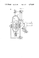
- FIG. 1 is a schematic diagram of a typical pressurized water reactor (PWR);
- FIG. 2 is a core map which is a plan view of the reactor core of a PWR;
- FIG. 3 is a plan view of the reactor core of a PWR which shows the relative position of fuel rod assemblies and an exemplary arrangement of core-exit thermocouples within the fuel assembly locations;
- FIG. 4 shows a block diagram of an embodiment of a first aspect of the inventive system
- FIG. 5 shows a block diagram of a portion of the embodiment of the first aspect of the inventive system which generates libraries of reference values
- FIG. 6 shows, in greater detail, a block diagram of the embodiment of the first aspect of the inventive system shown in FIG. 4;
- FIG. 7 shows a display, in accordance with the first aspect of the inventive system, of deviations from a reference relative enthalpy rise distribution in a nuclear core where a single control rod has been partially inserted into the core;
- FIG. 8 shows a block diagram of an embodiment of a second aspect of the inventive system
- FIG. 9 shows, in greater detail, a block diagram of the embodiment of the second aspect of the inventive system shown in FIG. 8.
- FIG. 10 shows a psuedo three dimensional display, in accordance with the second aspect of the inventive system, of deviations from a reference three dimensional power distribution in a nuclear core when a bank of control rods has been partially inserted in the core in compensation for a core power level reduction.
- FIG. 1 shows a schematic representation of the nuclear steam supply system 100 of a typical pressurized water reactor (PWR) 1 for generating electric power which can employ the method and apparatus of the present invention to more accurately monitor the radial and three dimensional power profiles within the core to avoid the operating difficulties experienced by the prior art.
- PWR 1 includes a vessel 10 which forms a pressurized container when sealed by its head assembly 11.
- the vessel 10 has coolant flow inlet means 16 and coolant flow outlet means 14 formed integral with and through its cylindrical walls.
- the vessel 10 contains a nuclear reactor core 5 of the type previously described consisting mainly of a plurality of clad nuclear fuel elements 20 (only a few of which are shown) arranged in assemblies, for example assemblies 22 and 24, which generate substantial amounts of heat, depending primarily upon the position of the full length control rods such as 14. Fission reactions within the core 5 generate heat which is absorbed by a reactor coolant, for example light water, which is passed through the core 5. The heat is conveyed from the core by coolant flow entering through inlet means 16 and exiting through outlet means 14.
- a reactor coolant for example light water
- the flow exiting through outlet means 14 is conveyed through an outlet conduit, hot leg 9, to a heat exchange steam generator system 26, wherein the heated coolant flow is conveyed through tubes which are in heat exchange relationship with water which is evaporated to produce steam.
- the steam produced by the generator is commonly utilized to drive a turbine-generator 42 to produce electric power.
- the cooled reactor coolant is conveyed from the steam generator 26 through a cold leg conduit 15 by reactor coolant pump 32 to inlet means 16. After being delivered to the reactor pressure vessel 10 through inlet means 16, the coolant is forced to circulate downwardly around the outside of a core barrel assembly 12 and upward through the interior of the core 5, through the coolant channels formed by the assemblies, whereby the reactor coolant cools the core 5 and its fuel rods 20.
- a pressurizing system (not shown) is provided to maintain the pressure of the reactor coolant with certain acceptable limits.
- a closed recycling primary loop is provided with the coolant piping coupling the vessel and the steam generator.
- the vessel illustrated in FIG. 1 only shows one steam generator for clarity, however, it is adaptable for more than one such closed fluid system or loop, though, it should be understood that the number of such loops varies from plant to plant and commonly two, three, or four are employed.
- reactor core 5 The reactivity of reactor core 5 is controlled by dissolving a neutron absorber, such as boron, in the reactor coolant, and by the insertion into the core of control rods, for example control rod 14.
- a neutron absorber such as boron
- the boron concentration of the reactor coolant is regulated by a reactor makeup system 19 which extracts coolant from the cold leg 15 upstream of the reactor coolant pump 32, adds or removes boron as appropriate, and returns the coolant with the proper boron concentration to the cold leg 15 downstream of the pump 32.
- the control rods, such as control rod 14, which are made of neutron absorbing material, are inserted into and withdrawn from the reactor core 5 by a rod control system 21.
- the rod control system 21 receives commands from the reactor control system 23.
- control rods are moved in groups, which groups are referred to as control rod banks. This rod control system 21 is well known in the art and provides one measure of the position of every control rod.
- Ex-core neutron detectors such as detectors in detector systems 35 and 36 monitor the neutron flux, and therefore the power level of reactor core 5.
- most PWRs are provided with an in-core movable detector system 27 for detecting neutrons which includes a number of thimbles 29 distributed across the core 5 through which movable detectors 31 may be inserted to generate a detailed map of the power distribution in the core. Such mapping is performed periodically, such as monthly, to determine if there are any potential or actual limiting hot spots in the core.
- Some PWRs are provided with a fixed in-core detector system (not shown) in which strings of detectors are permanently positioned in thimbles similar to thimbles 29. If the number of strings of fixed in-core detectors installed in the reactor is sufficiently large (on the order of forty or more) these installations do not require the in-core movable detector system 27. However, the costs associated with the installation and use of such many-string fixed in-core detector systems tend to be relatively large and so these systems are not universally used. If the number of strings of fixed in-core detectors installed in the reactor is sufficiently small (not exceeding eight in typical installations), the associated costs are modest, but the availability of an in-core movable detector system appears to be unavoidable.
- FIG. 2 shows core map 197 which is a plan view of the reactor core 5 comprising fuel rod assemblies 62.
- thermocouples installed at or just above the outlet nozzles of a fraction of the fuel assemblies in most commercial pressurized water nuclear power reactors. These thermocouples will be referred to hereinafter as core-exit thermocouples.
- Typical reactor cores generally consist of from approximately one hundred to more than two hundred assemblies and the thermocouples are usually located at approximately one out of four fuel rod assemblies.
- FIG. 3 shows a plan view of reactor core 5 which illustrates the relative position of the fuel rod assemblies 62, along with an exemplary arrangement of the core-exit thermocouples 64 within the fuel assembly locations 62.
- the outputs from the core-exit thermocouples 64 are sent to core-exit thermocouple system 71.
- the core-exit thermocouple system 71 periodically samples the thermocouple voltages and converts them to digital values in convenient engineering units, °F. or °C.
- Temperatures corresponding to the electrical outputs from core-exit thermocouples 64 are presently printed on a line printer by the supervisory plant computer (not shown). However, information in this form does not lend itself to easy interpretation by the plant operator and is not otherwise used.
- the first aspect of present invention provides a coherent pictorial presentation of the radial power distribution for the fuel rod assemblies 62.
- the visual display employed utilizes a color display over a core map, similar to the core map 197 shown in FIG. 2.
- the display comprises deviations of the core power from reference values provided by the core flux map which is periodically made or from reference values from a previous thermocouple-generated power distribution. If there is no deviation, within certain preset limits, then the color chosen to display that fact is green. As the assembly power decreases from that of the equivalent reference, the color changes to add more and more blue. Conversely, when the assembly power increases from that of the reference, the color changes to add more and more red so as to change from yellow to orange to red.
- the active display area is divided into blocks corresponding to the relative location of the fuel assemblies 62 within the core 5 or to subregions, such as quarters of fuel assemblies at the respective relative locations.
- hypothetical temperature signals must be derived for the other three quarters of the fuel assemblies.
- a surface spline algorithm is used to interpolate for assemblies or subregions of assemblies not directly covered by thermocouples and thereby to provide a coherent display.
- visual and/or audio alarm provisions are included to indicate when either deviations from reference values or inferred absolute values of power distribution fall outside preset limits.
- Block 71 represents a core-exit thermocouple system which receives the outputs of the thermocouples, as shown in FIG. 3.
- the signals derived from the thermocouples, representative of the relative temperatures encountered within the corresponding core locations, are fed from Core-Exit Thermocouple System 71 to a Signal Processing Unit, represented by block 72 (As described below, Signal Processing Unit 72 comprises Thermocouple F.sub. ⁇ H Calculator 91 and F.sub. ⁇ H Deviation Calculator 92). Signal Processing Unit 72 processes the signals into compatible form to interface with the Interpolator 73 (As described below, Interpolator 73 comprises F.sub. ⁇ H Deviation Interpolator/Extrapolator 93, Current Assemblywise F.sub. ⁇ H Synthesizer 106, Power Distribution Deviation Calculator 103, and Relative F.sub. ⁇ H Deviation Classifier 94).
- Display Interface 74 comprises Two-Dimensional Graphics Generator 95
- Display Device 75 comprises Graphics Monitor 100
- calibration factors for use in embodiments of the present invention are calculated on a periodic basis in Core-Exit Thermocouple Calibrator Module 80 by inputting thereto measurements from (1) In-Core Movable Detector System 27 in response to data received from movable detectors 31 or from Fixed In-Core Detector System, if provided; (2) Core-Exit Thermocouple System 71 in response to data received from core-exit thermocouples 64; (3) Reactor Control System 23 in response to data received from hot-leg temperature detector 37 and cold-leg temperature detector 38; and (4) Reactor Protection System 41 in response to data received from pressure system 51-53.
- Core-Exit Thermocouple Calibrator Module 80 computes and stores the following information for use in the manner to be explained in detail below:
- thermocouples 64 (1) a library 84 of self consistent calibration factors for the individual core-exit thermocouples 64;
- a library 86 of reference relative enthalpy rise values, F.sub. ⁇ H, for the respective functioning core-exit thermocouples 64 in the reactor vessel which reference values are obtained from a core flux map provided by In-Core Movable Detector System 27 or, if provided, by a Fixed In-Core Detector System.
- the contents of library 86 are in fact a subset of the contents of library 85.
- libraries 84 through 86 and in libraries 87 through 88, noted later, are stored for later use.
- the libraries are stored in a computer memory, in another embodiment, they are stored on computer peripheral equipment such as on magnetic disk storage.
- Libraries 84 through 86 are updated infrequently, typically once each effective full power month of plant operation.
- the apparatus and methodology of systems 23, 27, 38, 41, 51-53, 71, and 80 used to create libraries 84 through 86 are well known in the art, and, as such, are not included in this disclosure.
- Core-Exit Thermocouple System 71 generates the actual coolant core-exit temperature values used in the inventive system in real time, i.e., as the measurements are received from the core-exit thermocouples 64; the core-exit thermocouples 64 are passive and operate continuously.
- Core-Exit Thermocouple System 71 which processes the output signals from the core-exit thermocouples 64, operates frequently, and in real time, in response to (1) a preset elapsed time signal, typically on a 30 second update cycle, or (2) a preset change in control bank position or (3) a change in power level signal, typically, 10 steps of control bank movement or 3 percent in power level, respectively, and initiates operation of the remainder of the system.
- a preset elapsed time signal typically on a 30 second update cycle
- a preset change in control bank position or (3) a change in power level signal typically, 10 steps of control bank movement or 3 percent in power level, respectively
- Thermocouple F.sub. ⁇ H Calculator 91 then converts the inputs into values of the difference between the enthalpy of the coolant leaving the core and that of the coolant entering the core at the fuel assemblies at which actual thermocouples are positioned, using the library of thermocouple calibration factors 84 and methods well known in the art.
- F.sub. ⁇ H values generated in Thermocouple F.sub. ⁇ H Calculator 91, F.sub. ⁇ H j (obs), and reference F.sub. ⁇ H values from library 86, F.sub. ⁇ H j (ref), are transmitted to F.sub. ⁇ H Deviation Calculator 92.
- F.sub. ⁇ H Deviation Calculator 92 then computes the fractional deviation of the currently observed F.sub. ⁇ H values for each functioning core-exit thermocouple 64 from the corresponding reference value according to the relation:
- thermocouple
- the fractional deviation values for each functioning thermocouple 64 are passed to the F.sub. ⁇ H Deviation Interpolator/Extrapolator 93 which uses the fractional deviation values, together with stored values of the geometric coordinates of the locations of the respective core-exit thermocouples, to generate a mathematical function that characterizes the distribution of the fractional deviations of F.sub. ⁇ H over the entire reactor cross section, and subsequently provides the estimated F.sub. ⁇ H fractional deviation value at each fuel assembly location and/or at the center of each quarter of each fuel assembly in the core.
- a preferred mathematical technique used to generate the estimates is referred to in the literature as the "Surface Splines Method" and is in common use in a variety of two dimensional interpolation applications.
- the deviation values of the observed parameters, as well as the estimated deviations, are transmitted to the Current Assemblywise F.sub. ⁇ H Synthesizer 106.
- the Current Assemblywise F.sub. ⁇ H Synthesizer 106 determines the assemblywise values of power, F.sub. ⁇ H, using the Library of Reference Assemblywise F.sub. ⁇ H Values 85. These assemblywise values power, F.sub. ⁇ H, are then provided to Power Distribution Deviation Calculator 103.
- the Power Distribution Deviation Calculator 103 generates the deviation values, dF XY .sub. ⁇ H, for display using the Library of Display Reference Power Distribution 89.
- Reference Updater 105 replaces the stored values in Library of Reference Display Power Distribution 89 with the current thermocouple based power distribution produced by the Current Assemblywise F.sub. ⁇ H Synthesizer 106 or the Library of Reference Assemblywise F.sub. ⁇ H Distribution 85.
- Reference Updater 105 By periodically exercising Reference Updater 105, either upon manual initiation or automatically on periodic update, during periods of reactor maneuvering, the operator can avoid generating indications of what would otherwise appear to be significant anomalies in power distribution when in fact, the so-called anomalies are simply the result of conventional operations under the operator's control, such as control bank insertion during a load reduction.
- the deviation values, dF XY .sub. ⁇ H, produced by Power Distribution Deviation Calculator 103 are then transmitted to Relative F.sub. ⁇ H Deviation Classifier 94.
- the Relative F.sub. ⁇ H Deviation Classifier 94 classifies the deviation value at each fuel assembly or quarter of a fuel assembly location according to the sign and magnitude of the deviation value and a class identification parameter is associated with the corresponding location indices. In the preferred embodiment, a total of 11 classifications are considered.
- the spectrum of fractional deviation values covered by the set of classes is continuous, with the upper bound of one class being also the lower bound of the next higher class.
- the lowest and highest classes, class 1 and class 11, in this embodiment are each unbounded on one side so as to encompass all "extreme" deviation values.
- Two-Dimensional Graphics Display Generator 95 relates the class identification parameter value to a specified color, using, in this embodiment, a look-up table. Two-Dimensional Graphics Display Generator 95 generates a block of the appropriate color corresponding to a fuel assembly or quarter of a fuel assembly at the appropriate relative location on a graphics monitor 100.
- green was chosen to correspond to class 6 with boundaries of approximately ⁇ 0.03 in F.sub. ⁇ H fractional deviation.
- the entire core cross section on the display screen would be a uniform green color.
- FIG. 7 shows a display corresponding to the case where a control rod located at coordinates D-12 was partially inserted into the core. This insertion depresses power generation in the vicinity of the control rod and causes a broadly based, moderate increase in power generation on the opposite side of the core since in this case total power output was maintained constant despite the insertion of the single control rod.
- region 501 is light blue
- region 502 is made up of progressively smaller nominally concentric areas of progressively darker blue
- region 503 is yellow
- region 504 is light orange.
- the array of class identification parameter values generated by Relative F.sub. ⁇ H Deviation Classifier 94 is periodically and automatically scanned by Alarm Assessor 96, and an audible and/or visual alarm is generated by Control Room Alarm 97 upon detection of a class identification parameter lying outside a predetermined acceptable range.
- the alarm draws the operator's attention to the fact that an anomaly of some sort exists in the core power distribution and that displays of the current deviation values and of the current absolute values should be viewed for diagnosis and evaluation.
- the core wide estimated F.sub. ⁇ H fractional deviation distribution values generated by F.sub. ⁇ H Deviation Interpolator/Extrapolator 93 are combined with the values of F.sub. ⁇ H in Reference Assemblywise F.sub. ⁇ H Distribution Library 85 in Current Assemblywise F.sub. ⁇ H Synthesizer 106 to generate current estimates of the distribution of absolute F.sub. ⁇ H values.
- An appropriate mathematical expression describing this process is:
- indices k and 1 identify the geometric location in the core cross section at which the value of F current .sub. ⁇ H;k,1 exists.
- the array of current F.sub. ⁇ H values and the appropriate location data are passed to Absolute F.sub. ⁇ H Classifier 107.
- Absolute F.sub. ⁇ H Classifier 107 sorts the absolute F.sub. ⁇ H values into classes in the same manner as was described above with respect to Relative F.sub. ⁇ H Deviation Classifier 94.
- the array of absolute class identification numbers is then passed to the Two Dimensional Graphics Display Generator 95 and is converted into a multicolor core cross-section display in which the "hotter” assemblies are indicated by progressively brighter colors, with red indicating "very hot” assemblies which are characterized by F.sub. ⁇ H values greater than a preset limit and the "cooler” assemblies, by progressively darker shades of blue. With this display an operator can immediately assess whether the core contains any assemblies that are operating at a relative power level greater than that permitted in the plant Technical Specifications.
- the array of class identification parameter values generated by Absolute F.sub. ⁇ H Classifier 107 is periodically and automatically scanned by Alarm Assessor 96, and an audible and/or visual alarm is generated upon detection of a class identification parameter lying outside a predetermined acceptable range.
- the alarm draws the operator's attention to the fact that an anomaly of some sort exists in the core power distribution and that displays of the current deviation values and of the current absolute values should be viewed for diagnosis and evaluation.
- a second aspect of this invention may be generally understood by reference to the block diagram of FIG. 8.
- Each of the individual blocks illustrated in FIG. 8 is set out in greater detail in FIG. 9.
- the preferred embodiment of this second aspect of the present invention comprises a set of computational algorithms and computational control logic embodied in computer software which is executed on a digital computer.
- block 200 represents a conventional ex-core neutron detector system consisting of one or more sets of two or more neutron sensitive nuclear detectors, for example detector sets 35 and 36 shown in FIG. 1, wherein the detectors, sometimes referred to as the "sections," of each set are arrayed one above the other over a span roughly comparable to the height of the core.
- block 201 represents a system comprised of a few (typically, four or eight) strings of fixed in-core neutron or gamma ray sensitive nuclear detectors that are arrayed in a specified pattern, either among or within selected fuel assemblies in the core. Each string consists of several (typically, four to seven) individual sensors mounted one above the other in a common thimble or tube.
- the signals derived from the sensors in block 200 or block 201 are directed to Nuclear Detector Signal Processing Unit 202 (As described below, the Nuclear Detector Signal Processing Unit 202 comprises Axial Power Distribution Synthesizer 301, Radial Power Distribution Expander 302, and Power Distribution F.sub. ⁇ H Calculator 303).
- the Nuclear Detector Signal Processing Unit 202 processes the input ex-core or incore detector signals into compatible form to be passed to Power Distribution Modifying Unit 203 (As described below, the Power Distribution Modifying Unit 203 comprises F.sub. ⁇ H Deviation Calculator 304, F.sub. ⁇ H Deviation Interpolator/Extrapolator 93 and Power Distribution Adjuster 305).
- Core-Exit Thermocouple System 71 and Thermocouple F.sub. ⁇ H Calculator 91 are identical to, and perform the same functions as, the identically numbered components described above.
- the output signals from the Power Distribution Modifying Unit 203 which are representative of the synthesized current three dimensional power distribution in the reactor core, are passed to Display Interface 204 which processes the signals into a form compatible with Display Device 205.
- This second aspect of the present invention utilizes the Core-Exit Thermocouple Calibrator 80, described above, in the same manner as noted above, to extract a library of Thermocouple Calibration Factors 84 from the results of sets of concurrently measured core flux maps and core-exit temperature maps.
- a Nuclear Detector Calibrator (not shown) generates a Library of Axial Expansion Coefficients 87.
- the methodology and techniques used to determine the values of the expansion coefficients depend to some degree on the particular type of nuclear detector used, but all utilize information derived from flux maps as input. All relevant methodologies and techniques are well known in the art.
- a Library of Radial Power Ratios 88 is generated by application of simple editing methods to the results either of one or more flux maps obtained in the applicable reactor core or of detailed three dimensional calculations using an analytical model representative of the applicable reactor core.
- the methodology for obtaining such a library is well known to those of ordinary skill in the art.
- Ex-core Neutron Detector System 200 or Few-String Fixed In-Core Detector System 201 generates nuclear detector signal values in real time, i.e. as signals are received from sensors such as the sensors of detector systems 35 and 36 shown in FIG. 1. The sensors themselves may be externally powered or self powered and operate continuously. Ex-core Neutron Detector System 200 or Few-String Fixed In-Core Detector System 201 also operates continuously to process the raw sensor signals and to pass the conditioned output signals to the Axial Power Distribution Synthesizer 301. The methodolgy and apparatus of both detector systems 200 and 201 are well known in the art and is not included in this disclosure.
- Axial Power Distribution Synthesizer 301 combines the input signals with the coefficient values stored in Library of Axial Expansion Coefficients 87 to generate a pointwise representation of the axial nuclear power distribution in the region of the reactor core nearest to, or including, the nuclear detectors. Methodologies appropriate for use in Axial Power Distribution 301 are well known in the art.
- r est i ,j,k is the "first cut" local nuclear power level at the radial location (i,j) and the axial location (k) in the reactor core;
- q k is the value at axial location (k) of the axial power distribution generated by Axial Power Distribution Synthesizer K;
- p i ,j /p i' ,j' is the radial power ratio relating local power level at radial location (i,j) to local power level at the reference radial location (i',j') at which the axial power distribution q k is defined.
- An axial core region may be defined by a unique arrangement of inserted control rods, whence control rod position information derived from Other Plant Process Monitors 300 is supplied as input to Radial Power Distribution Expander 302, or by the nuclear characteristics of the reactor fuel which may vary axially in current reactor core designs.
- the r est i ,j,k values which describe the nominal three dimensional power distribution in the reactor core are passed to Power Distribution F.sub. ⁇ H Calculator 303.
- Power Distribution F.sub. ⁇ H Calculator 303 values are determined for the relative enthalpy rise parameter F PD .sub. ⁇ Hi,j based on the nominal or estimated three dimensional power distribution values at each fuel assembly location (i,j) by application of the relations:
- N TFA is the total number of fuel assemblies in the core.
- values of the core-exit coolant temperatures generated by Core-Exit Thermocouple System 71 are passed to Thermocouple F.sub. ⁇ H Calculator 91, where values of the thermocouple relative enthalpy rise F TC .sub. ⁇ H are calculated as described above.
- the resulting values of the thermocouple relative enthalpy rise parameter F TC .sub. ⁇ H at each active core-exit thermocouple location are also transmitted to F.sub. ⁇ H Deviation Calculator 304.
- thermocouple relative enthalpy rise parameter values of the fractional deviations of the power distribution relative enthalpy rise parameter from the corresponding thermocouple relative enthalpy rise parameter are calculated according to the relation:
- thermocouple locations where e identifies the active core-exit thermocouple locations.
- fractional deviation values ⁇ F.sub. ⁇ He are input to F.sub. ⁇ H Deviation Interpolator/Extrapolator 93 where, by the methods described above, a complete two dimensional array of values of the fractional deviation of the power distribution relative enthalpy rise parameter from either measured or hypothetical thermocouple relative enthalpy rise parameter values at all fuel assembly locations is developed.
- the interpolated/extrapolated array of fractional deviation values, ⁇ F.sub. ⁇ Hij, is then recombined with the nominal three dimensional power distribution values r est i ,j,k in Power Distribution Adjuster 305.
- the recombination takes the form of:
- the adjusted three dimensional power distribution values r adjusted i ,j,k are input to Power Distribution Normalizer 306.
- Power Distribution Normalizer 306 a value of the total core output power, Q nuclear , is computed by application of the relation:
- C 1 is a constant that takes into account the units in which the values of the adjusted power distribution are expressed, the fraction of the total core volume associated with typical mesh point i,j,k and the units in which total nuclear power Q nuclear , is desired.
- h out (T hot-leg ,P) is the enthalpy of the coolant at average hot-leg temperature T hot-leg and reactor coolant system pressure P;
- ⁇ h full-power-reference is the reactor vessel enthalpy rise corresponding to operation of the reactor at rated full power, and is established by conventional calorimetric techniques during startup and early operation of the plant.
- the final pointwise values of the synthesized three dimensional core power distribution r synthesized i ,j,k are made available by Power Distribution Normalizer 306 to Alarm Assessor 307 which performs functions very similar to Alarm Assessor 96 and transmits appropriate signals to Control Room Alarm 97.
- the final pointwise values are also transmitted to Permanent Record Device 308 which is typically a magnetic tape unit or a line printer. Further, the final pointwise values are input to Three Dimensional Burnup Accumulator 309 wherein current values of the three dimensional burnup distribution are periodically updated using the relation:
- Three Dimensional Burnup Accumulator 309 also communicates periodically with Permanent Record Device 308 to permanently record current burnup distributions.
- the synthesized three dimensional core power distribution values are also passed to Pseudo Three Dimensional Graphics Generator 310.
- Pseudo Three Dimensional Graphics Generator 310 functions in a manner similar to Two Dimensional Graphics Generator 95 to develop, at a series of successive elevations in the core, color coded representations of the fractional differences or deviations between the current synthesized power distribution values and the corresponding values in a reference three dimensional pointwise power distribution, as derived either from a reference flux map or from analytical calculations.
- the pointwise values of the reference three dimensional core power distribution are stored in Library of Reference Three Dimensional Power Distribution Values 90.
- the color coding is identical to that used in the Two Dimensional Graphics Generator 95, although a different color coding scheme could be used, if warranted.
- FIG. 10 provides an illustration of a "stacked planes" pseudo three dimensional graphics display that appears on Graphics Monitor 100 after control rods ("Five Rod D Bank") have been inserted into the core in response to a power load decrease.
- axis 601 is taken along the axial direction in the core and curve 602 represents the axial power distribution in the core.
- Planes 700, 750, 800, and 850 represent radial power distributions in the core taken at axial heights indicated by points 605, 610, 615 and 620, respectively, along axis 601.
- regions 701-704 are light orange and region 705 is yellow--indicating that, on the average, the power level in the bottom quarter of the core is somewhat higher than that recorded in the reference three dimensional core power distribution stored in Library of Reference Three Dimensional Power Distribution Values 90;
- regions 751-754 are light orange, region 755 is green and region 756 is yellow--indicating again that the current core power distribution is shifted slightly toward the bottom half of the core when compared to the reference three dimensional core power distribution (this shift is expected since control rods have been inserted at the top of the core);
- regions 801-804 are yellow and region 805 is green--indicating only a slight increase in local power in the upper middle quarter of the core due to control rod insertion (the light orange regions in the lower two quarters correspond to yellow zones in the upper middle quarter and are probably the result of radial power redistribution in response to the initiating decrease in total core power level);
Landscapes
- Physics & Mathematics (AREA)
- Engineering & Computer Science (AREA)
- Plasma & Fusion (AREA)
- General Engineering & Computer Science (AREA)
- High Energy & Nuclear Physics (AREA)
- Monitoring And Testing Of Nuclear Reactors (AREA)
- Management, Administration, Business Operations System, And Electronic Commerce (AREA)
Priority Applications (5)
| Application Number | Priority Date | Filing Date | Title |
|---|---|---|---|
| US06/850,196 US4774049A (en) | 1986-04-10 | 1986-04-10 | Two and three dimensional core power distribution monitor and display |
| KR1019870003204A KR950013236B1 (ko) | 1986-04-10 | 1987-04-04 | 상대 엔탈피의 프로파일을 표시하는 센서감시장치 및 방법 |
| JP62087255A JPS62245997A (ja) | 1986-04-10 | 1987-04-10 | エンタルピー増加プロフィルを表示するセンサ監視装置 |
| EP87303141A EP0243049B1 (de) | 1986-04-10 | 1987-04-10 | Zwei- und dreidimensionale Überwachungseinrichtung für die Spaltzonenleistungsverteilung und zugehörige Anzeige |
| ES198787303141T ES2026907T3 (es) | 1986-04-10 | 1987-04-10 | Vigilancia y presentacion visual bi y tridimensional de la distribucion de potencia en el nucleo de un reactor nuclear. |
Applications Claiming Priority (1)
| Application Number | Priority Date | Filing Date | Title |
|---|---|---|---|
| US06/850,196 US4774049A (en) | 1986-04-10 | 1986-04-10 | Two and three dimensional core power distribution monitor and display |
Publications (1)
| Publication Number | Publication Date |
|---|---|
| US4774049A true US4774049A (en) | 1988-09-27 |
Family
ID=25307523
Family Applications (1)
| Application Number | Title | Priority Date | Filing Date |
|---|---|---|---|
| US06/850,196 Expired - Lifetime US4774049A (en) | 1986-04-10 | 1986-04-10 | Two and three dimensional core power distribution monitor and display |
Country Status (5)
| Country | Link |
|---|---|
| US (1) | US4774049A (de) |
| EP (1) | EP0243049B1 (de) |
| JP (1) | JPS62245997A (de) |
| KR (1) | KR950013236B1 (de) |
| ES (1) | ES2026907T3 (de) |
Cited By (31)
| Publication number | Priority date | Publication date | Assignee | Title |
|---|---|---|---|---|
| US4839134A (en) * | 1987-12-31 | 1989-06-13 | Westinghouse Electric Corp. | Continuous, online nuclear power distribution synthesis system and method |
| US4927594A (en) * | 1988-08-10 | 1990-05-22 | Westinghouse Electric Corp. | Thermocouple based control rod position indication system |
| US4975239A (en) * | 1989-01-23 | 1990-12-04 | General Electric Company | BWR core flow measurement enhancements |
| US5091139A (en) * | 1989-06-26 | 1992-02-25 | General Electric Company | Automated thermal limit monitor |
| US5297174A (en) * | 1993-05-26 | 1994-03-22 | Westinghouse Electric Corp. | Safety system grade apparatus and method for detecting a dropped control rod and malfunctioning exit thermocouples in a pressurized water reactor |
| US5490184A (en) * | 1994-07-21 | 1996-02-06 | Westinghouse Electric Corporation | Method and a system for accurately calculating PWR power from excore detector currents corrected for changes in 3-D power distribution and coolant density |
| US5613087A (en) * | 1995-02-23 | 1997-03-18 | International Business Machines Corporation | Cache testing using a modified snoop cycle command |
| US5682410A (en) * | 1995-10-17 | 1997-10-28 | General Electric Company | Method for determining core flow rate and water temperature/density in boiling water reactor |
| US5761086A (en) * | 1996-02-13 | 1998-06-02 | Westinghouse Electric Corporation | Apparatus and method for monitoring pressure-temperature margins |
| WO1999022378A1 (en) * | 1997-10-16 | 1999-05-06 | Westinghouse Electric Company Llc | Nuclear reaction protection system |
| US6211880B1 (en) | 1998-04-13 | 2001-04-03 | Albert Joseph Impink, Jr. | Display apparatus |
| EP1197970A1 (de) * | 2000-10-11 | 2002-04-17 | Westinghouse Electric Company LLC | Verfahren zur Eichung von Ausgangs-Thermoelemente in einem Kernreaktor |
| US6477218B1 (en) * | 1998-07-02 | 2002-11-05 | Hitachi, Ltd. | Control system of nuclear power plant, and control method thereof |
| US6477219B2 (en) * | 1998-03-17 | 2002-11-05 | Kabushiki Kaisha Toshiba | Nuclear reactor power distribution monitoring system and method including nuclear reactor instrumentation system |
| US20030128793A1 (en) * | 2001-09-27 | 2003-07-10 | Kabushiki Kaisha Toshiba | Incore monitoring method and incore monitoring equipment |
| US20040096101A1 (en) * | 2001-08-29 | 2004-05-20 | Masaaki Mori | Calculation method of nuclear reactor core |
| US20040195517A1 (en) * | 2002-11-19 | 2004-10-07 | The Regents Of The University Of California | Real time method and computer system for identifying radioactive materials from HPGe gamma-ray spectroscopy |
| US20060146973A1 (en) * | 2004-12-30 | 2006-07-06 | Harold Yeager | Method and system for assessing failures of fuel rods |
| US20070018110A1 (en) * | 2004-07-29 | 2007-01-25 | Mcgregor Douglas S | Micro neutron detectors |
| FR2914103A1 (fr) * | 2007-03-19 | 2008-09-26 | Areva Np Sas | Procede de determination de la distribution de puissance volumique du coeur d'un reacteur nucleaire |
| FR2917228A1 (fr) * | 2007-06-08 | 2008-12-12 | Areva Np Sas | Procede de determination d'une composante d'incertitude relative a la distribution de puissance dans le coeur d'un reacteur nucleaire |
| US20090080490A1 (en) * | 2007-09-21 | 2009-03-26 | Siemens Energy & Automation, Inc. | Systems, Devices, and/or Methods for Managing a Thermocouple Module |
| US20100158185A1 (en) * | 2005-08-31 | 2010-06-24 | Westinghouse Electric Sweden Ab | Method and apparatus of estimating dryout properties in a nuclear light water reactor |
| US20100260300A1 (en) * | 2007-12-07 | 2010-10-14 | Areva Np | Method of Determining the Value of a Parameter Representative of the Operability of a Nuclear Reactor, Determining System, Computer Program and Corresponding Medium |
| RU2438198C1 (ru) * | 2010-09-22 | 2011-12-27 | Федеральное государственное бюджетное учреждение "Национальный исследовательский центр "Курчатовский институт" | Способ защиты активной зоны реактора ввэр по локальным параметрам с использованием показаний внутриреакторных нейтронных детекторов |
| US20130243146A1 (en) * | 2012-03-13 | 2013-09-19 | Mitsubishi Electric Corporation | Ex-core nuclear instrumentation system |
| CN109918738A (zh) * | 2019-02-12 | 2019-06-21 | 中广核工程有限公司 | 核电厂反应堆功率状态三维可视化方法、评估方法及系统 |
| CN112509716A (zh) * | 2020-11-24 | 2021-03-16 | 华南理工大学 | 基于信息融合理论的反应堆三维功率概率分布监测方法 |
| WO2021090240A1 (en) * | 2019-11-08 | 2021-05-14 | Framatome Inc. | Self-powered excore detector arrangement for measuring flux of a nuclear reactor core |
| US11662719B2 (en) * | 2017-09-29 | 2023-05-30 | Rockwell Automation Technologies, Inc. | Classification modeling for monitoring, diagnostics optimization and control |
| WO2025237439A1 (zh) * | 2024-06-27 | 2025-11-20 | 深圳中广核工程设计有限公司 | 核电厂轴向功率偏差监控方法及系统、终端设备 |
Families Citing this family (5)
| Publication number | Priority date | Publication date | Assignee | Title |
|---|---|---|---|---|
| US5229066A (en) * | 1991-08-05 | 1993-07-20 | Westinghouse Electric Corp. | Control rod position indication system |
| US6404437B1 (en) * | 1999-09-10 | 2002-06-11 | General Electric Company | Nuclear reactor core performance data visualization system |
| AUPQ917000A0 (en) * | 2000-08-03 | 2000-08-24 | Valpall Pty Ltd | Method for producing an improved packaged cooked meat product |
| US20110268239A1 (en) * | 2010-04-30 | 2011-11-03 | David Jerome Krieg | Method of calibrating excore detectors in a nuclear reactor |
| CN116487084B (zh) * | 2023-04-21 | 2026-03-13 | 中广核研究院有限公司 | 核电厂运行保护方法、装置、计算机设备和存储介质 |
Citations (9)
| Publication number | Priority date | Publication date | Assignee | Title |
|---|---|---|---|---|
| US3810138A (en) * | 1972-01-10 | 1974-05-07 | Westinghouse Electric Corp | Interpolative sensor output visual map display system |
| FR2307341A1 (fr) * | 1975-04-10 | 1976-11-05 | Kraftwerk Union Ag | Reacteur nucleaire |
| US4400343A (en) * | 1978-10-18 | 1983-08-23 | Hitachi, Ltd. | System and method for controlling operation of boiling water reactor |
| US4427620A (en) * | 1981-02-04 | 1984-01-24 | Westinghouse Electric Corp. | Nuclear reactor power supply |
| EP0122172A1 (de) * | 1983-03-11 | 1984-10-17 | Framatome | Anordnung zur schnellen und genauen Bestimmung der Leistung eines Druckwasser-Kernreaktors |
| US4552718A (en) * | 1982-07-01 | 1985-11-12 | Westinghouse Electric Corp. | Method and apparatus for on-line monitoring of the operation of a complex non-linear process control system |
| US4608223A (en) * | 1982-03-01 | 1986-08-26 | The Babcock & Wilcox Company | Abnormal transient display system for nuclear reactor operation |
| US4627954A (en) * | 1983-05-19 | 1986-12-09 | Framatome & Cie. | Process for detecting faults in the power distribution of a pressurized water nuclear reactor core and device for making use of this process |
| US4650633A (en) * | 1984-07-02 | 1987-03-17 | General Electric Company | Method and apparatus for protection of pump systems |
Family Cites Families (2)
| Publication number | Priority date | Publication date | Assignee | Title |
|---|---|---|---|---|
| GB1145981A (en) * | 1964-12-17 | 1969-03-19 | United Power Company Ltd | Improvements in or relating to a method and apparatus for the visual presentation ofinformation relating to a parameter value at each of a plurality of test points |
| JPS5698682A (en) * | 1980-01-11 | 1981-08-08 | Hitachi Ltd | Method and device for monitoring fast reactor core |
-
1986
- 1986-04-10 US US06/850,196 patent/US4774049A/en not_active Expired - Lifetime
-
1987
- 1987-04-04 KR KR1019870003204A patent/KR950013236B1/ko not_active Expired - Lifetime
- 1987-04-10 JP JP62087255A patent/JPS62245997A/ja not_active Withdrawn
- 1987-04-10 EP EP87303141A patent/EP0243049B1/de not_active Expired - Lifetime
- 1987-04-10 ES ES198787303141T patent/ES2026907T3/es not_active Expired - Lifetime
Patent Citations (10)
| Publication number | Priority date | Publication date | Assignee | Title |
|---|---|---|---|---|
| US3810138A (en) * | 1972-01-10 | 1974-05-07 | Westinghouse Electric Corp | Interpolative sensor output visual map display system |
| FR2307341A1 (fr) * | 1975-04-10 | 1976-11-05 | Kraftwerk Union Ag | Reacteur nucleaire |
| US4400343A (en) * | 1978-10-18 | 1983-08-23 | Hitachi, Ltd. | System and method for controlling operation of boiling water reactor |
| US4427620A (en) * | 1981-02-04 | 1984-01-24 | Westinghouse Electric Corp. | Nuclear reactor power supply |
| US4608223A (en) * | 1982-03-01 | 1986-08-26 | The Babcock & Wilcox Company | Abnormal transient display system for nuclear reactor operation |
| US4552718A (en) * | 1982-07-01 | 1985-11-12 | Westinghouse Electric Corp. | Method and apparatus for on-line monitoring of the operation of a complex non-linear process control system |
| EP0122172A1 (de) * | 1983-03-11 | 1984-10-17 | Framatome | Anordnung zur schnellen und genauen Bestimmung der Leistung eines Druckwasser-Kernreaktors |
| US4654186A (en) * | 1983-03-11 | 1987-03-31 | Framatome & Cie. | Device for determination of the power of a pressurized water nuclear reactor |
| US4627954A (en) * | 1983-05-19 | 1986-12-09 | Framatome & Cie. | Process for detecting faults in the power distribution of a pressurized water nuclear reactor core and device for making use of this process |
| US4650633A (en) * | 1984-07-02 | 1987-03-17 | General Electric Company | Method and apparatus for protection of pump systems |
Non-Patent Citations (2)
| Title |
|---|
| Robert L. Harder, Interpolation Using Surface Splines, Feb. 1972, pp. 189 191, Journal of Aircraft. * |
| Robert L. Harder, Interpolation Using Surface Splines, Feb. 1972, pp. 189-191, Journal of Aircraft. |
Cited By (51)
| Publication number | Priority date | Publication date | Assignee | Title |
|---|---|---|---|---|
| US4839134A (en) * | 1987-12-31 | 1989-06-13 | Westinghouse Electric Corp. | Continuous, online nuclear power distribution synthesis system and method |
| US4927594A (en) * | 1988-08-10 | 1990-05-22 | Westinghouse Electric Corp. | Thermocouple based control rod position indication system |
| US4975239A (en) * | 1989-01-23 | 1990-12-04 | General Electric Company | BWR core flow measurement enhancements |
| US5091139A (en) * | 1989-06-26 | 1992-02-25 | General Electric Company | Automated thermal limit monitor |
| US5297174A (en) * | 1993-05-26 | 1994-03-22 | Westinghouse Electric Corp. | Safety system grade apparatus and method for detecting a dropped control rod and malfunctioning exit thermocouples in a pressurized water reactor |
| KR100333206B1 (ko) * | 1993-05-26 | 2002-10-18 | 웨스팅하우스 일렉트릭 코포레이션 | 가압수형원자로및그의보호방법 |
| US5490184A (en) * | 1994-07-21 | 1996-02-06 | Westinghouse Electric Corporation | Method and a system for accurately calculating PWR power from excore detector currents corrected for changes in 3-D power distribution and coolant density |
| US5613087A (en) * | 1995-02-23 | 1997-03-18 | International Business Machines Corporation | Cache testing using a modified snoop cycle command |
| US6061412A (en) * | 1995-10-05 | 2000-05-09 | Westinghouse Electric Company Llc | Nuclear reaction protection system |
| US5682410A (en) * | 1995-10-17 | 1997-10-28 | General Electric Company | Method for determining core flow rate and water temperature/density in boiling water reactor |
| US5761086A (en) * | 1996-02-13 | 1998-06-02 | Westinghouse Electric Corporation | Apparatus and method for monitoring pressure-temperature margins |
| WO1999022378A1 (en) * | 1997-10-16 | 1999-05-06 | Westinghouse Electric Company Llc | Nuclear reaction protection system |
| US6477219B2 (en) * | 1998-03-17 | 2002-11-05 | Kabushiki Kaisha Toshiba | Nuclear reactor power distribution monitoring system and method including nuclear reactor instrumentation system |
| US6211880B1 (en) | 1998-04-13 | 2001-04-03 | Albert Joseph Impink, Jr. | Display apparatus |
| US6553090B2 (en) * | 1998-07-02 | 2003-04-22 | Hitachi, Ltd. | Control system of nuclear power plant, and control method thereof |
| US6477218B1 (en) * | 1998-07-02 | 2002-11-05 | Hitachi, Ltd. | Control system of nuclear power plant, and control method thereof |
| EP1197970A1 (de) * | 2000-10-11 | 2002-04-17 | Westinghouse Electric Company LLC | Verfahren zur Eichung von Ausgangs-Thermoelemente in einem Kernreaktor |
| US6493412B1 (en) * | 2000-10-11 | 2002-12-10 | Westinghouse Electric Company Llc | Method of calibrating exit thermocouples in a nuclear reactor |
| US20040096101A1 (en) * | 2001-08-29 | 2004-05-20 | Masaaki Mori | Calculation method of nuclear reactor core |
| US20030128793A1 (en) * | 2001-09-27 | 2003-07-10 | Kabushiki Kaisha Toshiba | Incore monitoring method and incore monitoring equipment |
| US6744840B2 (en) * | 2001-09-27 | 2004-06-01 | Kabushiki Kaisha Toshiba | Incore monitoring method and incore monitoring equipment |
| US20040195517A1 (en) * | 2002-11-19 | 2004-10-07 | The Regents Of The University Of California | Real time method and computer system for identifying radioactive materials from HPGe gamma-ray spectroscopy |
| US7285784B2 (en) * | 2002-11-19 | 2007-10-23 | The Regents Of The University Of California | Real time method and computer system for identifying radioactive materials from HPGe gamma-ray spectroscopy |
| US20070018110A1 (en) * | 2004-07-29 | 2007-01-25 | Mcgregor Douglas S | Micro neutron detectors |
| US8811563B2 (en) * | 2004-12-30 | 2014-08-19 | General Electric Company | Method and system for assessing failures of fuel rods |
| US20060146973A1 (en) * | 2004-12-30 | 2006-07-06 | Harold Yeager | Method and system for assessing failures of fuel rods |
| US20100158185A1 (en) * | 2005-08-31 | 2010-06-24 | Westinghouse Electric Sweden Ab | Method and apparatus of estimating dryout properties in a nuclear light water reactor |
| US7760842B2 (en) * | 2005-08-31 | 2010-07-20 | Westinghouse Electric Sweden Ab | Method and apparatus of estimating dryout properties in a nuclear light water reactor |
| RU2448378C2 (ru) * | 2007-03-19 | 2012-04-20 | Арева Нп | Способ определения трехмерного распределения мощности в активной зоне ядерного реактора |
| US20100119026A1 (en) * | 2007-03-19 | 2010-05-13 | Antoine Gautier | Method for Determining the Three-Dimensional Power Distribution of the Core of a Nuclear Reactor |
| JP2010522319A (ja) * | 2007-03-19 | 2010-07-01 | アレバ エヌペ | 原子炉炉心の三次元出力分布を決定する方法 |
| WO2008132365A3 (fr) * | 2007-03-19 | 2008-12-31 | Areva Np | Procédé de détermination de la distribution de puissance volumique du coeur d'un réacteur nucléaire |
| FR2914103A1 (fr) * | 2007-03-19 | 2008-09-26 | Areva Np Sas | Procede de determination de la distribution de puissance volumique du coeur d'un reacteur nucleaire |
| CN101669176B (zh) * | 2007-03-19 | 2014-02-19 | 阿海珐核能公司 | 确定核反应堆堆芯三维功率分布的方法 |
| WO2009001004A3 (fr) * | 2007-06-08 | 2009-02-19 | Areva Np | Procede de determination d'une composante d'incertitude relative a la distribution de puissance dans le coeur d'un reacteur nucleaire |
| FR2917228A1 (fr) * | 2007-06-08 | 2008-12-12 | Areva Np Sas | Procede de determination d'une composante d'incertitude relative a la distribution de puissance dans le coeur d'un reacteur nucleaire |
| US8702306B2 (en) * | 2007-09-21 | 2014-04-22 | Siemens Industry, Inc. | Systems, devices, and/or methods for managing a thermocouple module |
| US20090080490A1 (en) * | 2007-09-21 | 2009-03-26 | Siemens Energy & Automation, Inc. | Systems, Devices, and/or Methods for Managing a Thermocouple Module |
| US9995640B2 (en) | 2007-09-21 | 2018-06-12 | Siemens Industry, Inc. | Systems, devices, and/or methods for managing a thermocouple module |
| US20100260300A1 (en) * | 2007-12-07 | 2010-10-14 | Areva Np | Method of Determining the Value of a Parameter Representative of the Operability of a Nuclear Reactor, Determining System, Computer Program and Corresponding Medium |
| US9997263B2 (en) * | 2007-12-07 | 2018-06-12 | Areva Np | Method of determining the value of a parameter representative of the operability of a nuclear reactor, determining system, computer and corresponding medium |
| RU2438198C1 (ru) * | 2010-09-22 | 2011-12-27 | Федеральное государственное бюджетное учреждение "Национальный исследовательский центр "Курчатовский институт" | Способ защиты активной зоны реактора ввэр по локальным параметрам с использованием показаний внутриреакторных нейтронных детекторов |
| US20130243146A1 (en) * | 2012-03-13 | 2013-09-19 | Mitsubishi Electric Corporation | Ex-core nuclear instrumentation system |
| US9368239B2 (en) * | 2012-03-13 | 2016-06-14 | Mitsubishi Electric Corporation | Ex-core nuclear instrumentation system |
| US11662719B2 (en) * | 2017-09-29 | 2023-05-30 | Rockwell Automation Technologies, Inc. | Classification modeling for monitoring, diagnostics optimization and control |
| CN109918738A (zh) * | 2019-02-12 | 2019-06-21 | 中广核工程有限公司 | 核电厂反应堆功率状态三维可视化方法、评估方法及系统 |
| CN109918738B (zh) * | 2019-02-12 | 2022-12-30 | 中广核工程有限公司 | 核电厂反应堆功率状态三维可视化方法、评估方法及系统 |
| WO2021090240A1 (en) * | 2019-11-08 | 2021-05-14 | Framatome Inc. | Self-powered excore detector arrangement for measuring flux of a nuclear reactor core |
| CN112509716A (zh) * | 2020-11-24 | 2021-03-16 | 华南理工大学 | 基于信息融合理论的反应堆三维功率概率分布监测方法 |
| CN112509716B (zh) * | 2020-11-24 | 2023-11-10 | 华南理工大学 | 基于信息融合理论的反应堆三维功率概率分布监测方法 |
| WO2025237439A1 (zh) * | 2024-06-27 | 2025-11-20 | 深圳中广核工程设计有限公司 | 核电厂轴向功率偏差监控方法及系统、终端设备 |
Also Published As
| Publication number | Publication date |
|---|---|
| KR870010561A (ko) | 1987-11-30 |
| EP0243049A3 (en) | 1988-06-29 |
| ES2026907T3 (es) | 1992-05-16 |
| EP0243049A2 (de) | 1987-10-28 |
| KR950013236B1 (ko) | 1995-10-26 |
| JPS62245997A (ja) | 1987-10-27 |
| EP0243049B1 (de) | 1991-10-16 |
Similar Documents
| Publication | Publication Date | Title |
|---|---|---|
| US4774049A (en) | Two and three dimensional core power distribution monitor and display | |
| US4774050A (en) | Axial power distribution monitor and display using outputs from ex-core detectors and thermocouples | |
| EP0396321A2 (de) | Ergänzungsverfahren für ein Kernreaktorcoremodell | |
| US20100260300A1 (en) | Method of Determining the Value of a Parameter Representative of the Operability of a Nuclear Reactor, Determining System, Computer Program and Corresponding Medium | |
| US6493412B1 (en) | Method of calibrating exit thermocouples in a nuclear reactor | |
| US4927594A (en) | Thermocouple based control rod position indication system | |
| Shieh et al. | Application of noise analysis technique for monitoring the moderator temperature coefficient of reactivity in pressurized water reactors | |
| USH289H (en) | Integrated iconic display | |
| Lucoff | Passive safety testing at the fast flux test facility | |
| RU2083005C1 (ru) | Способ контроля теплового режима первого контура аэс с реактором типа ввэр | |
| Coplen et al. | Loss-of-fluid test integral test facility and program | |
| Quapp et al. | Irradiation effects test Series Scoping Test 1: test results report.[PWR] | |
| Dean et al. | System modeling and simulation at EBR-II | |
| Chowdhury | Boiling instabilities in helical coil steam generator | |
| Olson | Semiscale blowdown and Emergency Core Cooling (ECC) project test report: Test 845 (ECC Injection) | |
| Mummery et al. | The PFR station control system | |
| Russcher et al. | LOCA simulation in the NRU reactor: materials test-1 | |
| Kott et al. | Application of integrated detection systems for in-core instrumentation of nuclear power plants | |
| Majumdar et al. | Survey and evaluation of FFTF instrumentation for systems code validation | |
| In et al. | Functional design standard of on-line digital core protection and monitoring systems for SMART | |
| Branyan et al. | NUCLEAR TEST PROGRAM FOR THE ENRICO FERMI FAST BREEDER REACTOR. | |
| Atraz | EVESR-NUCLEAR SUPERHEAT FUEL DEVELOPMENT PROJECT. DARE CODE FOR THE THERMAL HYDRAULIC FUEL PERFORMANCE EVALUATION | |
| Hodde | FUEL CYCLE PROGRAM. A BOILING WATER REACTOR RESEARCH AND DEVELOPMENT PROGRAM. Quarterly Report No. 5, July 1961-September 1961 | |
| Anderson et al. | Summary of inadequate core cooling instrumentation for US nuclear power plants | |
| Rodriguez | Recent evolution of HTGR instrumentation in the USA |
Legal Events
| Date | Code | Title | Description |
|---|---|---|---|
| AS | Assignment |
Owner name: WESTINGHOUSE ELECTRIC CORPORATION, WESTINGHOUSE BU Free format text: ASSIGNMENT OF ASSIGNORS INTEREST.;ASSIGNORS:IMPINK, ALBERT J. JR.;GROBMYER, LOUIS R.;REEL/FRAME:004539/0740 Effective date: 19860407 |
|
| STCF | Information on status: patent grant |
Free format text: PATENTED CASE |
|
| FPAY | Fee payment |
Year of fee payment: 4 |
|
| FPAY | Fee payment |
Year of fee payment: 8 |
|
| AS | Assignment |
Owner name: WESTINGHOUSE ELECTRIC CO. LLC, PENNSYLVANIA Free format text: ASSIGNMENT OF ASSIGNORS INTEREST;ASSIGNOR:CBS CORPORATION (FORMERLY KNOWN AS WESTINGHOUSE ELECTRIC CORPORATION;REEL/FRAME:010070/0819 Effective date: 19990322 |
|
| FPAY | Fee payment |
Year of fee payment: 12 |