US4768550A - Manifold fitting for a compressed air tank - Google Patents
Manifold fitting for a compressed air tank Download PDFInfo
- Publication number
- US4768550A US4768550A US07/081,753 US8175387A US4768550A US 4768550 A US4768550 A US 4768550A US 8175387 A US8175387 A US 8175387A US 4768550 A US4768550 A US 4768550A
- Authority
- US
- United States
- Prior art keywords
- opening
- face
- end portion
- passage
- closure
- Prior art date
- Legal status (The legal status is an assumption and is not a legal conclusion. Google has not performed a legal analysis and makes no representation as to the accuracy of the status listed.)
- Expired - Fee Related
Links
Images

Classifications
-
- F—MECHANICAL ENGINEERING; LIGHTING; HEATING; WEAPONS; BLASTING
- F16—ENGINEERING ELEMENTS AND UNITS; GENERAL MEASURES FOR PRODUCING AND MAINTAINING EFFECTIVE FUNCTIONING OF MACHINES OR INSTALLATIONS; THERMAL INSULATION IN GENERAL
- F16K—VALVES; TAPS; COCKS; ACTUATING-FLOATS; DEVICES FOR VENTING OR AERATING
- F16K1/00—Lift valves or globe valves, i.e. cut-off apparatus with closure members having at least a component of their opening and closing motion perpendicular to the closing faces
- F16K1/30—Lift valves or globe valves, i.e. cut-off apparatus with closure members having at least a component of their opening and closing motion perpendicular to the closing faces specially adapted for pressure containers
- F16K1/304—Shut-off valves with additional means
- F16K1/305—Shut-off valves with additional means with valve member and actuator on the same side of the seat
-
- F—MECHANICAL ENGINEERING; LIGHTING; HEATING; WEAPONS; BLASTING
- F16—ENGINEERING ELEMENTS AND UNITS; GENERAL MEASURES FOR PRODUCING AND MAINTAINING EFFECTIVE FUNCTIONING OF MACHINES OR INSTALLATIONS; THERMAL INSULATION IN GENERAL
- F16K—VALVES; TAPS; COCKS; ACTUATING-FLOATS; DEVICES FOR VENTING OR AERATING
- F16K1/00—Lift valves or globe valves, i.e. cut-off apparatus with closure members having at least a component of their opening and closing motion perpendicular to the closing faces
- F16K1/30—Lift valves or globe valves, i.e. cut-off apparatus with closure members having at least a component of their opening and closing motion perpendicular to the closing faces specially adapted for pressure containers
- F16K1/307—Additional means used in combination with the main valve
-
- F—MECHANICAL ENGINEERING; LIGHTING; HEATING; WEAPONS; BLASTING
- F17—STORING OR DISTRIBUTING GASES OR LIQUIDS
- F17C—VESSELS FOR CONTAINING OR STORING COMPRESSED, LIQUEFIED OR SOLIDIFIED GASES; FIXED-CAPACITY GAS-HOLDERS; FILLING VESSELS WITH, OR DISCHARGING FROM VESSELS, COMPRESSED, LIQUEFIED, OR SOLIDIFIED GASES
- F17C13/00—Details of vessels or of the filling or discharging of vessels
- F17C13/04—Arrangement or mounting of valves
-
- F—MECHANICAL ENGINEERING; LIGHTING; HEATING; WEAPONS; BLASTING
- F17—STORING OR DISTRIBUTING GASES OR LIQUIDS
- F17C—VESSELS FOR CONTAINING OR STORING COMPRESSED, LIQUEFIED OR SOLIDIFIED GASES; FIXED-CAPACITY GAS-HOLDERS; FILLING VESSELS WITH, OR DISCHARGING FROM VESSELS, COMPRESSED, LIQUEFIED, OR SOLIDIFIED GASES
- F17C2205/00—Vessel construction, in particular mounting arrangements, attachments or identifications means
- F17C2205/03—Fluid connections, filters, valves, closure means or other attachments
- F17C2205/0302—Fittings, valves, filters, or components in connection with the gas storage device
- F17C2205/0323—Valves
- F17C2205/0332—Safety valves or pressure relief valves
-
- F—MECHANICAL ENGINEERING; LIGHTING; HEATING; WEAPONS; BLASTING
- F17—STORING OR DISTRIBUTING GASES OR LIQUIDS
- F17C—VESSELS FOR CONTAINING OR STORING COMPRESSED, LIQUEFIED OR SOLIDIFIED GASES; FIXED-CAPACITY GAS-HOLDERS; FILLING VESSELS WITH, OR DISCHARGING FROM VESSELS, COMPRESSED, LIQUEFIED, OR SOLIDIFIED GASES
- F17C2205/00—Vessel construction, in particular mounting arrangements, attachments or identifications means
- F17C2205/03—Fluid connections, filters, valves, closure means or other attachments
- F17C2205/0302—Fittings, valves, filters, or components in connection with the gas storage device
- F17C2205/0323—Valves
- F17C2205/0335—Check-valves or non-return valves
-
- F—MECHANICAL ENGINEERING; LIGHTING; HEATING; WEAPONS; BLASTING
- F17—STORING OR DISTRIBUTING GASES OR LIQUIDS
- F17C—VESSELS FOR CONTAINING OR STORING COMPRESSED, LIQUEFIED OR SOLIDIFIED GASES; FIXED-CAPACITY GAS-HOLDERS; FILLING VESSELS WITH, OR DISCHARGING FROM VESSELS, COMPRESSED, LIQUEFIED, OR SOLIDIFIED GASES
- F17C2205/00—Vessel construction, in particular mounting arrangements, attachments or identifications means
- F17C2205/03—Fluid connections, filters, valves, closure means or other attachments
- F17C2205/0302—Fittings, valves, filters, or components in connection with the gas storage device
- F17C2205/0382—Constructional details of valves, regulators
-
- F—MECHANICAL ENGINEERING; LIGHTING; HEATING; WEAPONS; BLASTING
- F17—STORING OR DISTRIBUTING GASES OR LIQUIDS
- F17C—VESSELS FOR CONTAINING OR STORING COMPRESSED, LIQUEFIED OR SOLIDIFIED GASES; FIXED-CAPACITY GAS-HOLDERS; FILLING VESSELS WITH, OR DISCHARGING FROM VESSELS, COMPRESSED, LIQUEFIED, OR SOLIDIFIED GASES
- F17C2205/00—Vessel construction, in particular mounting arrangements, attachments or identifications means
- F17C2205/03—Fluid connections, filters, valves, closure means or other attachments
- F17C2205/0388—Arrangement of valves, regulators, filters
- F17C2205/0394—Arrangement of valves, regulators, filters in direct contact with the pressure vessel
-
- F—MECHANICAL ENGINEERING; LIGHTING; HEATING; WEAPONS; BLASTING
- F17—STORING OR DISTRIBUTING GASES OR LIQUIDS
- F17C—VESSELS FOR CONTAINING OR STORING COMPRESSED, LIQUEFIED OR SOLIDIFIED GASES; FIXED-CAPACITY GAS-HOLDERS; FILLING VESSELS WITH, OR DISCHARGING FROM VESSELS, COMPRESSED, LIQUEFIED, OR SOLIDIFIED GASES
- F17C2221/00—Handled fluid, in particular type of fluid
- F17C2221/03—Mixtures
- F17C2221/031—Air
-
- F—MECHANICAL ENGINEERING; LIGHTING; HEATING; WEAPONS; BLASTING
- F17—STORING OR DISTRIBUTING GASES OR LIQUIDS
- F17C—VESSELS FOR CONTAINING OR STORING COMPRESSED, LIQUEFIED OR SOLIDIFIED GASES; FIXED-CAPACITY GAS-HOLDERS; FILLING VESSELS WITH, OR DISCHARGING FROM VESSELS, COMPRESSED, LIQUEFIED, OR SOLIDIFIED GASES
- F17C2223/00—Handled fluid before transfer, i.e. state of fluid when stored in the vessel or before transfer from the vessel
- F17C2223/01—Handled fluid before transfer, i.e. state of fluid when stored in the vessel or before transfer from the vessel characterised by the phase
- F17C2223/0107—Single phase
- F17C2223/0123—Single phase gaseous, e.g. CNG, GNC
-
- F—MECHANICAL ENGINEERING; LIGHTING; HEATING; WEAPONS; BLASTING
- F17—STORING OR DISTRIBUTING GASES OR LIQUIDS
- F17C—VESSELS FOR CONTAINING OR STORING COMPRESSED, LIQUEFIED OR SOLIDIFIED GASES; FIXED-CAPACITY GAS-HOLDERS; FILLING VESSELS WITH, OR DISCHARGING FROM VESSELS, COMPRESSED, LIQUEFIED, OR SOLIDIFIED GASES
- F17C2250/00—Accessories; Control means; Indicating, measuring or monitoring of parameters
- F17C2250/06—Controlling or regulating of parameters as output values
- F17C2250/0605—Parameters
- F17C2250/0636—Flow or movement of content
-
- Y—GENERAL TAGGING OF NEW TECHNOLOGICAL DEVELOPMENTS; GENERAL TAGGING OF CROSS-SECTIONAL TECHNOLOGIES SPANNING OVER SEVERAL SECTIONS OF THE IPC; TECHNICAL SUBJECTS COVERED BY FORMER USPC CROSS-REFERENCE ART COLLECTIONS [XRACs] AND DIGESTS
- Y10—TECHNICAL SUBJECTS COVERED BY FORMER USPC
- Y10T—TECHNICAL SUBJECTS COVERED BY FORMER US CLASSIFICATION
- Y10T137/00—Fluid handling
- Y10T137/7722—Line condition change responsive valves
- Y10T137/7837—Direct response valves [i.e., check valve type]
- Y10T137/7904—Reciprocating valves
- Y10T137/7922—Spring biased
- Y10T137/7929—Spring coaxial with valve
- Y10T137/7932—Valve stem extends through fixed spring abutment
-
- Y—GENERAL TAGGING OF NEW TECHNOLOGICAL DEVELOPMENTS; GENERAL TAGGING OF CROSS-SECTIONAL TECHNOLOGIES SPANNING OVER SEVERAL SECTIONS OF THE IPC; TECHNICAL SUBJECTS COVERED BY FORMER USPC CROSS-REFERENCE ART COLLECTIONS [XRACs] AND DIGESTS
- Y10—TECHNICAL SUBJECTS COVERED BY FORMER USPC
- Y10T—TECHNICAL SUBJECTS COVERED BY FORMER US CLASSIFICATION
- Y10T137/00—Fluid handling
- Y10T137/8593—Systems
- Y10T137/877—With flow control means for branched passages
- Y10T137/87829—Biased valve
- Y10T137/87837—Spring bias
- Y10T137/87861—Spring coaxial with valve
Definitions
- This invention relates to a manifold fitting, and more particularly to a manifold fitting for a compressed air tank.
- the invention is in the same general field as the manifold assembly shown in U.S. Pat. No. 4,120,319 issued Oct. 17, 1978 and co-pending U.S. patent application Ser. No. 723,135, filed on Apr. 15, 1985, and involves improvements thereover.
- a manifold fitting for a compressed air tank with components which can be easily interchanged; the provision of such a manifold fitting that has the flexibility of changing to various configurations; and the provision of such a manifold fitting which is simple in construction, inexpensive to manufacture, easy to install and reliable in operation.
- a manifold fitting of this invention is designed for a compressed air tank and comprises an elongate main body of hexagonal cross-section with first and second ends, the first end being of reduced circular cross-section.
- the main body has an axial passage extending from the first end toward and terminating short of the second end.
- the first end of the main body is externally threaded for attachment of the fitting to a tank for communication with the tank via the passage.
- the body also has a first lateral opening extending inwardly to the axial passage from a first face of six faces of the body.
- An outlet member is threaded in the first lateral opening in the body and has a valve seat at its inner end toward the passage.
- a second lateral opening in the body extends inwardly to the axial passage from a second of the six faces of the body opposite the first face.
- the second lateral opening is opposite the first lateral opening and is in axial alignment therewith.
- a valve member is threaded in the second lateral opening and extends across the passage with space around it for flow of air through the passage.
- the valve member is adapted to be threaded inwardly in the second lateral opening to a closed position in engagement with the valve seat and to be threaded outwardly with respect to the second lateral opening to an open position for flow of air from the tank through the passage and out through the outlet member.
- the valve member further has a stem with an axial passage therein which extends inwardly partway from its outer end to at least one port in the valve stem for communication with the axial passage in the main body.
- a filler check valve is situated within the axial passage in the stem for filling the tank with compressed air via application of a coupling at the end of a compressed air supply to the stem.
- a pressure relief safety valve is provided at a third lateral opening extending inwardly from a third of the six faces of the main body.
- the main body further has a fourth threaded lateral opening for a pressure gauge.
- This invention is also directed to the process of providing a metal manifold with a pressure safety valve.
- the manifold has a face, an internal fluid passage, a lateral opening extending from the face inwardly to the internal fluid passage, a cross-passage intersecting the lateral opening, and a valve seat between the fluid passage and the intersection of the lateral opening and the cross-passage.
- the opening has a first diameter near the internal fluid passage and an enlarged diameter near the face providing a shoulder.
- the method comprises several steps. First, a valve member is inserted in the lateral opening. The valve member is movable toward and away from the valve seat. Next, a spring means is inserted for biasing the valve member against the valve seat. Then, a closure is inserted in the opening above and against the spring means and against the shoulder. Finally, the closure is secured against the shoulder.
- This invention is further directed to a manifold having an axial passage therein and an opening in the manifold which intersects a cross-passage and extends to the axial passage.
- the manifold comprises a safety valve which comprises a closure at the outer end of the opening, a valve seat between said axial passage and the intersection of said opening and the cross-passage, a valve member slidable toward and away from the valve seat, and a spring means biasing the valve member against the valve seat.
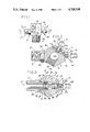
- FIG. 1 is a side elevation of a manifold fitting of this invention
- FIG. 2 is a transverse section on line 2--2 of FIG. 1;
- FIG. 3 is a transverse section on line 3--3 of FIG. 1;
- FIG. 4 is an enlarged vertical section on line 4--4 of FIG. 1 showing a filler valve
- FIG. 5 is a view illustrating a second embodiment of the invention.
- a manifold fitting of this invention is shown to comprise an elongate main body 3 of hexagonal cross-section, its six faces being designated 3a, 3b, 3c, 3d, 3e and 3f, and its ends being designated 4a and 4b.
- the body has a longitudinal passage 5 extending partway therethrough from end 4a toward end 4b, being of generally circular cross-section as shown in FIG. 2.
- Body 3 has an externally threaded first end portion 7 at the end 4b of the passage for attachment of the fitting 1 to a tank (not shown) for communication with the tank.
- the main body 3 further has threaded lateral openings 19, 21 and 25 therein, and one unthreaded opening 26 therein.
- the first lateral opening 19, which is an outlet opening, is in face 3e of the main body and has a threaded inner portion 19a and an unthreaded outer end counterbore 19b of slightly larger diameter than the inner portion 19a.
- the second lateral opening 21 is in face 3b opposite face 3e and in axial alignment with the outlet opening 19.
- the second opening 21 has a threaded outer portion 21a and an unthreaded inner end counterbore 21b of greater diameter than the outer portion 21a but of smaller diameter than portion 19a of opening 19.
- the third lateral opening 25 is in face 3d of the main body, of uniform diameter and threaded.
- the fourth lateral opening 26 is in face 3a and has an unthreaded inner end portion 26a, an unthreaded outer end counterbore 26b of greater diameter than the inner portion 26a, and an unthreaded intermediate portion 26c of diameter greater than the inner portion 26a and smaller than the outer end counterbore 26b. Face 3a is crimped about opening 26 so as to lessen the diameter of outer end counterbore 26b where it meets face 3a.
- the location of the openings along the body 3 is not crucial to the operation of this invention except that the outlet opening 19 and the second lateral opening 21 must be in axial alignment with each other.
- An outlet member 27 illustrated as being a nipple comprising a tubular body with a passage 29 therethrough, outer and inner threaded portions 31 and 33 and a hexagonal head 35 therebetween is adapted to be threaded in the first lateral opening 19 with the inner portion 33 in communication with passage 5.
- the diameter of the outer portion 31 of the outlet nipple 27 is greater than that of the inner end portion 33, and the outer portion 31 is adapted to threadably receive an air line for the flow of compressed air from the tank, through passages 5 and 29, and into the line.
- An O-ring seal 37 is provided on the inner portion of the nipple 27 adjacent its hexagonal head 35 to seal the outlet opening 19 at the junction of its inner and outer portions 19a and 19b when the outlet nipple 27 is threaded therein.
- the hexagonal head 35 is adapted to receive a suitable tool for tightening the outlet nipple in the opening 19.
- the outlet nipple 27 has a valve seat 39 at its inner end.
- a valve member 41 cooperable with the seat 39 is threadably fitted in the second lateral opening 21. It comprises a cylindrical stem with first and second rings 43 and 45 at the inner end thereof, third and fourth rings 47 and 49 intermediate its ends and a threaded outer end portion 51.
- An O-ring seal 53 disposed between the first and second rings 43 and 45 is adapted to engage the valve seat at the inner end of the outlet nipple 27 to block the passage of air through the outlet nipple, ring 43 being of smaller diameter than ring 45.
- a second O-ring seal 55 between the third and fourt rings 47 and 49 provides a slidable seal in the inner portion 21b of the second opening 21.
- the valve member 41 is threaded from the inside to the outside in the second lateral opening 21 and extends across the passage 5 with space therearound for the flow of air (see FIG. 3).
- the valve member 41 is adapted to be threaded inwardly in the second lateral opening 21 for engagement of the O-ring seal 53 with the valve seat 39 and outwardly with respect to the second lateral opening 21 to an open position for the flow of air from the tank through the passage 5 and through the outlet nipple passage 29.
- a knob 54 is attached to unthreaded portion 55 of the end of outer end portion 51 of valve member 41 for turning the member for inward and outward movement.
- Valve member 41 further comprises a stem passage 56 extending inwardly partway therethrough along its major axis from its outer end. Vents 56a, in valve member 41 allow air passage between stem passage 56 and axial passage 5 of main body 3.
- Filler check valve 57 is threaded in passage 56 for filling the tank with compressed air via application of a coupling at the end of a compressed air supply line (not shown).
- the check valve 57 as shown in FIG. 5, is of the conventional well-known type used for inflating tires, having a tubular body 58, a stem 59 therethrough and a spring (not shown) therein.
- the stem 59 has a valve member 60 for blocking the inner end of the body 58 and is held against the opening by the spring. Air is permitted to pass through the body and passage 56 of the valve member 41 by pressing inwardly on the outer portion 59a of the stem, thereby moving the valve member 60 away from the inner opening of the body and unblocking the passage through the check valve's body 58.
- a pressure relief safety valve 61 is incorporated within the lateral opening 26 in the main body 3. Opening 26 has an unthreaded inner end portion 26a, an unthreaded outer end counterbore 26b of slightly greater diameter than the inner portion 26a, and an unthreaded intermediate portion 26c of diameter greater than the inner portion 26a and smaller than the outer end counterbore 26b. Outwardly facing shoulder 26d is thereby formed between counterbore 26b and intermediate portion 26c. Inner portion 26a is formed to provide a valve seat 63 and having a passage 64 through said inner end portion (and seat) for flow of air to the intermediate portion 26c of valve 61.
- a closure head 65 is situated in the outer end counterbore 26b against shoulder 26d and held in place by a portion of metal of face 3a swaged about the periphery of opening 26 so as to lessen the diameter of outer end counterbore 26b where it meets face 3a.
- the closure head has a central opening 67.
- a stem 69 slidable in opening 67 has a valve member 71 at its inner end within the valve 61 engageable with the seat 63.
- Spring means 73 interposed between the valve member 71 and the closure 65 and biases the valve member 71 to its closed position engaging the seat.
- a cross passage through the manifold body 3 intersects opening 26 to form two lateral ports 77a, 77b extending through manifold body 3 in alignment with each other for the escape of air.
- Air is vented from the tank through ports 77a and 77b when the force of air on the valve head 71 exceeds the opening bias or on manually pulling the stem 69 by means of a ring 79 at the outer end of the stem 69.
- the main body further has the threaded lateral opening 25 adapted to receive a pressure gauge (not shown) for determining the pressure in the compressed air tank.
- a significant advantage of the manifold fitting of this invention is its flexibility so far as the manufacturer is concerned for supplying it in different configurations to suit users' different requirements.
- the manufacturer may supply the fitting with an outlet member at 27 having a female thread instead of the male thread at 31, the outlet member being threaded in the opening 19 and having a valve seat the same as at 39.
Abstract
Description
Claims (2)
Priority Applications (1)
| Application Number | Priority Date | Filing Date | Title |
|---|---|---|---|
| US07/081,753 US4768550A (en) | 1986-09-12 | 1987-08-05 | Manifold fitting for a compressed air tank |
Applications Claiming Priority (2)
| Application Number | Priority Date | Filing Date | Title |
|---|---|---|---|
| US06/906,389 US4705076A (en) | 1986-09-12 | 1986-09-12 | Manifold fitting for a compressed air tank |
| US07/081,753 US4768550A (en) | 1986-09-12 | 1987-08-05 | Manifold fitting for a compressed air tank |
Related Parent Applications (1)
| Application Number | Title | Priority Date | Filing Date |
|---|---|---|---|
| US06/906,389 Division US4705076A (en) | 1986-09-12 | 1986-09-12 | Manifold fitting for a compressed air tank |
Publications (1)
| Publication Number | Publication Date |
|---|---|
| US4768550A true US4768550A (en) | 1988-09-06 |
Family
ID=26765930
Family Applications (1)
| Application Number | Title | Priority Date | Filing Date |
|---|---|---|---|
| US07/081,753 Expired - Fee Related US4768550A (en) | 1986-09-12 | 1987-08-05 | Manifold fitting for a compressed air tank |
Country Status (1)
| Country | Link |
|---|---|
| US (1) | US4768550A (en) |
Cited By (8)
| Publication number | Priority date | Publication date | Assignee | Title |
|---|---|---|---|---|
| US4986297A (en) * | 1990-02-23 | 1991-01-22 | Control Devices, Inc. | Valve |
| US5127437A (en) * | 1990-02-23 | 1992-07-07 | Control Devices, Incorporated | Valve |
| US5244007A (en) * | 1992-11-25 | 1993-09-14 | Glave Eric C | Relief valve |
| US5967179A (en) * | 1998-02-02 | 1999-10-19 | Westinghouse Air Brake Company | Low profile discharge check valve |
| US20050057366A1 (en) * | 1999-12-08 | 2005-03-17 | Kadwell Brian J. | Compact particle sensor |
| EP1600674A1 (en) * | 2004-05-26 | 2005-11-30 | Luxembourg Patent Company S.A. | Valve for gas cylinder |
| US20060071189A1 (en) * | 2004-10-04 | 2006-04-06 | R. Conrader Company | Pressure relief valve |
| US20230039845A1 (en) * | 2021-08-09 | 2023-02-09 | Harry Lewellyn | Automatic deflator valves with vortex-like air flow with improved tire valve stem connection |
Citations (7)
| Publication number | Priority date | Publication date | Assignee | Title |
|---|---|---|---|---|
| US3001768A (en) * | 1957-01-22 | 1961-09-26 | Albert F Stevenson | Method and means for subjecting a liquid medium to violent vibrational pressure effects |
| US3145733A (en) * | 1960-07-07 | 1964-08-25 | Bastian Blessing Co | Swivel ring valve |
| US3198269A (en) * | 1963-03-21 | 1965-08-03 | Nickles Freddie Lee | Rotary drill bit nonreturn valve assembly |
| US3334697A (en) * | 1964-11-09 | 1967-08-08 | Tenneco Inc | Jet sub for drilling well bores |
| US3702141A (en) * | 1971-02-22 | 1972-11-07 | Dresser Ind | Gas type safety valve |
| US3796228A (en) * | 1972-08-25 | 1974-03-12 | A Bedo | Relief valve |
| US4574836A (en) * | 1984-11-15 | 1986-03-11 | Purolator Technologies Inc. | Bypass valve with indicator |
-
1987
- 1987-08-05 US US07/081,753 patent/US4768550A/en not_active Expired - Fee Related
Patent Citations (7)
| Publication number | Priority date | Publication date | Assignee | Title |
|---|---|---|---|---|
| US3001768A (en) * | 1957-01-22 | 1961-09-26 | Albert F Stevenson | Method and means for subjecting a liquid medium to violent vibrational pressure effects |
| US3145733A (en) * | 1960-07-07 | 1964-08-25 | Bastian Blessing Co | Swivel ring valve |
| US3198269A (en) * | 1963-03-21 | 1965-08-03 | Nickles Freddie Lee | Rotary drill bit nonreturn valve assembly |
| US3334697A (en) * | 1964-11-09 | 1967-08-08 | Tenneco Inc | Jet sub for drilling well bores |
| US3702141A (en) * | 1971-02-22 | 1972-11-07 | Dresser Ind | Gas type safety valve |
| US3796228A (en) * | 1972-08-25 | 1974-03-12 | A Bedo | Relief valve |
| US4574836A (en) * | 1984-11-15 | 1986-03-11 | Purolator Technologies Inc. | Bypass valve with indicator |
Cited By (10)
| Publication number | Priority date | Publication date | Assignee | Title |
|---|---|---|---|---|
| US4986297A (en) * | 1990-02-23 | 1991-01-22 | Control Devices, Inc. | Valve |
| US5127437A (en) * | 1990-02-23 | 1992-07-07 | Control Devices, Incorporated | Valve |
| US5244007A (en) * | 1992-11-25 | 1993-09-14 | Glave Eric C | Relief valve |
| US5967179A (en) * | 1998-02-02 | 1999-10-19 | Westinghouse Air Brake Company | Low profile discharge check valve |
| US20050057366A1 (en) * | 1999-12-08 | 2005-03-17 | Kadwell Brian J. | Compact particle sensor |
| EP1600674A1 (en) * | 2004-05-26 | 2005-11-30 | Luxembourg Patent Company S.A. | Valve for gas cylinder |
| US20050263192A1 (en) * | 2004-05-26 | 2005-12-01 | Paul Kremer | Tap for a gas or liquefied gas cylinder |
| US20060071189A1 (en) * | 2004-10-04 | 2006-04-06 | R. Conrader Company | Pressure relief valve |
| US20230039845A1 (en) * | 2021-08-09 | 2023-02-09 | Harry Lewellyn | Automatic deflator valves with vortex-like air flow with improved tire valve stem connection |
| US11642922B2 (en) * | 2021-08-09 | 2023-05-09 | Harry Lewellyn | Automatic deflator valves with vortex-like air flow with improved tire valve stem connection |
Similar Documents
| Publication | Publication Date | Title |
|---|---|---|
| US4613112A (en) | Quick-disconnect fitting for gas line connection | |
| JP4570368B2 (en) | Gas control assembly | |
| US3976110A (en) | Refrigerant charging kit | |
| US4616677A (en) | Manifold fitting for a compressed air tank | |
| KR100514761B1 (en) | Diaphragm valve | |
| US3698419A (en) | Devices for piercing tubes in closed pressure systems | |
| EP0023072B1 (en) | Filler valve for a liquefied gas tank | |
| US2412685A (en) | Conduit coupling | |
| US4281775A (en) | Can tapping valve apparatus | |
| US4768550A (en) | Manifold fitting for a compressed air tank | |
| US5560407A (en) | Dispensing tool assembly for evacuating and charging a fluid system | |
| US3791412A (en) | Reducing valve for high pressure fluids and connecting means therefor | |
| US2517669A (en) | Hose end | |
| US3788345A (en) | Devices for piercing tubes in closed pressure systems and for charging the latter | |
| US4705076A (en) | Manifold fitting for a compressed air tank | |
| US5657787A (en) | Gas pressure reducing regulator | |
| US3973584A (en) | Piercing valve for tapping pipelines | |
| US1355230A (en) | Pressure-release valve | |
| US3548861A (en) | Line tapping service valve | |
| US4852769A (en) | Refrigerant charging tool | |
| US4612962A (en) | Spring-loaded valve | |
| GB1599304A (en) | Inflation valve connectors | |
| US5492305A (en) | Connector assembly for connecting a source of fluid with a container to be filled | |
| US1588898A (en) | Quick opening and closing check valve for aerating systems | |
| US2854020A (en) | Tire valve inflation cap or extension |
Legal Events
| Date | Code | Title | Description |
|---|---|---|---|
| FEPP | Fee payment procedure |
Free format text: PAYOR NUMBER ASSIGNED (ORIGINAL EVENT CODE: ASPN); ENTITY STATUS OF PATENT OWNER: SMALL ENTITY |
|
| FPAY | Fee payment |
Year of fee payment: 4 |
|
| FPAY | Fee payment |
Year of fee payment: 8 |
|
| REMI | Maintenance fee reminder mailed | ||
| LAPS | Lapse for failure to pay maintenance fees | ||
| FP | Lapsed due to failure to pay maintenance fee |
Effective date: 20000906 |
|
| AS | Assignment |
Owner name: CDI ACQUISITION, LLC, MISSOURI Free format text: ASSIGNMENT OF ASSIGNORS INTEREST;ASSIGNOR:CDI HOLDCO, LLC;REEL/FRAME:019419/0408 Effective date: 20070607 Owner name: CDI HOLDCO, LLC, MISSOURI Free format text: ASSIGNMENT OF ASSIGNORS INTEREST;ASSIGNOR:CONTROL DEVICES, INCORPORATED;REEL/FRAME:019419/0394 Effective date: 20070607 |
|
| AS | Assignment |
Owner name: WACHOVIA CAPITAL FINANCE CORPORATION (CENTRAL), IL Free format text: SECURITY AGREEMENT;ASSIGNOR:CDI ACQUISITION, LLC;REEL/FRAME:019458/0670 Effective date: 20070611 |
|
| AS | Assignment |
Owner name: CONTROL DEVICES, LLC, MISSOURI Free format text: CHANGE OF NAME;ASSIGNOR:CDI ACQUISITION, LLC;REEL/FRAME:019588/0061 Effective date: 20070612 |
|
| AS | Assignment |
Owner name: CONTROL DEVICES, LLC, MISSOURI Free format text: RELEASE BY SECURED PARTY;ASSIGNOR:WELLS FARGO CAPITAL FINANCE, LLC;REEL/FRAME:031036/0506 Effective date: 20130819 |
|
| STCH | Information on status: patent discontinuation |
Free format text: PATENT EXPIRED DUE TO NONPAYMENT OF MAINTENANCE FEES UNDER 37 CFR 1.362 |