US4765693A - Valve assembly - Google Patents
Valve assembly Download PDFInfo
- Publication number
- US4765693A US4765693A US07/005,793 US579387A US4765693A US 4765693 A US4765693 A US 4765693A US 579387 A US579387 A US 579387A US 4765693 A US4765693 A US 4765693A
- Authority
- US
- United States
- Prior art keywords
- valve
- valves
- armature
- valve assembly
- embodied
- Prior art date
- Legal status (The legal status is an assumption and is not a legal conclusion. Google has not performed a legal analysis and makes no representation as to the accuracy of the status listed.)
- Expired - Fee Related
Links
- 239000012530 fluid Substances 0.000 claims abstract description 23
- 230000008878 coupling Effects 0.000 claims description 16
- 238000010168 coupling process Methods 0.000 claims description 16
- 238000005859 coupling reaction Methods 0.000 claims description 16
- 230000004888 barrier function Effects 0.000 claims description 8
- 230000008901 benefit Effects 0.000 abstract description 7
- 230000033228 biological regulation Effects 0.000 abstract description 3
- 238000007373 indentation Methods 0.000 description 18
- 125000006850 spacer group Chemical group 0.000 description 4
- 230000000694 effects Effects 0.000 description 3
- 230000009467 reduction Effects 0.000 description 3
- 230000000740 bleeding effect Effects 0.000 description 2
- 230000007423 decrease Effects 0.000 description 1
- 230000003247 decreasing effect Effects 0.000 description 1
- 230000003111 delayed effect Effects 0.000 description 1
- 239000000696 magnetic material Substances 0.000 description 1
- 238000012423 maintenance Methods 0.000 description 1
- 238000000034 method Methods 0.000 description 1
- 230000002265 prevention Effects 0.000 description 1
- 230000008569 process Effects 0.000 description 1
- 230000000644 propagated effect Effects 0.000 description 1
Images

Classifications
-
- B—PERFORMING OPERATIONS; TRANSPORTING
- B60—VEHICLES IN GENERAL
- B60T—VEHICLE BRAKE CONTROL SYSTEMS OR PARTS THEREOF; BRAKE CONTROL SYSTEMS OR PARTS THEREOF, IN GENERAL; ARRANGEMENT OF BRAKING ELEMENTS ON VEHICLES IN GENERAL; PORTABLE DEVICES FOR PREVENTING UNWANTED MOVEMENT OF VEHICLES; VEHICLE MODIFICATIONS TO FACILITATE COOLING OF BRAKES
- B60T8/00—Arrangements for adjusting wheel-braking force to meet varying vehicular or ground-surface conditions, e.g. limiting or varying distribution of braking force
- B60T8/32—Arrangements for adjusting wheel-braking force to meet varying vehicular or ground-surface conditions, e.g. limiting or varying distribution of braking force responsive to a speed condition, e.g. acceleration or deceleration
- B60T8/34—Arrangements for adjusting wheel-braking force to meet varying vehicular or ground-surface conditions, e.g. limiting or varying distribution of braking force responsive to a speed condition, e.g. acceleration or deceleration having a fluid pressure regulator responsive to a speed condition
- B60T8/36—Arrangements for adjusting wheel-braking force to meet varying vehicular or ground-surface conditions, e.g. limiting or varying distribution of braking force responsive to a speed condition, e.g. acceleration or deceleration having a fluid pressure regulator responsive to a speed condition including a pilot valve responding to an electromagnetic force
- B60T8/3615—Electromagnetic valves specially adapted for anti-lock brake and traction control systems
- B60T8/363—Electromagnetic valves specially adapted for anti-lock brake and traction control systems in hydraulic systems
- B60T8/364—Electromagnetic valves specially adapted for anti-lock brake and traction control systems in hydraulic systems switching between a number of discrete positions as a function of the applied signal, e.g. 3/3-valves
-
- B—PERFORMING OPERATIONS; TRANSPORTING
- B60—VEHICLES IN GENERAL
- B60T—VEHICLE BRAKE CONTROL SYSTEMS OR PARTS THEREOF; BRAKE CONTROL SYSTEMS OR PARTS THEREOF, IN GENERAL; ARRANGEMENT OF BRAKING ELEMENTS ON VEHICLES IN GENERAL; PORTABLE DEVICES FOR PREVENTING UNWANTED MOVEMENT OF VEHICLES; VEHICLE MODIFICATIONS TO FACILITATE COOLING OF BRAKES
- B60T8/00—Arrangements for adjusting wheel-braking force to meet varying vehicular or ground-surface conditions, e.g. limiting or varying distribution of braking force
- B60T8/32—Arrangements for adjusting wheel-braking force to meet varying vehicular or ground-surface conditions, e.g. limiting or varying distribution of braking force responsive to a speed condition, e.g. acceleration or deceleration
- B60T8/34—Arrangements for adjusting wheel-braking force to meet varying vehicular or ground-surface conditions, e.g. limiting or varying distribution of braking force responsive to a speed condition, e.g. acceleration or deceleration having a fluid pressure regulator responsive to a speed condition
- B60T8/36—Arrangements for adjusting wheel-braking force to meet varying vehicular or ground-surface conditions, e.g. limiting or varying distribution of braking force responsive to a speed condition, e.g. acceleration or deceleration having a fluid pressure regulator responsive to a speed condition including a pilot valve responding to an electromagnetic force
- B60T8/3615—Electromagnetic valves specially adapted for anti-lock brake and traction control systems
- B60T8/363—Electromagnetic valves specially adapted for anti-lock brake and traction control systems in hydraulic systems
- B60T8/365—Electromagnetic valves specially adapted for anti-lock brake and traction control systems in hydraulic systems combining a plurality of functions in one unit, e.g. pressure relief
-
- B—PERFORMING OPERATIONS; TRANSPORTING
- B60—VEHICLES IN GENERAL
- B60T—VEHICLE BRAKE CONTROL SYSTEMS OR PARTS THEREOF; BRAKE CONTROL SYSTEMS OR PARTS THEREOF, IN GENERAL; ARRANGEMENT OF BRAKING ELEMENTS ON VEHICLES IN GENERAL; PORTABLE DEVICES FOR PREVENTING UNWANTED MOVEMENT OF VEHICLES; VEHICLE MODIFICATIONS TO FACILITATE COOLING OF BRAKES
- B60T8/00—Arrangements for adjusting wheel-braking force to meet varying vehicular or ground-surface conditions, e.g. limiting or varying distribution of braking force
- B60T8/32—Arrangements for adjusting wheel-braking force to meet varying vehicular or ground-surface conditions, e.g. limiting or varying distribution of braking force responsive to a speed condition, e.g. acceleration or deceleration
- B60T8/34—Arrangements for adjusting wheel-braking force to meet varying vehicular or ground-surface conditions, e.g. limiting or varying distribution of braking force responsive to a speed condition, e.g. acceleration or deceleration having a fluid pressure regulator responsive to a speed condition
- B60T8/50—Arrangements for adjusting wheel-braking force to meet varying vehicular or ground-surface conditions, e.g. limiting or varying distribution of braking force responsive to a speed condition, e.g. acceleration or deceleration having a fluid pressure regulator responsive to a speed condition having means for controlling the rate at which pressure is reapplied to or released from the brake
- B60T8/5018—Pressure reapplication using restrictions
- B60T8/5025—Pressure reapplication using restrictions in hydraulic brake systems
-
- Y—GENERAL TAGGING OF NEW TECHNOLOGICAL DEVELOPMENTS; GENERAL TAGGING OF CROSS-SECTIONAL TECHNOLOGIES SPANNING OVER SEVERAL SECTIONS OF THE IPC; TECHNICAL SUBJECTS COVERED BY FORMER USPC CROSS-REFERENCE ART COLLECTIONS [XRACs] AND DIGESTS
- Y10—TECHNICAL SUBJECTS COVERED BY FORMER USPC
- Y10T—TECHNICAL SUBJECTS COVERED BY FORMER US CLASSIFICATION
- Y10T137/00—Fluid handling
- Y10T137/8593—Systems
- Y10T137/87169—Supply and exhaust
- Y10T137/87217—Motor
Definitions
- the invention is based on a valve assembly as set forth hereinafter.
- a valve assembly suitable for an anti-skid brake system which includes two valves, actuatable in succession, having valve seats and valve balls, and which has an electromagnet having an armature and at least one restoring spring engaging it and at least one barrier spring.
- the valve assembly has the advantage that it enables a desired retardation of automatic brake pressure increases in a space-saving manner, at low engineering cost.
- the provisions recited herein disclose advantageous features of and improvements to the valve assembly disclosed.
- the new characteristics disclose an advantageous combination for vehicle brake systems.
- the characteristics have the advantage, for instance inside a vehicle brake system, that whenever the particular connection is joined to a brake pressure transducer, technologically simple control of the rates of increase of brake pressures is effected in at least one wheel brake as a function of pressure differences between the master cylinder connection and the wheel brake connection.
- a conventionally embodied control unit such as that used in the previously known valve assembly according to U.S. Pat. No. 3,989,063, is adequate.
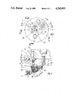
- FIG. 1 is a cross section taken through the valve assembly according to the invention
- FIG. 2 is a first longitudinal section through the valve assembly of FIG. 1;
- FIG. 3 is a partial second longitudinal section through the valve assembly of FIG. 1.
- the valve assembly 2 has a housing 3 that together with a coil 4 forms an electromagnet 5, a linear armature 6 that is movable in the electromagnet 5, two restoring springs 7, 8, a barrier spring 9 and three valves 10, 11 and 12 accommodated in the housing 3.
- connection indentation 13 Belonging to the valves is a connection indentation 13 that begins at an upper end face 3a of the housing 3.
- This connection indentation 13 is joined via a connecting part 14 with a so-called brake pressure transducer connection 15.
- this brake pressure transducer connection 15 may be connected to a brake pressure control valve or a master brake cylinder and a return pump or a brake pressure feeding apparatus.
- Two parallel-oriented chambers 16 and 17 originate at the connection indentation 13 and terminate at valve seats 18, 19. From the valve seats 18, 19, connecting bores 20, 21 lead to an armature chamber 22.
- the armature 6 is displaceable inside this armature chamber 22.
- valves 10 and 11 Opposite from these valves 10, 11 and 12, the housing 3 is closed by means of a magnet core 23.
- the valves 10 and 11 have valve elements 24 and 25 embodied as balls.
- Closing springs 26 and 27 are disposed inside the chambers 16 and 17, urging the valve elements 24 and 25 toward their valve seats 18 and 19. Because of the closing springs 26 and 27, the valves 10 and 11 act as check valves whenever higher pressure prevail in the connecting bores 20 and 21 than in the chambers 16 and 17 and whenever no opening forces, to be described below, lift the valve elements 24 and 25.
- the chambers 16 and 17 are partly closed by ring disks 28 and 29.
- One end of closing springs 26 and 27 are supported on these ring disks 28 and 29.
- the ring disks 28 and 29 are secured in their position shown, by bracing, for example.
- the ring disks 28 and 29 have holes 30 and 31, each of which act as throttle openings, to a variable extent depending on their diameter.
- a coupling element in the form of an opening tappet 32 is oriented in the extension of the longitudinal axis of the connecting bore 20.
- a coupling element embodied in the form of an opening tappet 33 is also located in the extension of the connecting bore 21.
- This opening tappet 33 extends longitudinally displaceably into a guide bore 34 located in the armature 6.
- This guide bore 34 additionally receives a spring 36 in a pre-stressed state, which presses against a collar 36 disposed on the opening tappet 33.
- a perforated disk 38 secured to the end 37 of the armature 6 serves as a stop for the collar 36 to prevent it from being pushed out of the armature 6 by the force of the spring 35.
- the valve 12 comprises a valve seat 39, beginning at the armature chamber 22; an associated valve element 40, which is embodied as a ball; and a rodlike coupling element 41. Originating at the valve seat 39 is a connecting bore 42, which communicates via further bores 43 and 44 with a connection indentation 45.
- the connection indentation 45 is part of a so-called relief connection, which depending on the embodiment of the brake system may for instance communicate with a return container or directly with a return pump.
- connection indentation 47 is for example part of a wheel brake connection 48.
- the rodlike coupling element 41 is extended through the perforated disk 38 and has a collar 49 inside the armature 6.
- the armature 6 Coaxially with the coupling element 41, the armature 6 has a receiving bore 50 for the barrier spring 9 and a stop ring 51, which is displaceable inside the receiving bore 50 and has an annular attachment 52, which is located between the barrier spring 9 and the collar 49.
- a spacer ring 53 is inserted between the stop ring 51 and the perforated disk 38.
- the receiving bore 50 is contiguous with a bore 54 that has a smaller diameter than the receiving bore 50. Extending through this bore 54 is a tappet 55 that is displaceable relative to the armature 6 and has an unattached collar 56 inside the receiving bore 50.
- the collar 56 forms an ahutment that is movable relative to the stop ring 51.
- the barrier spring 9 is supported on the collar 56.
- the tappet 55 In the basic position of the armature 6, the tappet 55 is spaced apart from the magnet core 23, which forms an abutment for this tappet 55 in a manner to be described below.
- the bore 54 is adjoined by a receiving bore 57, which has a larger diameter than the bore 54 and receives the restoring spring 7.
- the restoring spring 7 is embodied as a helical spring and is installed in the pre-stressed state, being supported on the restoring spring 8, which in turn rests on the magnet core 23.
- the restoring spring 8 is made of an anti-magnetic material in the form of a spring washer.
- the lengths of the opening tappets 32 and 33 are selected such that in the basic position of the armature 6 shown, the valve elements 24 and 25 are raised from their valve seats 18 and 19 counter to the forces of the closing springs 26 and 27.
- the closing spring 27 and the spring 35 are matched to one another such that whenever the same pressure prevails in both the connection indentation 13 and the armature chamber 22, the collar 36 of the opening tappet 33 rests on the perforated disk 38, which acts as a stop in the manner already described.
- connection indentation 47 which is for instance associated with a wheel brake connection 48.
- the armature 6 compresses the restoring spring 7 further, and in so doing compresses the restoring spring 8 until finally it is virtually flat.
- the armature 6 also overcomes the force of the pre-stressed barrier spring 9, so that the perforated disk 38 connected to the armature 6 acts upon the collar 49 via the spacer ring 53, overcoming the force of the spring 9a, and as a result, via the rodlike coupling element 41, pulls the valve element 40 away from its valve seat 39.
- the armature chamber 22 is thereby made to communicate with the connection indentation 45.
- valve assembly 2 Given the typical pressure differences, brake pressure rises are delayed during anti-skid braking regulation, while contrarily with small pressure differences between the connection indentation 13 and the armature chamber 22, there is a comparatively largely unthrottled flow through the valve assembly 2. As a result, it is possible to build up brake pressures in wheel brakes relatively without hindrance upon actuation of the brake pedal transducer, for instance by means of a brake pedal.
- valve 11 serves to cause the maximum possible quantities of pressure fluid to flow through the valve assembly 2 during normal braking, and to allow the brake pressure desired by the driver to become effective in the wheel without delay.
- a hole 31 disposed in the associated ring disk 29 is embodied only large enough that the remaining annular cross section serves substantially only to support the closing spring 27.
- the diameter of the hole 30 in the ring disk 38 is selected to be so narrow that even with a large pressure difference between the connection indentation 13 and the armature chamber 22, only a desirably slow pressure rise takes place in the associated wheel brake.
- the size of the valve element 24, the valve seat 18 and an inside cross section between the connecting bore 20 and the opening tappet 32 are selected such that with a large hole 30, a desired minimum throughput of pressure fluid comes about.
- the throttling is thus preferably accomplished by embodying the ring disk 28 as a throttle. It is then possible to adapt to required pressure fluid throughputs per unit of time by exchanging the ring disk 28 for a disk having some other hole diameter.
- the basic concept of the invention is directed to varying the rates of pressure rise in a pressure receiver, which may for example be the wheel brake mentioned several times above. To apply this basic concept, it is accordingly unnecessary to include a pressure reduction valve 12 in the valve assembly 2. As in the prior art, such a valve 12 intended for decreasing pressure can also be disposed outside the valve assembly as a separate valve. There are examples of this in the prior art.
- the valve assembly 2 is shown in FIGS. 2 and 3 in its installed position in which it is used.
- the connection indentations 13, 45 and 47 and the valves 10, 11, 12 are located above the armature chamber 22. This has the advantage that when the armature chamber 22 is being filled with pressure fluid, bleeding is attainable without requiring complicated constructonal provisions.
Applications Claiming Priority (2)
| Application Number | Priority Date | Filing Date | Title |
|---|---|---|---|
| DE19863607693 DE3607693A1 (de) | 1986-03-08 | 1986-03-08 | Ventilanordnung |
| DE3607693 | 1986-03-08 |
Publications (1)
| Publication Number | Publication Date |
|---|---|
| US4765693A true US4765693A (en) | 1988-08-23 |
Family
ID=6295851
Family Applications (1)
| Application Number | Title | Priority Date | Filing Date |
|---|---|---|---|
| US07/005,793 Expired - Fee Related US4765693A (en) | 1986-03-08 | 1987-01-21 | Valve assembly |
Country Status (4)
| Country | Link |
|---|---|
| US (1) | US4765693A (de) |
| JP (1) | JPS62218255A (de) |
| DE (1) | DE3607693A1 (de) |
| FR (1) | FR2604236B1 (de) |
Cited By (11)
| Publication number | Priority date | Publication date | Assignee | Title |
|---|---|---|---|---|
| US4859005A (en) * | 1986-07-26 | 1989-08-22 | Eaton Corporation | Three-port fluid valve |
| US4919497A (en) * | 1987-08-04 | 1990-04-24 | Robert Bosch Gmbh | Tests of electrohydraulic switching valves with fluidic ball elements |
| US4938545A (en) * | 1989-03-13 | 1990-07-03 | General Motors Corporation | ABS solenoid/isolation valve integration into single-ended solenoid body, using pump pressure actuation |
| US5141298A (en) * | 1988-05-17 | 1992-08-25 | Alfred Teves Gmbh | Hydraulic unit for a braking pressure regulating device |
| EP0595014A1 (de) * | 1992-10-29 | 1994-05-04 | Robert Bosch Gmbh | Magnetventil |
| US5556175A (en) * | 1992-10-30 | 1996-09-17 | Nippondenso Co., Ltd. | Solenoid valve with ball attracted towards seating because of negative pressure |
| US5685337A (en) * | 1995-08-18 | 1997-11-11 | Daewoo Electronics Co., Ltd. | Solenoid valve with a hinged structure |
| US5730509A (en) * | 1995-08-23 | 1998-03-24 | Robert Bosch Gmbh | Magnetic control valve for a slip-controlled hydraulic brake system for motor vehicles |
| US5738142A (en) * | 1996-08-09 | 1998-04-14 | Case Corporation | Pressure holding directional control valve |
| US6814409B2 (en) | 2001-04-12 | 2004-11-09 | A-Dec, Inc. | Hydraulic drive system |
| CN103003112A (zh) * | 2010-07-14 | 2013-03-27 | 罗伯特·博世有限公司 | 电磁阀以及具有这种阀的驾驶员辅助装置 |
Families Citing this family (9)
| Publication number | Priority date | Publication date | Assignee | Title |
|---|---|---|---|---|
| JPH0636372Y2 (ja) * | 1988-04-01 | 1994-09-21 | 株式会社ゼクセル | 電磁弁 |
| DE4134427A1 (de) * | 1991-10-18 | 1993-04-22 | Teves Gmbh Alfred | Blockiergeschuetzte hydraulische bremsanlage |
| US5522426A (en) * | 1992-09-11 | 1996-06-04 | Itt Automotive Europe Gmbh | Valve arrangement in particular a solenoid valve arrangement for slip-controlled automotive vehicle brake systems |
| DE4230393A1 (de) * | 1992-09-11 | 1994-03-17 | Teves Gmbh Alfred | Ventilanordnung, insbesondere Elektromagnetventilanordnung für schlupfgeregelte Kraftfahrzeugbremsanlagen |
| DE4236047A1 (de) * | 1992-10-24 | 1994-04-28 | Teves Gmbh Alfred | Bremsanlage mit Blockierschutz- und/oder Antriebsschlupfregelung |
| DE4332372A1 (de) * | 1993-09-23 | 1995-03-30 | Bosch Gmbh Robert | Elektromagnetisch betätigbares Ventil, insbesondere für schlupfgeregelte hydraulische Bremsanlagen in Kraftfahrzeugen |
| DE4332368A1 (de) * | 1993-09-23 | 1995-03-30 | Bosch Gmbh Robert | Elektromagnetisch betätigbares Ventil, insbesondere für schlupfgeregelte hydraulische Bremsanlagen in Kraftfahrzeugen |
| DE4427800A1 (de) * | 1994-08-05 | 1996-02-08 | Teves Gmbh Alfred | Hydraulische Bremsanlage mit Radschlupfregelung |
| DE102010040631A1 (de) * | 2010-09-13 | 2012-03-15 | Robert Bosch Gmbh | Stromlos geschlossenes Magnetventil |
Citations (7)
| Publication number | Priority date | Publication date | Assignee | Title |
|---|---|---|---|---|
| US3989063A (en) * | 1974-01-26 | 1976-11-02 | Robert Bosch G.M.B.H. | Electromagnetic 3-way valve |
| US4138165A (en) * | 1977-05-10 | 1979-02-06 | Blomberg Folke Ivar | Brake anti-locking modulator with reapplication control |
| US4141595A (en) * | 1975-07-15 | 1979-02-27 | Robert Bosch Gmbh | Anti-wheel-lock or anti-skid system for motor vehicles |
| US4155603A (en) * | 1976-12-15 | 1979-05-22 | Girling Limited | Anti-skid vehicle braking systems |
| US4422695A (en) * | 1981-01-14 | 1983-12-27 | Lucas Industries Limited | Anti-skid braking system for vehicles |
| FR2569382A1 (fr) * | 1984-08-25 | 1986-02-28 | Bosch Gmbh Robert | Procede pour le fonctionnement d'une installation de freinage de vehicule a systeme antiblocage et installation de freinage pour sa mise en oeuvre |
| US4640558A (en) * | 1983-07-29 | 1987-02-03 | Toyota Jidosha Kabushiki Kaisha | Anti-skid brake system |
Family Cites Families (8)
| Publication number | Priority date | Publication date | Assignee | Title |
|---|---|---|---|---|
| DE1102513B (de) * | 1952-10-08 | 1961-03-16 | Siam | Magnetsteuerventil |
| FR1598822A (de) * | 1968-12-27 | 1970-07-06 | ||
| JPS5541936B2 (de) * | 1973-06-01 | 1980-10-27 | ||
| US3963048A (en) * | 1975-02-27 | 1976-06-15 | General Gas Light Company | Poppet valve assembly |
| DE2631346A1 (de) * | 1976-07-13 | 1978-01-19 | Bosch Gmbh Robert | Blockierschutzeinrichtung fuer druckluftbetaetigte bremsen eines kraftfahrzeugs |
| DE3001654A1 (de) * | 1980-01-17 | 1981-07-23 | G.L. Rexroth Gmbh, 8770 Lohr | Hydraulische anhaenger-bremsanlage |
| FR2505281A1 (fr) * | 1981-05-08 | 1982-11-12 | Dba | Modulateur de freinage pour systeme de freinage anti-patinant |
| DE3421787A1 (de) * | 1983-06-14 | 1985-01-24 | Robert Bosch Gmbh, 7000 Stuttgart | Antiblockierregelsystem |
-
1986
- 1986-03-08 DE DE19863607693 patent/DE3607693A1/de not_active Withdrawn
-
1987
- 1987-01-21 US US07/005,793 patent/US4765693A/en not_active Expired - Fee Related
- 1987-03-05 FR FR8702990A patent/FR2604236B1/fr not_active Expired - Lifetime
- 1987-03-06 JP JP62050451A patent/JPS62218255A/ja active Pending
Patent Citations (7)
| Publication number | Priority date | Publication date | Assignee | Title |
|---|---|---|---|---|
| US3989063A (en) * | 1974-01-26 | 1976-11-02 | Robert Bosch G.M.B.H. | Electromagnetic 3-way valve |
| US4141595A (en) * | 1975-07-15 | 1979-02-27 | Robert Bosch Gmbh | Anti-wheel-lock or anti-skid system for motor vehicles |
| US4155603A (en) * | 1976-12-15 | 1979-05-22 | Girling Limited | Anti-skid vehicle braking systems |
| US4138165A (en) * | 1977-05-10 | 1979-02-06 | Blomberg Folke Ivar | Brake anti-locking modulator with reapplication control |
| US4422695A (en) * | 1981-01-14 | 1983-12-27 | Lucas Industries Limited | Anti-skid braking system for vehicles |
| US4640558A (en) * | 1983-07-29 | 1987-02-03 | Toyota Jidosha Kabushiki Kaisha | Anti-skid brake system |
| FR2569382A1 (fr) * | 1984-08-25 | 1986-02-28 | Bosch Gmbh Robert | Procede pour le fonctionnement d'une installation de freinage de vehicule a systeme antiblocage et installation de freinage pour sa mise en oeuvre |
Cited By (13)
| Publication number | Priority date | Publication date | Assignee | Title |
|---|---|---|---|---|
| US4859005A (en) * | 1986-07-26 | 1989-08-22 | Eaton Corporation | Three-port fluid valve |
| US4919497A (en) * | 1987-08-04 | 1990-04-24 | Robert Bosch Gmbh | Tests of electrohydraulic switching valves with fluidic ball elements |
| US5141298A (en) * | 1988-05-17 | 1992-08-25 | Alfred Teves Gmbh | Hydraulic unit for a braking pressure regulating device |
| US4938545A (en) * | 1989-03-13 | 1990-07-03 | General Motors Corporation | ABS solenoid/isolation valve integration into single-ended solenoid body, using pump pressure actuation |
| EP0595014A1 (de) * | 1992-10-29 | 1994-05-04 | Robert Bosch Gmbh | Magnetventil |
| US5356211A (en) * | 1992-10-29 | 1994-10-18 | Robert Bosch Gmbh | Magnet valve |
| US5556175A (en) * | 1992-10-30 | 1996-09-17 | Nippondenso Co., Ltd. | Solenoid valve with ball attracted towards seating because of negative pressure |
| US5685337A (en) * | 1995-08-18 | 1997-11-11 | Daewoo Electronics Co., Ltd. | Solenoid valve with a hinged structure |
| US5730509A (en) * | 1995-08-23 | 1998-03-24 | Robert Bosch Gmbh | Magnetic control valve for a slip-controlled hydraulic brake system for motor vehicles |
| US5738142A (en) * | 1996-08-09 | 1998-04-14 | Case Corporation | Pressure holding directional control valve |
| US6814409B2 (en) | 2001-04-12 | 2004-11-09 | A-Dec, Inc. | Hydraulic drive system |
| CN103003112A (zh) * | 2010-07-14 | 2013-03-27 | 罗伯特·博世有限公司 | 电磁阀以及具有这种阀的驾驶员辅助装置 |
| US20130200283A1 (en) * | 2010-07-14 | 2013-08-08 | Robert Bosch Gmbh | Solenoid Valve and Driver Assistance Device having such a Valve |
Also Published As
| Publication number | Publication date |
|---|---|
| FR2604236B1 (fr) | 1990-09-28 |
| DE3607693A1 (de) | 1987-09-10 |
| FR2604236A1 (fr) | 1988-03-25 |
| JPS62218255A (ja) | 1987-09-25 |
Similar Documents
| Publication | Publication Date | Title |
|---|---|---|
| US4765693A (en) | Valve assembly | |
| US4844119A (en) | Integrated three-way and isolation solenoid valve | |
| US5356211A (en) | Magnet valve | |
| JP3030074B2 (ja) | 電磁作動弁 | |
| US4589706A (en) | Vehicle brake system for controlling wheel brake slippage and wheel drive slippage | |
| US4634190A (en) | Hydraulic brake system with slip control | |
| US5333945A (en) | Brake pressure control apparatus | |
| US4840434A (en) | Vehicle brake system having an anti-skid apparatus | |
| US4662687A (en) | Anti-skid brake system and anti-drive-slip system | |
| CA1265172A (en) | Integrated three way and isolation solenoid valve | |
| JPH04293648A (ja) | 油圧ブレーキ装置 | |
| US3617098A (en) | Inlet vlave for antilocking brake control system | |
| US4655512A (en) | Brake system having a brake booster | |
| US5267785A (en) | Method for switching a pressure control device | |
| US5681098A (en) | Anti-locking brake system with a switchable orifice control valve | |
| US5641211A (en) | Pressure control valve for hydraulic slip-controlled brake system | |
| US5163474A (en) | Combination solenoid valve and integral shuttle valve | |
| US3950035A (en) | Relay valve operated skid control system | |
| JPS611569A (ja) | 液圧的なブレーキ圧制御弁 | |
| US4571944A (en) | Blow-off valve in a quick take-up master cylinder | |
| US4982999A (en) | Adaptive braking system default activated proportioning valve | |
| US4198099A (en) | Braking pressure control unit for vehicular hydraulic brake systems | |
| US5251969A (en) | Brake power controller with electrically actuated locking apparatus | |
| US5050382A (en) | Tandem master cylinder for hydraulic brake systems | |
| GB2179109A (en) | Vehicular hydraulic brake system with anti-lock control |
Legal Events
| Date | Code | Title | Description |
|---|---|---|---|
| AS | Assignment |
Owner name: ROBERT BOSCH, STUTTGART, GERMANY Free format text: ASSIGNMENT OF ASSIGNORS INTEREST.;ASSIGNOR:STEGMAIER, ALWIN;REEL/FRAME:004691/0767 Effective date: 19870107 |
|
| FEPP | Fee payment procedure |
Free format text: PAYOR NUMBER ASSIGNED (ORIGINAL EVENT CODE: ASPN); ENTITY STATUS OF PATENT OWNER: LARGE ENTITY |
|
| REMI | Maintenance fee reminder mailed | ||
| LAPS | Lapse for failure to pay maintenance fees | ||
| FP | Lapsed due to failure to pay maintenance fee |
Effective date: 19920823 |
|
| STCH | Information on status: patent discontinuation |
Free format text: PATENT EXPIRED DUE TO NONPAYMENT OF MAINTENANCE FEES UNDER 37 CFR 1.362 |