US4761580A - Magnetic top wedge - Google Patents
Magnetic top wedge Download PDFInfo
- Publication number
- US4761580A US4761580A US07/063,264 US6326487A US4761580A US 4761580 A US4761580 A US 4761580A US 6326487 A US6326487 A US 6326487A US 4761580 A US4761580 A US 4761580A
- Authority
- US
- United States
- Prior art keywords
- improvement
- stack
- laminations
- lamination
- wedge
- Prior art date
- Legal status (The legal status is an assumption and is not a legal conclusion. Google has not performed a legal analysis and makes no representation as to the accuracy of the status listed.)
- Expired - Fee Related
Links
Images


Classifications
-
- H—ELECTRICITY
- H02—GENERATION; CONVERSION OR DISTRIBUTION OF ELECTRIC POWER
- H02K—DYNAMO-ELECTRIC MACHINES
- H02K3/00—Details of windings
- H02K3/46—Fastening of windings on the stator or rotor structure
- H02K3/48—Fastening of windings on the stator or rotor structure in slots
- H02K3/487—Slot-closing devices
- H02K3/493—Slot-closing devices magnetic
Definitions
- the present invention overcomes the shortcomings of the prior art by providing for a magnetic slot wedge having insulation of predetermined thickness between the wedge laminations and the stator laminations. Additionally, means are provided for aligning wedge laminations in a simple and efficient manner, thus reducing manufacturing costs.
- FIG. 1 is a partial elevation view of a prior art lamination having a semi-closed slot.
- FIG. 2 is a partial elevation view of a prior art lamination having a fully open slot receiving form wound coils secured by non-magnetic top wedges.
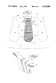
- FIG. 3 shows an embodiment of the present invention useful in connection with form wound coils in fully open slots.
- FIG. 4 shows an embodiment of the present invention.
- FIG. 5 shows the embodiment of FIG. 4 in more detail.
- FIG. 6 shows a further feature of the present invention as being a filament running through the magnetic laminations to enable alignment of the laminations.
- FIG. 7 shows an exploded view of the aligned laminations and insulating carrier.
- FIG. 8 shows a plan view of one embodiment of the laminations of the present invention.
- FIG. 9 shows an alternative embodiment of the magnetic top wedge of the present invention suitable for use in the stator of FIG. 2.
- a portion of a dynamo electric machine 18 may be seen having a core structure 20 made up of a plurality of laminations 22 each having a plurality of slots 24.
- Each slot 24 has walls 26 and has a keyed configuration 28 to receive a wedge 30 to retain a coil 32 in the slot.
- tapered wall slots 34 may be formed in core 36.
- Coils 38, 40 may be random wound. Coils 38 and 40 are insulated from core 36 as follows.
- a slot cell layer of insulation 42 is inserted into slot 34.
- a filler material 44 preferably of a material receptive to resin impregnation forms a bottom filler 44.
- Magnet wires 46 are inserted into slot 34 to form coil 40.
- a center filler 48 and center wedge 50 are placed over coil 40 to separate coil 40 from coil 38.
- a top filler 52 and top U-wedge 54 are placed over coil 38.
- Coils 38 and 40 are preferably vacuum pressure impregnated with an appropriate insulating resin which also impregnates the filler material 44.
- the magnetic top wedge 30 is placed over this assembly at the entrance to slot 34. Alternatively, wedge 30 may be placed at the entrance to slot 24, if form wound coils are desired to be utilized.
- a plurality of ferromagnetic laminations 56 are formed into a stack 58.
- Stack 58 is contained within an insulating carrier 60 which may be a hollow extruded plastic channel, for example. Channel or carrier 60 may be sealed at each end by conventional means, such as heat staking.
- stack 58 may be encapsulated in a plastic or epoxy supporting and enclosing stack 58 in a final shape 60 suitable for insertion into the entry of core slot 34.
- Lamination 56 forms an extension of the magnetic path across the entry 62 of slot 34.
- Lamination 56 is insulated from core 36 by carrier 60.
- Carrier 60 is preferably formed of a plastic such as Union Carbide Polysulfone P1720NT13 or Dupont Rynite FR530, however, any material compatible with the manufacturing and operating environment of the machinery in which wedge 30 is to be used may be selected.
- laminations 56 provide an extension of the magnetic path across the slot opening 62, while at the same time providing for a magnetic gap of predetermined length, preferably equal to two times the thickness of insulating layer 64 which is interposed between each side of the stack 58 and the wall 66 of the slot opening 62. It is to be understood that the magnetic gap formed by layers 64 preferably corresponds to gap 10 in semi-closed slot 8.
- lamination 56 will have a center of gravity 68 located by intersecting axis 70, 72.
- Lamination 58 is further formed to include a notch or opening 74, preferably formed as a keyhole slot. Opening 74 is located in lamination 56 spaced apart from center of gravity 68.
- a plurality of laminations 56 are threaded onto a filament 76 which may have a deformed or enlarged end 78.
- Laminations 56 are threaded onto filament 76 by way of notch 74, which in this embodiment is in the form of a keyhole opening.
- filament 76 which may be a wire or a non-metallic member
- laminations 56 will form into a congruent stack 58 due to the action of gravity.
- filaments 56 Once filaments 56 are formed into such a congruent stack, they may be inserted into carrier 60, or impregnated and encapsulated as has been previously described. If metallic, filament 76 is preferably removed from stack 58. If filament 76 is non-magnetic, it may be left in stack 58 or withdrawn.
- wedge laminations 80 may be formed to have a side configuration 82 keyed to conform to a slot opening as shown in FIG. 2.
- insulating layer 84 is interposed between side 82 and an adjacent side of a core lamination wall.
- the function of opening 74 may be accomplished by a hole or aperture 86 which itself is displaced from the center of gravity the cross-section of lamination 80.
Landscapes
- Engineering & Computer Science (AREA)
- Power Engineering (AREA)
- Insulation, Fastening Of Motor, Generator Windings (AREA)
- Manufacture Of Motors, Generators (AREA)
Abstract
A magnetic top wedge for dynamoelectric machinery core slots is disclosed having laminated ferromagnetic segments aligned by an eccentric aperture and enclosed in an electrically insulating and spacing carrier.
Description
In the past, it had been found desirable to build motors using semi-closed slots 10 (see FIG. 1) in stator laminations 12 to improve motor performance. This necessarily resulted in increased difficulty in manufacturing motors, particularly in inserting windings into the stator slots because of the reduced accessibility of the slot with a semi-closed entry. One solution was to provide for fully open slots, with greater ease of coil insertion which permitted form wound coils 14 (see FIG. 2) but resulted in a reduction in motor performance when used with top wedges 18 without magnetic properties.
Various efforts have been undertaken to provide magnetic slot wedges with wire or iron powder or fillings imbedded in a carrier. Each of these approaches has, however, failed to approach the performance obtainable with a semi-closed slot design.
More recently, efforts have been undertaken to provide magnetic wedges formed of laminated magnetic material with the wedge laminations directly abutting stator laminations in the slot as exemplified by U.S. Pat. No. 4,425,521 for a magnetic slot wedge with low average permeability and high mechanical strength. Such an approach, however, suffers from the disability that stator laminations may be short circuited at the stator-wedge interface when the wedge laminations are offset from the stator laminations as may readily occur in practice. Such short circuits at the stator-wedge interface will permit eddy currents with the consequent energy loss and interference with the magnetic fields in this region.
In addition to the above, prior art structures have required handling of the individual laminations to get them into alignment to form a wedge, resulting in relatively high manufacturing expense.
The present invention overcomes the shortcomings of the prior art by providing for a magnetic slot wedge having insulation of predetermined thickness between the wedge laminations and the stator laminations. Additionally, means are provided for aligning wedge laminations in a simple and efficient manner, thus reducing manufacturing costs.
FIG. 1 is a partial elevation view of a prior art lamination having a semi-closed slot.
FIG. 2 is a partial elevation view of a prior art lamination having a fully open slot receiving form wound coils secured by non-magnetic top wedges.
FIG. 3 shows an embodiment of the present invention useful in connection with form wound coils in fully open slots.
FIG. 4 shows an embodiment of the present invention.
FIG. 5 shows the embodiment of FIG. 4 in more detail.
FIG. 6 shows a further feature of the present invention as being a filament running through the magnetic laminations to enable alignment of the laminations.
FIG. 7 shows an exploded view of the aligned laminations and insulating carrier.
FIG. 8 shows a plan view of one embodiment of the laminations of the present invention.
FIG. 9 shows an alternative embodiment of the magnetic top wedge of the present invention suitable for use in the stator of FIG. 2.
Referring now more particularly to FIG. 3, a portion of a dynamo electric machine 18 may be seen having a core structure 20 made up of a plurality of laminations 22 each having a plurality of slots 24. Each slot 24 has walls 26 and has a keyed configuration 28 to receive a wedge 30 to retain a coil 32 in the slot.
Referring now also to FIG. 4 and 5, tapered wall slots 34 may be formed in core 36. Coils 38, 40 may be random wound. Coils 38 and 40 are insulated from core 36 as follows. A slot cell layer of insulation 42 is inserted into slot 34. A filler material 44 preferably of a material receptive to resin impregnation forms a bottom filler 44. Magnet wires 46 are inserted into slot 34 to form coil 40. A center filler 48 and center wedge 50 are placed over coil 40 to separate coil 40 from coil 38. A top filler 52 and top U-wedge 54 are placed over coil 38. Coils 38 and 40 are preferably vacuum pressure impregnated with an appropriate insulating resin which also impregnates the filler material 44. The magnetic top wedge 30 is placed over this assembly at the entrance to slot 34. Alternatively, wedge 30 may be placed at the entrance to slot 24, if form wound coils are desired to be utilized.
Referring now to FIGS. 6, 7 and 8, the structure and assembly of the magnetic top wedge is as follows. When it is desired to have a trapezoidal prism-shaped top wedge, a plurality of ferromagnetic laminations 56 are formed into a stack 58. Stack 58 is contained within an insulating carrier 60 which may be a hollow extruded plastic channel, for example. Channel or carrier 60 may be sealed at each end by conventional means, such as heat staking. Alternatively, stack 58 may be encapsulated in a plastic or epoxy supporting and enclosing stack 58 in a final shape 60 suitable for insertion into the entry of core slot 34. Lamination 56 forms an extension of the magnetic path across the entry 62 of slot 34. Lamination 56 is insulated from core 36 by carrier 60. Carrier 60 is preferably formed of a plastic such as Union Carbide Polysulfone P1720NT13 or Dupont Rynite FR530, however, any material compatible with the manufacturing and operating environment of the machinery in which wedge 30 is to be used may be selected. In the design illustrated in FIG. 5, laminations 56 provide an extension of the magnetic path across the slot opening 62, while at the same time providing for a magnetic gap of predetermined length, preferably equal to two times the thickness of insulating layer 64 which is interposed between each side of the stack 58 and the wall 66 of the slot opening 62. It is to be understood that the magnetic gap formed by layers 64 preferably corresponds to gap 10 in semi-closed slot 8.
Referring now more particularly to FIG. 8, lamination 56 will have a center of gravity 68 located by intersecting axis 70, 72. Lamination 58 is further formed to include a notch or opening 74, preferably formed as a keyhole slot. Opening 74 is located in lamination 56 spaced apart from center of gravity 68.
Referring now to FIG. 6, a plurality of laminations 56 are threaded onto a filament 76 which may have a deformed or enlarged end 78. Laminations 56 are threaded onto filament 76 by way of notch 74, which in this embodiment is in the form of a keyhole opening. When the plurality of laminations 56 are supported by filament 76, which may be a wire or a non-metallic member, laminations 56 will form into a congruent stack 58 due to the action of gravity. Once filaments 56 are formed into such a congruent stack, they may be inserted into carrier 60, or impregnated and encapsulated as has been previously described. If metallic, filament 76 is preferably removed from stack 58. If filament 76 is non-magnetic, it may be left in stack 58 or withdrawn.
The invention is not to be taken as limited to all of the details thereof, as modifications and variations thereof may be made without departing from the spirit or scope of the invention. For example, and referring to FIG. 9, wedge laminations 80 may be formed to have a side configuration 82 keyed to conform to a slot opening as shown in FIG. 2. In FIG. 9, insulating layer 84 is interposed between side 82 and an adjacent side of a core lamination wall. Furthermore, the function of opening 74 may be accomplished by a hole or aperture 86 which itself is displaced from the center of gravity the cross-section of lamination 80.
Claims (11)
1. An improvement for dynamo electric machinery of the type having a core structure including slots with walls and slot wedges of the type having a stack of laminations of ferromagnetic material, the improvement comprising an insulating layer of material interposed between opposing sides of said lamination stack and adjacent slot walls such that said laminations are arranged to form an extension of the magnetic path across the slot opening and the insulating layer is arranged to form a magnetic gap of predetermined length in the magnetic path across the slot opening, said wedge laminations further comprising a keyhole shaped notch having an enlarged portion centered at a point on the lamination other than the center of gravity of the lamination cross-section.
2. The improvement of claim 1 wherein said insulating layer on each opposing stack side is substantially equal to one half of said gap length.
3. The improvement of claim 1 wherein said opposing lamination sides converge towards each other.
4. The improvement of claim 3 wherein said laminations are generally trapezoidal.
5. The improvement of claim 4 wherein said stack is enclosed by a channel of insulating material.
6. The improvement of claim 5 wherein said channel has a trapezoidal cross-section.
7. The improvement of claim 5 in combination with a motor stator core structure.
8. The improvement of claim 7 wherein the non-parallel sides of said channel trapezoidal cross-section are each parallel to a side of the slot opening in which said wedge is installed.
9. The improvement of claim 1 in combination with a motor stator lamination stack having a slot opening cross-section keyed by its configuration to conform to the configuration of the opposing sides of the insulated wedge stack.
10. The improvement of claim 1 wherein the insulating layer of material comprises a plastic.
11. The improvement of claim 1 wherein the insulating layer of material comprises an epoxy.
Priority Applications (9)
| Application Number | Priority Date | Filing Date | Title |
|---|---|---|---|
| US07/063,264 US4761580A (en) | 1987-06-17 | 1987-06-17 | Magnetic top wedge |
| US07/194,078 US4827597A (en) | 1987-06-17 | 1988-05-13 | Method of forming magnetic top wedge |
| US07/194,079 US4857788A (en) | 1987-06-17 | 1988-05-13 | Magnetic top wedge |
| CA000567134A CA1278811C (en) | 1987-06-17 | 1988-05-18 | Magnetic top wedge |
| JP63119466A JPS648845A (en) | 1987-06-17 | 1988-05-18 | Electric machine and its assembly |
| PL27300388A PL273003A1 (en) | 1987-06-17 | 1988-06-10 | Dc generator assembly,method of insulating its ferromagnetic wedge-shaped layered rotating stacks and magnetic wedge in the form of layered stack of ferromagnetic material with residual winding constituting dc generator core structure |
| EP88109410A EP0295617A3 (en) | 1987-06-17 | 1988-06-14 | Magnetic top wedge |
| PT87723A PT87723A (en) | 1987-06-17 | 1988-06-15 | APPROPRIATIONS IN ELECTRIC MACHINES |
| DK329688A DK329688A (en) | 1987-06-17 | 1988-06-16 | MAGNETIC TOP SOURCES FOR ROTATING ELECTRIC MACHINES AND PROCEDURE FOR COLLECTING THESE MACHINES |
Applications Claiming Priority (1)
| Application Number | Priority Date | Filing Date | Title |
|---|---|---|---|
| US07/063,264 US4761580A (en) | 1987-06-17 | 1987-06-17 | Magnetic top wedge |
Related Child Applications (2)
| Application Number | Title | Priority Date | Filing Date |
|---|---|---|---|
| US07/194,078 Division US4827597A (en) | 1987-06-17 | 1988-05-13 | Method of forming magnetic top wedge |
| US07/194,079 Division US4857788A (en) | 1987-06-17 | 1988-05-13 | Magnetic top wedge |
Publications (1)
| Publication Number | Publication Date |
|---|---|
| US4761580A true US4761580A (en) | 1988-08-02 |
Family
ID=22048056
Family Applications (1)
| Application Number | Title | Priority Date | Filing Date |
|---|---|---|---|
| US07/063,264 Expired - Fee Related US4761580A (en) | 1987-06-17 | 1987-06-17 | Magnetic top wedge |
Country Status (7)
| Country | Link |
|---|---|
| US (1) | US4761580A (en) |
| EP (1) | EP0295617A3 (en) |
| JP (1) | JPS648845A (en) |
| CA (1) | CA1278811C (en) |
| DK (1) | DK329688A (en) |
| PL (1) | PL273003A1 (en) |
| PT (1) | PT87723A (en) |
Cited By (20)
| Publication number | Priority date | Publication date | Assignee | Title |
|---|---|---|---|---|
| US5654603A (en) * | 1995-09-29 | 1997-08-05 | Reliance Electric Industrial | Magnetic top stick apparatus and method for making same |
| US5770910A (en) * | 1993-12-30 | 1998-06-23 | Emerson Electric Co. | Switched reluctance motor stator assembly |
| US5811954A (en) * | 1995-09-14 | 1998-09-22 | Switched Reluctance Drives Limited | Reduced noise controller for a switched reluctance machine using active noise cancellation |
| US5814965A (en) * | 1995-09-14 | 1998-09-29 | Switched Relutance Drives, Limited | Reduced noise controller for a switched reluctance machine |
| US5877572A (en) * | 1996-10-01 | 1999-03-02 | Emerson Electric Co. | Reduced noise reluctance machine |
| US5923141A (en) * | 1996-04-12 | 1999-07-13 | Switched Reluctance Drives, Ltd. | Current shaping in reluctance machines |
| US5986418A (en) * | 1994-01-28 | 1999-11-16 | Emerson Electric Co. | Noise reduction in a switched reluctance motor by current profile manipulation |
| USRE36568E (en) * | 1993-12-29 | 2000-02-15 | Emerson Electric Co. | Current decay control in switched reluctance motor |
| US6051942A (en) * | 1996-04-12 | 2000-04-18 | Emerson Electric Motor Co. | Method and apparatus for controlling a switched reluctance machine |
| US6438820B1 (en) * | 1999-09-27 | 2002-08-27 | General Electric Company | Method of minimizing rotor body windage loss |
| US6603232B2 (en) | 2001-11-02 | 2003-08-05 | Electric Boat Corporation | Permanent magnet retaining arrangement for high speed rotors |
| US6674209B2 (en) | 2000-12-01 | 2004-01-06 | General Electric Company | Method for increasing subtransient reactance of a generator |
| US6720686B1 (en) | 2000-10-03 | 2004-04-13 | Emerson Electric Co. | Reduced noise dynamoelectric machine |
| USD505916S1 (en) * | 2003-09-11 | 2005-06-07 | Emerson Electric Co. | Hall effect sensor holder |
| US20100127592A1 (en) * | 2008-11-25 | 2010-05-27 | Dayton-Phoenix Group, Inc. | Stator-slot wedge and dynamoelectric-machine stator having stator slots and wedges |
| WO2013184008A1 (en) * | 2012-06-08 | 2013-12-12 | Pontificia Universidad Catolica Del Peru | Drum-type tri-phase transformer and methods for producing same |
| US20140232234A1 (en) * | 2011-07-06 | 2014-08-21 | General Electric Company | Laminated rotor machining enhancement |
| US9325218B2 (en) | 2011-07-06 | 2016-04-26 | General Electric Company | Laminated rotor balancing provisions |
| US20170104385A1 (en) * | 2015-10-08 | 2017-04-13 | Adam C. Salamon | Reduced Complexity Ring Motor Design for Propeller Driven Vehicles |
| US20230046567A1 (en) * | 2020-01-24 | 2023-02-16 | Mitsubishi Heavy Industries, Ltd. | Magnetic geared rotary electric machine |
Families Citing this family (4)
| Publication number | Priority date | Publication date | Assignee | Title |
|---|---|---|---|---|
| US5196463A (en) * | 1991-02-07 | 1993-03-23 | Enichem Elastomeri S.R.L. | Non-postcure vulcanizing composition and elastomers made therefrom |
| RU2284625C2 (en) * | 2004-07-07 | 2006-09-27 | Открытое акционерное общество "Силовые машины-ЗТЛ, ЛМЗ, Электросила, Энергомашэкспорт" (ОАО "Силовые машины") | Electrical machine stator |
| CN102611260B (en) * | 2012-04-18 | 2013-07-31 | 上海电气集团上海电机厂有限公司 | Method for inserting line in stator winding of synchronous motor of nuclear power supply |
| DE102019103586A1 (en) * | 2019-02-13 | 2020-08-27 | Wobben Properties Gmbh | Slot locking wedge for a wind power plant generator and wind power plant generator with it and method |
Citations (11)
| Publication number | Priority date | Publication date | Assignee | Title |
|---|---|---|---|---|
| GB169482A (en) * | 1920-05-26 | 1921-09-26 | Harold Kenneth Whitehorn | Improvements relating to dynamo-electric machinery |
| FR556266A (en) * | 1922-09-19 | 1923-07-16 | Cie De Fives Lille | Magnetic keys |
| DE523047C (en) * | 1931-04-18 | Brown Boveir & Cie Ag | Process for the production of slot wedges with iron sheets layered transversely to the longitudinal direction of the wedge for electrical machines | |
| FR721516A (en) * | 1931-07-24 | 1932-03-04 | Magnetic metal shims | |
| FR1190819A (en) * | 1958-01-27 | 1959-10-15 | Forges Ateliers Const Electr | Improvements to magnetic notch wedges |
| US3009073A (en) * | 1957-11-15 | 1961-11-14 | Gen Motors Corp | Dynamoelectric machine slot wedges |
| US3437858A (en) * | 1966-11-17 | 1969-04-08 | Glastic Corp | Slot wedge for electric motors or generators |
| US3780325A (en) * | 1971-06-18 | 1973-12-18 | Kraftwerk Union Ag | Apparatus for locking stator winding conductors of turbogenerators in position |
| SU609179A1 (en) * | 1976-01-12 | 1978-05-30 | Предприятие П/Я А-7376 | Electric machine magnetic slot wedge |
| JPS54113806A (en) * | 1978-02-24 | 1979-09-05 | Toshiba Corp | Magnetic wedge |
| US4701648A (en) * | 1985-06-27 | 1987-10-20 | Bbc Brown, Boveri & Company, Limited | Conductor winding assembly for a gas-cooled electric machine |
Family Cites Families (3)
| Publication number | Priority date | Publication date | Assignee | Title |
|---|---|---|---|---|
| DE414386C (en) * | 1921-08-13 | 1925-06-02 | Siemens Schuckertwerke G M B H | Groove lock for electrical machines with separating joints running in the longitudinal direction of the groove between magnetically conductive layers |
| US4425521A (en) * | 1982-06-03 | 1984-01-10 | General Electric Company | Magnetic slot wedge with low average permeability and high mechanical strength |
| JPH059180Y2 (en) * | 1987-10-22 | 1993-03-08 |
-
1987
- 1987-06-17 US US07/063,264 patent/US4761580A/en not_active Expired - Fee Related
-
1988
- 1988-05-18 CA CA000567134A patent/CA1278811C/en not_active Expired - Fee Related
- 1988-05-18 JP JP63119466A patent/JPS648845A/en active Pending
- 1988-06-10 PL PL27300388A patent/PL273003A1/en unknown
- 1988-06-14 EP EP88109410A patent/EP0295617A3/en not_active Ceased
- 1988-06-15 PT PT87723A patent/PT87723A/en not_active Application Discontinuation
- 1988-06-16 DK DK329688A patent/DK329688A/en not_active Application Discontinuation
Patent Citations (11)
| Publication number | Priority date | Publication date | Assignee | Title |
|---|---|---|---|---|
| DE523047C (en) * | 1931-04-18 | Brown Boveir & Cie Ag | Process for the production of slot wedges with iron sheets layered transversely to the longitudinal direction of the wedge for electrical machines | |
| GB169482A (en) * | 1920-05-26 | 1921-09-26 | Harold Kenneth Whitehorn | Improvements relating to dynamo-electric machinery |
| FR556266A (en) * | 1922-09-19 | 1923-07-16 | Cie De Fives Lille | Magnetic keys |
| FR721516A (en) * | 1931-07-24 | 1932-03-04 | Magnetic metal shims | |
| US3009073A (en) * | 1957-11-15 | 1961-11-14 | Gen Motors Corp | Dynamoelectric machine slot wedges |
| FR1190819A (en) * | 1958-01-27 | 1959-10-15 | Forges Ateliers Const Electr | Improvements to magnetic notch wedges |
| US3437858A (en) * | 1966-11-17 | 1969-04-08 | Glastic Corp | Slot wedge for electric motors or generators |
| US3780325A (en) * | 1971-06-18 | 1973-12-18 | Kraftwerk Union Ag | Apparatus for locking stator winding conductors of turbogenerators in position |
| SU609179A1 (en) * | 1976-01-12 | 1978-05-30 | Предприятие П/Я А-7376 | Electric machine magnetic slot wedge |
| JPS54113806A (en) * | 1978-02-24 | 1979-09-05 | Toshiba Corp | Magnetic wedge |
| US4701648A (en) * | 1985-06-27 | 1987-10-20 | Bbc Brown, Boveri & Company, Limited | Conductor winding assembly for a gas-cooled electric machine |
Cited By (22)
| Publication number | Priority date | Publication date | Assignee | Title |
|---|---|---|---|---|
| USRE36568E (en) * | 1993-12-29 | 2000-02-15 | Emerson Electric Co. | Current decay control in switched reluctance motor |
| US5770910A (en) * | 1993-12-30 | 1998-06-23 | Emerson Electric Co. | Switched reluctance motor stator assembly |
| US5986418A (en) * | 1994-01-28 | 1999-11-16 | Emerson Electric Co. | Noise reduction in a switched reluctance motor by current profile manipulation |
| US5814965A (en) * | 1995-09-14 | 1998-09-29 | Switched Relutance Drives, Limited | Reduced noise controller for a switched reluctance machine |
| US5811954A (en) * | 1995-09-14 | 1998-09-22 | Switched Reluctance Drives Limited | Reduced noise controller for a switched reluctance machine using active noise cancellation |
| US5654603A (en) * | 1995-09-29 | 1997-08-05 | Reliance Electric Industrial | Magnetic top stick apparatus and method for making same |
| US5923141A (en) * | 1996-04-12 | 1999-07-13 | Switched Reluctance Drives, Ltd. | Current shaping in reluctance machines |
| US6051942A (en) * | 1996-04-12 | 2000-04-18 | Emerson Electric Motor Co. | Method and apparatus for controlling a switched reluctance machine |
| US5877572A (en) * | 1996-10-01 | 1999-03-02 | Emerson Electric Co. | Reduced noise reluctance machine |
| US6438820B1 (en) * | 1999-09-27 | 2002-08-27 | General Electric Company | Method of minimizing rotor body windage loss |
| US6720686B1 (en) | 2000-10-03 | 2004-04-13 | Emerson Electric Co. | Reduced noise dynamoelectric machine |
| US6674209B2 (en) | 2000-12-01 | 2004-01-06 | General Electric Company | Method for increasing subtransient reactance of a generator |
| US6683398B2 (en) | 2000-12-01 | 2004-01-27 | General Electric Company | Generator magnetic armature wedge |
| US6603232B2 (en) | 2001-11-02 | 2003-08-05 | Electric Boat Corporation | Permanent magnet retaining arrangement for high speed rotors |
| USD505916S1 (en) * | 2003-09-11 | 2005-06-07 | Emerson Electric Co. | Hall effect sensor holder |
| US20100127592A1 (en) * | 2008-11-25 | 2010-05-27 | Dayton-Phoenix Group, Inc. | Stator-slot wedge and dynamoelectric-machine stator having stator slots and wedges |
| US20140232234A1 (en) * | 2011-07-06 | 2014-08-21 | General Electric Company | Laminated rotor machining enhancement |
| US9190879B2 (en) * | 2011-07-06 | 2015-11-17 | General Electric Company | Laminated rotor machining enhancement |
| US9325218B2 (en) | 2011-07-06 | 2016-04-26 | General Electric Company | Laminated rotor balancing provisions |
| WO2013184008A1 (en) * | 2012-06-08 | 2013-12-12 | Pontificia Universidad Catolica Del Peru | Drum-type tri-phase transformer and methods for producing same |
| US20170104385A1 (en) * | 2015-10-08 | 2017-04-13 | Adam C. Salamon | Reduced Complexity Ring Motor Design for Propeller Driven Vehicles |
| US20230046567A1 (en) * | 2020-01-24 | 2023-02-16 | Mitsubishi Heavy Industries, Ltd. | Magnetic geared rotary electric machine |
Also Published As
| Publication number | Publication date |
|---|---|
| PL273003A1 (en) | 1989-04-17 |
| DK329688D0 (en) | 1988-06-16 |
| JPS648845A (en) | 1989-01-12 |
| CA1278811C (en) | 1991-01-08 |
| EP0295617A2 (en) | 1988-12-21 |
| EP0295617A3 (en) | 1989-10-18 |
| DK329688A (en) | 1988-12-18 |
| PT87723A (en) | 1989-05-31 |
Similar Documents
| Publication | Publication Date | Title |
|---|---|---|
| US4761580A (en) | Magnetic top wedge | |
| US4425521A (en) | Magnetic slot wedge with low average permeability and high mechanical strength | |
| US4427910A (en) | Magnetic slot wedge with low average permeability and high mechanical strength | |
| EP0193929B1 (en) | Method for making a servomotor | |
| US4182026A (en) | Electric motor manufacture | |
| US6389678B1 (en) | Method of constructing a salient pole motor | |
| US4939398A (en) | Laminated assemblies with in situ molded magnets | |
| EP0282876B1 (en) | Method for winding the coils for an air gap motor | |
| US4954739A (en) | Servo motor with high energy product magnets | |
| US3749950A (en) | Dynamoelectric machine having enhanced cooling | |
| US4350914A (en) | Electric motor manufacture | |
| US3772544A (en) | Traction relief arrangement for cords of small size electromotors | |
| US4063123A (en) | Rotor winding improvement | |
| US3631278A (en) | Form-wound dynamoelectric machine with reduced coil distortion | |
| US20030168926A1 (en) | Electrical machine construction using axially inserted teeth in a stator ring or armature | |
| EP0265364A1 (en) | Permanent magnet assembly and method of making same | |
| US4322665A (en) | Two speed single phase motor | |
| US3320454A (en) | Alternating current generator | |
| JP2001211591A (en) | High voltage generator stator having radially inserted cable windings and method of assembling the same | |
| US4857788A (en) | Magnetic top wedge | |
| US4827597A (en) | Method of forming magnetic top wedge | |
| US3555316A (en) | Lead attachment for dynamoelectric machine and method of making same | |
| US5866966A (en) | Stator for an electrical machine including retainer for stator coils | |
| US20010035692A1 (en) | Stator, dynamoelectric machine, and methods for fabricating same | |
| US3493801A (en) | D.c. electrical machine |
Legal Events
| Date | Code | Title | Description |
|---|---|---|---|
| AS | Assignment |
Owner name: MAGNETEK, INC., 427 E. STEWART ST., P.O. BOX 2020, Free format text: ASSIGNMENT OF ASSIGNORS INTEREST.;ASSIGNORS:HEIN, BRUCE;SHUFFLEBARGER, CHARLES;REEL/FRAME:004731/0789;SIGNING DATES FROM 19870612 TO 19870616 |
|
| REMI | Maintenance fee reminder mailed | ||
| LAPS | Lapse for failure to pay maintenance fees | ||
| FP | Lapsed due to failure to pay maintenance fee |
Effective date: 19920802 |
|
| STCH | Information on status: patent discontinuation |
Free format text: PATENT EXPIRED DUE TO NONPAYMENT OF MAINTENANCE FEES UNDER 37 CFR 1.362 |