US4755638A - Pressure operated switch for controlling an airless paint pump - Google Patents
Pressure operated switch for controlling an airless paint pump Download PDFInfo
- Publication number
- US4755638A US4755638A US07/052,269 US5226987A US4755638A US 4755638 A US4755638 A US 4755638A US 5226987 A US5226987 A US 5226987A US 4755638 A US4755638 A US 4755638A
- Authority
- US
- United States
- Prior art keywords
- piston
- hydraulic pressure
- pressure
- diaphragm
- switch
- Prior art date
- Legal status (The legal status is an assumption and is not a legal conclusion. Google has not performed a legal analysis and makes no representation as to the accuracy of the status listed.)
- Expired - Fee Related
Links
- 239000003973 paint Substances 0.000 title claims description 13
- 239000012530 fluid Substances 0.000 claims abstract description 52
- 239000007921 spray Substances 0.000 claims description 13
- 238000010422 painting Methods 0.000 claims description 12
- 239000000463 material Substances 0.000 claims description 10
- 230000004044 response Effects 0.000 claims description 7
- 230000006835 compression Effects 0.000 claims description 5
- 238000007906 compression Methods 0.000 claims description 5
- 230000007423 decrease Effects 0.000 claims description 5
- 239000004677 Nylon Substances 0.000 claims description 4
- 239000004698 Polyethylene Substances 0.000 claims description 4
- 229920001778 nylon Polymers 0.000 claims description 4
- -1 polyethylene Polymers 0.000 claims description 4
- 229920000573 polyethylene Polymers 0.000 claims description 4
- 230000008859 change Effects 0.000 claims description 2
- 239000004033 plastic Substances 0.000 claims 1
- 229920003023 plastic Polymers 0.000 claims 1
- 238000007592 spray painting technique Methods 0.000 claims 1
- 230000001351 cycling effect Effects 0.000 description 3
- 230000003213 activating effect Effects 0.000 description 2
- 238000000889 atomisation Methods 0.000 description 2
- 230000004913 activation Effects 0.000 description 1
- 230000003247 decreasing effect Effects 0.000 description 1
- 230000001419 dependent effect Effects 0.000 description 1
- 239000007788 liquid Substances 0.000 description 1
- 230000013011 mating Effects 0.000 description 1
- 230000007246 mechanism Effects 0.000 description 1
- 239000002184 metal Substances 0.000 description 1
- 230000004048 modification Effects 0.000 description 1
- 238000012986 modification Methods 0.000 description 1
Images

Classifications
-
- H—ELECTRICITY
- H01—ELECTRIC ELEMENTS
- H01H—ELECTRIC SWITCHES; RELAYS; SELECTORS; EMERGENCY PROTECTIVE DEVICES
- H01H35/00—Switches operated by change of a physical condition
- H01H35/24—Switches operated by change of fluid pressure, by fluid pressure waves, or by change of fluid flow
- H01H35/26—Details
- H01H35/2607—Means for adjustment of "ON" or "OFF" operating pressure
- H01H35/2614—Means for adjustment of "ON" or "OFF" operating pressure by varying the bias on the pressure sensitive element
-
- H—ELECTRICITY
- H01—ELECTRIC ELEMENTS
- H01H—ELECTRIC SWITCHES; RELAYS; SELECTORS; EMERGENCY PROTECTIVE DEVICES
- H01H35/00—Switches operated by change of a physical condition
- H01H35/24—Switches operated by change of fluid pressure, by fluid pressure waves, or by change of fluid flow
- H01H35/34—Switches operated by change of fluid pressure, by fluid pressure waves, or by change of fluid flow actuated by diaphragm
-
- H—ELECTRICITY
- H01—ELECTRIC ELEMENTS
- H01H—ELECTRIC SWITCHES; RELAYS; SELECTORS; EMERGENCY PROTECTIVE DEVICES
- H01H35/00—Switches operated by change of a physical condition
- H01H35/24—Switches operated by change of fluid pressure, by fluid pressure waves, or by change of fluid flow
- H01H35/38—Switches operated by change of fluid pressure, by fluid pressure waves, or by change of fluid flow actuated by piston and cylinder
Definitions
- the present invention relates generally to a hydraulic pressure operated switch which senses the pressure of a fluid and transmits an electrical signal based thereon. More particularly, the present invention relates to a hydraulic pressure operated switch or controller for electrically controlling the operation of a device based on the sensed hydraulic pressure wherein the operating or activating pressure thereof is adjustable and wherein a varying differential pressure, based on the operating pressure, activates and deactivates the controlling electrical signal produced by the switch.
- Hydraulic pressure operated switches are utilized for controlling the operation of devices such as hydraulic pumps which increase the pressure of fluid for particular purposes.
- One such purpose is in the painting industry where pressurized fluid paint is issued from a spray gun and, because of the high pressure of the fluid paint, the paint issues from the spray gun in the form of a spray suitable for painting.
- One such pump system operates with an electric motor, the operation of which is controlled by an adjustable pressure operated switch which signals the motor to run when the fluid pressure is low and signals the motor to stop when the fluid pressure has reached a predetermined high or operating level.
- the start and stop cycling of such motors in other words the pressure differential of the switch, must be chosen such that the cycling frequency is not too great so as to result in burn-out of the motor.
- the differential is established at the highest operating pressure such that the cycling frequency is within acceptable limits for the motor.
- this differential does not vary as the pressure switch or controller is adjusted for lower operating pressures.
- the lower operating pressures are relatively high so that the lowest pressure at the fixed differential still produces an acceptable painted finish. Therefore, the versatility of this pump system is severely limited because of the relatively narrow adjustment range available.
- a type of DC motor operated pump system also available is one wherein the motor runs constantly but at variable speeds depending on the pressure requirements.
- the motor runs at a constant high torque to deliver the fluid at the indicated pressure.
- a low pressure setting is chosen, again the motor runs at a constant lower torque to deliver the fluid at the indicated pressure.
- the speed of the motor changes accordingly depending upon the size of the nozzle opening, the speed being higher for the larger opening and lower for the smaller opening.
- an object of the present invention to provide an adjustable hydraulic pressure operated switch for controlling the start and stop operation of a device such as a hydraulic pump wherein the differential pressure between the start and stop modes varies as a function of the adjusted operating pressure of the switch so that the differential increases as the operating pressure is increased and decreases as the operating pressure is decreased.
- a hydraulic pressure operated switch wherein the pressure of the fluid is exerted upon a movable piston, the movement of which activates a normally closed microswitch to start and stop the motor driving the hydraulic pump which pressurizes the fluid.
- the movable piston is spring biased against the hydraulic pressure exerted thereon by means of a spring whose spring rate is adjustable so that the hydraulic pressure necessary to move the piston to operate the microswitch is variable.
- the differential of pressure between the hydraulic pressure necessary to commence movement of the piston against the force of the spring bias and that necessary to move the piston sufficiently to operate the microswitch is determined by the "spring rate" of a diaphragm disposed between the movable piston and the pressurized fluid.
- the piston is lifted off its seat, however, as this occurs, the diaphragm begins to stretch in a circumferential or circular segment at the juncture of the piston and the piston cylinder producing a returning or biasing force thereby which can only be overcome by increased hydraulic pressure.
- the maximum resulting hydraulic pressure is that which causes the diaphragm to stretch at this circumferential segment sufficiently to result in enough piston movement to overcome the differential distance of the microswitch and cause it to operate.
- the operating pressure of the pressure switch can be adjusted by merely adjusting the force of the spring which biases the piston.
- the differential switching pressure is simultaneously altered because the spring rate of the diaphragm is changed by the increase or decrease in the operating pressure.
- the spring rate of the diaphragm increases so that the differential likewise increases.
- the diaphragm spring rate likewise is lowered so that a smaller differential pressure results.
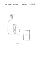
- FIG. 1 is a schematic representation of a high pressure paint spray system incorporating the fluid pressure switch of the present invention
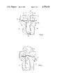
- FIG. 2 is an enlarged cross-sectional view of the fluid pressure switch of the present invention
- FIG. 3 is an enlarged detail view of the fluid pressure switch of FIG. 2 showing the diaphragm and operating piston;
- FIG. 4 is a detail view similar to that of FIG. 3 showing the operating movement of the piston.
- FIG. 1 a hydraulic pressure operated switch, designated 10, which is arranged in fluid line 12 for the purpose of sensing the fluid pressure therein.
- Fluid line 12 supplies pressurized fluid from hydraulic pump 14 to a pressurized fluid distributor which, in this case, is a hydraulically operated spray gun, designated 16.
- Hydraulic pressure switch 10 is adapted to electrically control, via electrical wires 18 and 20, the operation of hydraulic pump 14. It is to be appreciated that switch 10 can be used to control the operation of other devices, such as valves, clutches, etc.
- liquid paint If liquid paint is to be atomized and sprayed by spray gun 16, it must be supplied to spray gun 16 through fluid line 12 at a pressure sufficient to cause atomization when exiting from the spray nozzle of spray gun 16.
- hydraulic pump 14 could be switched on for pressurizing the fluid at a low pressure of 1500 psi and turned off at the higher pressure of 2000 psi, thus resulting in a differential of 500 psi. This differential between 1500 and 2000 psi would be sufficient to result in atomization of the fluid at all pressures therebetween.
- hydraulic pump 14 when the fluid pressure has reached 2000 psi, hydraulic pump 14 would be turned off and, as spray gun 16 is operated, reducing the fluid pressure to 1500 psi, hydraulic pump 14 would be turned on to increase the fluid pressure to the upper limit. It is the purpose of hydraulic pressure switch 10 to activate the start and stop cycles of hydraulic pump 14.
- Hydraulic pressure switch 10 is also adjustable so as to regulate the pressure of the fluid delivered by hydraulic pump 14 to spray gun 16.
- pressure switch 10 can be adjusted so that the highest pressure delivered by hydraulic pump 14 to fluid line 12 is 900 psi, at which point the pump is turned off.
- the differential pressure at which the pump is again turned on so as to increase the fluid pressure in fluid line 12, in such a case, should not be the 500 psi differential of the higher operating pressure since, at a pressure of 400 psi, the fluid exiting from the nozzle of spray gun 16 may not atomize.
- the differential pressure is simultaneously changed automatically within pressure switch 10 so that a smaller differential is provided at the lower pressures.
- hydraulic pressure switch 10 comprises a housing, designated 22, a transducer assembly, designated 24, a switch cap, designated 26, and a pressure adjustment assembly, designated 28.
- Housing 22 houses transducer assembly 24 and adjustment assembly 28 and is firmly attached to switch cap assembly 26 by formed metal retainer 30.
- Transducer assembly 24 includes axially movable piston 32, microswitch 34 and bushing 36.
- Bushing 36 is provided with a central bore 38 which guides head 40 of piston 32 for axial movement therein.
- Microswitch 34 is secured to piston 32 and includes an activating push button 42 which is adapted to cooperate with stop 44 of housing 22 to activate microswitch 34 in response to the axial movement of piston 32.
- microswitch 34 Electrical control wires 18 and 20, which control the on and off cycles of hydraulic pump 14, are operatively connected to microswitch 34.
- the type of microswitch utilized herein is a normally closed switch having a 0.002 inch differential movement. Thus, 0.002 inch movement of push button 42 downwardly is required to open the switch and 0.002 inch movement upwardly therefrom is required to close the switch.
- Switch cap assembly 26 includes a switch cap 46 having a bore 48 therethrough which is aligned with bore 38 of bushing 36 and head 40 of piston 32. Fixedly disposed between switch cap 46 and bushing 36 and covering the crown of piston head 40 is a diaphragm, designated 50, which seals the operating mechanism of pressure switch 10 from the fluid whose pressure is to be sensed in bore 48. Diaphragm 50 also permits the differential pressure of the switch to vary as a function of the adjustable operating pressure thereof.
- Piston 32 is maintained in its normal position defined by the seating of shoulder 52 of the piston on face 53 of bushing 36 by the bias of compression spring 54 which acts axially against rod 56 of piston 32.
- the adjustment of the spring force of spring 54 by compressing or releasing the length thereof changes the necessary force to lift piston 32 off its seat so as to move push button 42 and activate microswitch 34. This change in spring force changes or alters the hydraulic pressure necessary to operate switch 10. Adjustment of the force produced by spring 54 is accomplished by means of adjustment assembly 28 which includes an adjustment knob 58 threadably engaged at 59 with housing 22, a spring retainer 60 engaging the upper end of spring 54, and a spring retainer 62 engaging the lower end of spring 54.
- Spring retainer 60 is operatively engaged with adjustment knob 58 and spring retainer 62 is engaged with rod 56 of piston 32.
- Maximum setting for the switch can be provided by means of set screw 64 which is threadably engaged with adjustment knob 58 and which engages upper spring retainer 60.
- set screw 64 which is threadably engaged with adjustment knob 58 and which engages upper spring retainer 60.
- FIG. 3 a detail of pressure switch 10 is shown wherein it can be seen that diaphragm 50 is pinioned at its outer circumferential rim 70 between the mating surfaces of bushing 36 and switch cap 46.
- Switch cap assembly 26 includes an O-ring seal, designated 72, which engages diaphragm 50 radially inwardly from rim 70 to seal against the pressurized fluid in bore 48 and prevent it from passing between the engaging surfaces of bushing 36 and switch cap 46.
- An annular segment of diaphragm 50, designated 71, between pinioned circumferential rim 70 and bore 38 of bushing 36 remains unrestrained by reason of the annular undercut 73 in the face of switch cap 46.
- Diaphragm 50 must be such as to stretch sufficiently in conjunction with the movement of piston 32 against which it abuts to activate microswitch 34 without exceeding the elastic limit or result in tearing of the material of the diaphragm. Any suitable material may be used for diaphragm 50 as long as the spring rate of the material when stretched is satisfactory (as discussed below).
- diaphragm 50 is comprised of two layers superimposed one on the other, a first layer, designated 74, consists of a layer of relatively soft polyethylene whereas the second layer, designated 76, adjacent the crown of piston head 40 consists of a thin layer of stiff material such as nylon.
- Nylon layer 76 because of its stiffness, cannot be extruded between piston head 40 and bore 38 as a result of the high pressure of the fluid in bore 48. If a softer material were utilized for layer 76, such as polyethylene, the material would be extruded between the piston and bore 38 and cause the piston to jam. Also, polyethylene layer 74 helps to evenly distribute the hydraulic pressure over layer 76.
- diaphragm 50 is caused to stretch radially in a circular segment between a point 77, radially inwardly from its pinioned rim 70, and a point 78 radially inwardly from bore 38 of bushing 36.
- the length of the distance between points 77 and 78 determines the spring rate of diaphragm 50.
- This spring rate results in a spring force which acts against the fluid pressure in bore 48 and the more diaphragm 50 is stretched, the greater is the spring force produced.
- the amount of this spring force produced when piston 32 moves sufficiently to overcome the differential movement of microswitch 34 determines the pressure differential of switch 10.
- the differential pressure is determined by the amount of force, over and above that required to overcome spring 54, which equals the force developed by the stretching of diaphragm 50 between points 77 and 78 due to the distance moved of piston 32 whereat push button 42 of microswitch 34 is activated. Points 77 and 78 defining the circular segment in which stretching or extension of diaphragm 50 occurs is dependent upon the amount of hydraulic pressure exerted on diaphragm 50 by the fluid in bore 48.
- hydraulic pump 14 functions and pressurizes the fluid in fluid line 12 which communicates with bore 48 of switch cap assembly 26 of switch 10.
- the hydraulic pressure in bore 48 is sensed by diaphragm 50 therein which, in turn, transmits this pressure to the crown of piston head 40 of piston 32.
- diaphragm 50 begins to stretch between some point radially inwardly of its pinioned outer rim 70 and point 78 thereon.
- the amount of hydraulic pressure exerted by the fluid in bore 48 determines the extent of the circular or annular segment of diaphragm 50 which will stretch.
- the amount of stretch of this circular segment of diaphragm 50 which results from the axial movement of piston 32 sufficient to activate push button 42 of microswitch 34, is translated into a force which determines the pressure differential for the switch operation at that pressure setting. Therefore, when the hydraulic pressure is at the low end of the differential, piston 32 will have moved sufficiently to overcome the differential movement of microswitch 34 and signal the start mode of hydraulic pump 14. When the hydraulic pressure of the fluid has reached the upper end of the differential, piston 32 will have moved the distance sufficient to overcome the differential movement of microswitch 34 and thus open the switch and signal the stop mode of pump 14.
Landscapes
- Physics & Mathematics (AREA)
- Fluid Mechanics (AREA)
- Switches Operated By Changes In Physical Conditions (AREA)
Abstract
Description
Claims (10)
Priority Applications (1)
| Application Number | Priority Date | Filing Date | Title |
|---|---|---|---|
| US07/052,269 US4755638A (en) | 1987-05-21 | 1987-05-21 | Pressure operated switch for controlling an airless paint pump |
Applications Claiming Priority (1)
| Application Number | Priority Date | Filing Date | Title |
|---|---|---|---|
| US07/052,269 US4755638A (en) | 1987-05-21 | 1987-05-21 | Pressure operated switch for controlling an airless paint pump |
Publications (1)
| Publication Number | Publication Date |
|---|---|
| US4755638A true US4755638A (en) | 1988-07-05 |
Family
ID=21976498
Family Applications (1)
| Application Number | Title | Priority Date | Filing Date |
|---|---|---|---|
| US07/052,269 Expired - Fee Related US4755638A (en) | 1987-05-21 | 1987-05-21 | Pressure operated switch for controlling an airless paint pump |
Country Status (1)
| Country | Link |
|---|---|
| US (1) | US4755638A (en) |
Cited By (15)
| Publication number | Priority date | Publication date | Assignee | Title |
|---|---|---|---|---|
| US5074467A (en) * | 1990-11-30 | 1991-12-24 | Geberth John Daniel | High volume low pressure spray painting system, method of operation and control system therefor |
| US5198631A (en) * | 1991-09-11 | 1993-03-30 | General Electric Company | Pressure responsive control device |
| US5965822A (en) * | 1998-04-22 | 1999-10-12 | Wu; Min | Calibration feature for a pressure gauge |
| USH1832H (en) * | 1996-06-03 | 2000-02-01 | The United States Of America As Represented By The Secretary Of The Army | Electromagnetically transparent fluidic operators for remote operation of electric switches and method of adapting electric switches for remote, fluidic operation |
| EP1037223A2 (en) * | 1999-03-10 | 2000-09-20 | Alan D. Jorczak | Controller switch assembly |
| US6419456B1 (en) * | 1999-10-22 | 2002-07-16 | Wagner Spray Tech Corporation | Switch for controlling the motor of a piston pump |
| US20030094211A1 (en) * | 2001-11-21 | 2003-05-22 | Niederquell Bradley O. | Apparatus and method for filling a painting robot canister |
| US6599107B2 (en) | 1999-10-22 | 2003-07-29 | Wagner Spray Tech Corporation | Piston pump having housing with a pump housing and a pump assembly drive housing formed therein |
| FR2886068A1 (en) * | 2005-05-23 | 2006-11-24 | Somfy Sas | Electrical actuator control box for winding automatism of e.g. blind, has displacement mechanism displacing printed circuit in box between active position, in which switch is switched, and rest position, in which switch is not switched |
| US7437919B1 (en) | 2007-04-18 | 2008-10-21 | Min Wu | Multiple-function tire valve cap with low pressure safety indicator |
| US20090317262A1 (en) * | 2006-07-17 | 2009-12-24 | Briggs & Stratton Corporation | Engine speed control for pressure washer |
| US20100282862A1 (en) * | 2009-05-06 | 2010-11-11 | Briggs & Stratton Corporation | Pressure washer with throttle control |
| US20110006133A1 (en) * | 2009-07-10 | 2011-01-13 | Lemmer Spray Systems Ltd. | Pressure differential motor control system and method |
| US20110142685A1 (en) * | 2009-12-16 | 2011-06-16 | Briggs & Strantton Corporation | Pump unloader valve and engine throttle system |
| WO2020200713A1 (en) * | 2019-03-29 | 2020-10-08 | Condor-Werke Gebr. Frede GmbH | Pressure switch device |
Citations (7)
| Publication number | Priority date | Publication date | Assignee | Title |
|---|---|---|---|---|
| US2808484A (en) * | 1952-05-21 | 1957-10-01 | Manning Maxwell & Moore Inc | Pressure operated switch |
| FR1494122A (en) * | 1966-05-09 | 1967-09-08 | Improvement in pressure switches | |
| US3516279A (en) * | 1967-02-23 | 1970-06-23 | Alphamatic Corp | Method for adjusting a pressure operated switch utilizing the nonlinear properties of a biasing means |
| US3848517A (en) * | 1972-08-28 | 1974-11-19 | Nason Co | Pressure sensitive device for operating a switch or the like |
| US4184809A (en) * | 1977-05-11 | 1980-01-22 | Louis Beck | Diaphragm pump construction having pulsator piston and mechanically actuated means to supply pulsator fluid |
| US4317971A (en) * | 1980-05-27 | 1982-03-02 | Rk Industries | Adjustable pressure and vacuum limit switch valve |
| US4438305A (en) * | 1981-10-13 | 1984-03-20 | Sor, Inc. | Fire resistant pressure switch |
-
1987
- 1987-05-21 US US07/052,269 patent/US4755638A/en not_active Expired - Fee Related
Patent Citations (7)
| Publication number | Priority date | Publication date | Assignee | Title |
|---|---|---|---|---|
| US2808484A (en) * | 1952-05-21 | 1957-10-01 | Manning Maxwell & Moore Inc | Pressure operated switch |
| FR1494122A (en) * | 1966-05-09 | 1967-09-08 | Improvement in pressure switches | |
| US3516279A (en) * | 1967-02-23 | 1970-06-23 | Alphamatic Corp | Method for adjusting a pressure operated switch utilizing the nonlinear properties of a biasing means |
| US3848517A (en) * | 1972-08-28 | 1974-11-19 | Nason Co | Pressure sensitive device for operating a switch or the like |
| US4184809A (en) * | 1977-05-11 | 1980-01-22 | Louis Beck | Diaphragm pump construction having pulsator piston and mechanically actuated means to supply pulsator fluid |
| US4317971A (en) * | 1980-05-27 | 1982-03-02 | Rk Industries | Adjustable pressure and vacuum limit switch valve |
| US4438305A (en) * | 1981-10-13 | 1984-03-20 | Sor, Inc. | Fire resistant pressure switch |
Cited By (26)
| Publication number | Priority date | Publication date | Assignee | Title |
|---|---|---|---|---|
| US5074467A (en) * | 1990-11-30 | 1991-12-24 | Geberth John Daniel | High volume low pressure spray painting system, method of operation and control system therefor |
| US5198631A (en) * | 1991-09-11 | 1993-03-30 | General Electric Company | Pressure responsive control device |
| US5300741A (en) * | 1991-09-11 | 1994-04-05 | General Electric Company | Pressure responsive control device |
| US5524333A (en) * | 1991-09-11 | 1996-06-11 | General Electric Company | Method of assembling a pressure responsive control device |
| USH1832H (en) * | 1996-06-03 | 2000-02-01 | The United States Of America As Represented By The Secretary Of The Army | Electromagnetically transparent fluidic operators for remote operation of electric switches and method of adapting electric switches for remote, fluidic operation |
| US5965822A (en) * | 1998-04-22 | 1999-10-12 | Wu; Min | Calibration feature for a pressure gauge |
| US20030221941A1 (en) * | 1999-03-10 | 2003-12-04 | Jorczak Alan D. | Controller switch assembly |
| EP1037223A3 (en) * | 1999-03-10 | 2002-01-02 | Alan D. Jorczak | Controller switch assembly |
| US6486418B1 (en) | 1999-03-10 | 2002-11-26 | Entech Controls Corporation | Controller switch assembly |
| EP1037223A2 (en) * | 1999-03-10 | 2000-09-20 | Alan D. Jorczak | Controller switch assembly |
| US6787717B2 (en) | 1999-03-10 | 2004-09-07 | Entech Controls Corporation | Controller switch assembly |
| US6419456B1 (en) * | 1999-10-22 | 2002-07-16 | Wagner Spray Tech Corporation | Switch for controlling the motor of a piston pump |
| US6599107B2 (en) | 1999-10-22 | 2003-07-29 | Wagner Spray Tech Corporation | Piston pump having housing with a pump housing and a pump assembly drive housing formed therein |
| US20030094211A1 (en) * | 2001-11-21 | 2003-05-22 | Niederquell Bradley O. | Apparatus and method for filling a painting robot canister |
| US6705361B2 (en) * | 2001-11-21 | 2004-03-16 | Fanuc Robotics North America, Inc. | Apparatus and method for filling a painting robot canister |
| FR2886068A1 (en) * | 2005-05-23 | 2006-11-24 | Somfy Sas | Electrical actuator control box for winding automatism of e.g. blind, has displacement mechanism displacing printed circuit in box between active position, in which switch is switched, and rest position, in which switch is not switched |
| EP1727169A2 (en) * | 2005-05-23 | 2006-11-29 | Somfy SAS | Operable housing for an electrical actuator, and corresponding mechanism |
| EP1727169A3 (en) * | 2005-05-23 | 2009-06-24 | Somfy SAS | Operable housing for an electrical actuator, and corresponding mechanism |
| US20090317262A1 (en) * | 2006-07-17 | 2009-12-24 | Briggs & Stratton Corporation | Engine speed control for pressure washer |
| US7437919B1 (en) | 2007-04-18 | 2008-10-21 | Min Wu | Multiple-function tire valve cap with low pressure safety indicator |
| US20080257027A1 (en) * | 2007-04-18 | 2008-10-23 | Min Wu | Multiple-function tire valve cap with low pressure safety indicator |
| US20100282862A1 (en) * | 2009-05-06 | 2010-11-11 | Briggs & Stratton Corporation | Pressure washer with throttle control |
| US20110006133A1 (en) * | 2009-07-10 | 2011-01-13 | Lemmer Spray Systems Ltd. | Pressure differential motor control system and method |
| US8197221B2 (en) | 2009-07-10 | 2012-06-12 | Thomas Lemmer | Pressure differential motor control system and method |
| US20110142685A1 (en) * | 2009-12-16 | 2011-06-16 | Briggs & Strantton Corporation | Pump unloader valve and engine throttle system |
| WO2020200713A1 (en) * | 2019-03-29 | 2020-10-08 | Condor-Werke Gebr. Frede GmbH | Pressure switch device |
Similar Documents
| Publication | Publication Date | Title |
|---|---|---|
| US4755638A (en) | Pressure operated switch for controlling an airless paint pump | |
| US6729849B2 (en) | Constant pressure pump controller system | |
| US4238073A (en) | Paint spray apparatus having pressure actuated control | |
| US3622078A (en) | Spraying device for pastelike material with shutoff valve means for the material | |
| US5265644A (en) | Fuel pressure regulator | |
| US4971527A (en) | Regulator valve for an ink marking system | |
| US5284299A (en) | Pressure compensated HVLP spray gun | |
| CA1054061A (en) | Digital flow pressure regulator | |
| US5799879A (en) | Device for producing a fluid jet | |
| US5622204A (en) | Flow control valve having flow adjustable by variable ring | |
| US3514017A (en) | Pressure regulating structure for piston pump | |
| JPH0555886B2 (en) | ||
| US4966183A (en) | Pressure regulator | |
| US4754923A (en) | Spray gun with automatic valve opening control means | |
| US4896799A (en) | Device with button incorporating a shut-off means, for delivering liquids in atomized form | |
| US5035357A (en) | Pressure control valve and system | |
| US3099282A (en) | Pressure operated valve means for controlling flow in a flow line | |
| US6371733B1 (en) | Pump with hydraulic load sensor and controller | |
| CA2128960A1 (en) | Spray element especially for mold sprayers | |
| US3954354A (en) | Sliding piston pump, especially for vapourizers | |
| US3374803A (en) | Volume and flow control device | |
| US5788128A (en) | High viscosity low pressure non-contact glue-dispenser | |
| JP2649181B2 (en) | Automatic control device for variable displacement pump | |
| US6382243B2 (en) | Pressure-reducing valve | |
| US4982899A (en) | Device for regulating discharge volumes of a nozzle |
Legal Events
| Date | Code | Title | Description |
|---|---|---|---|
| AS | Assignment |
Owner name: TITAN TOOL, INC., F/K/A TITAN PROFESSIONAL TOOL, I Free format text: ASSIGNMENT OF ASSIGNORS INTEREST.;ASSIGNOR:GEBERTH, JOHN D., JR.;REEL/FRAME:005725/0301 Effective date: 19910605 |
|
| AS | Assignment |
Owner name: CONTINENTAL BANK N.A. Free format text: SECURITY INTEREST;ASSIGNOR:TITAN PROFESSIONAL TOOL, INC;REEL/FRAME:005736/0308 Effective date: 19910605 |
|
| REMI | Maintenance fee reminder mailed | ||
| FPAY | Fee payment |
Year of fee payment: 4 |
|
| SULP | Surcharge for late payment | ||
| AS | Assignment |
Owner name: TITAN TOOL, INC., NEW JERSEY Free format text: ASSIGNMENT OF ASSIGNORS INTEREST;ASSIGNOR:GEBERTH, JOHN D., JR.;REEL/FRAME:006545/0285 Effective date: 19930521 |
|
| AS | Assignment |
Owner name: TITAN TOOL, INC., NEW JERSEY Free format text: RELEASE;ASSIGNOR:CONTINENTAL BANK;REEL/FRAME:007132/0588 Effective date: 19940831 |
|
| AS | Assignment |
Owner name: HELLER FINANCIAL, INC., ILLINOIS Free format text: CONTINUING SECURITY INTEREST AND CONDITIONAL ASSIGNMENT;ASSIGNOR:TITAN TOOL, INC.;REEL/FRAME:007133/0966 Effective date: 19940831 |
|
| FEPP | Fee payment procedure |
Free format text: PAT HLDR NO LONGER CLAIMS SMALL ENT STAT AS INDIV INVENTOR (ORIGINAL EVENT CODE: LSM1); ENTITY STATUS OF PATENT OWNER: LARGE ENTITY Free format text: PAYOR NUMBER ASSIGNED (ORIGINAL EVENT CODE: ASPN); ENTITY STATUS OF PATENT OWNER: LARGE ENTITY |
|
| AS | Assignment |
Owner name: HELLER FINANCIAL, INC., ILLINOIS Free format text: ASSIGNMENT OF ASSIGNORS INTEREST;ASSIGNOR:TITAN TOOL, INC.;REEL/FRAME:007833/0061 Effective date: 19950804 |
|
| FPAY | Fee payment |
Year of fee payment: 8 |
|
| AS | Assignment |
Owner name: TITAN TOOL, INC., NEW JERSEY Free format text: RELEASE BY SECURED PARTY;ASSIGNOR:HELLER FINANCIAL INC.;REEL/FRAME:009893/0915 Effective date: 19990125 |
|
| AS | Assignment |
Owner name: WAGNER TITAN INC., MINNESOTA Free format text: ASSIGNMENT OF ASSIGNORS INTEREST;ASSIGNOR:TITAN TOOL, INC.;REEL/FRAME:009883/0745 Effective date: 19990125 |
|
| AS | Assignment |
Owner name: U.S. BANK NATIONAL ASSOCIATION, MINNESOTA Free format text: SECURITY AGREEMENT;ASSIGNOR:TITAN TOOL, INC.;REEL/FRAME:010121/0118 Effective date: 19990430 |
|
| REMI | Maintenance fee reminder mailed | ||
| LAPS | Lapse for failure to pay maintenance fees | ||
| FP | Lapsed due to failure to pay maintenance fee |
Effective date: 20000705 |
|
| STCH | Information on status: patent discontinuation |
Free format text: PATENT EXPIRED DUE TO NONPAYMENT OF MAINTENANCE FEES UNDER 37 CFR 1.362 |