US4755153A - Capacitor cover for CG type capacitor - Google Patents
Capacitor cover for CG type capacitor Download PDFInfo
- Publication number
- US4755153A US4755153A US07/033,872 US3387287A US4755153A US 4755153 A US4755153 A US 4755153A US 3387287 A US3387287 A US 3387287A US 4755153 A US4755153 A US 4755153A
- Authority
- US
- United States
- Prior art keywords
- tenon
- disc
- insert
- aperture
- capacitor
- Prior art date
- Legal status (The legal status is an assumption and is not a legal conclusion. Google has not performed a legal analysis and makes no representation as to the accuracy of the status listed.)
- Expired - Fee Related
Links
- 239000003990 capacitor Substances 0.000 title claims abstract description 22
- 238000000034 method Methods 0.000 claims description 12
- 239000000463 material Substances 0.000 claims description 8
- 239000004033 plastic Substances 0.000 description 7
- 239000002184 metal Substances 0.000 description 4
- 239000004677 Nylon Substances 0.000 description 1
- 238000010276 construction Methods 0.000 description 1
- 239000000615 nonconductor Substances 0.000 description 1
- 229920001778 nylon Polymers 0.000 description 1
- 229920001296 polysiloxane Polymers 0.000 description 1
Images

Classifications
-
- H—ELECTRICITY
- H01—ELECTRIC ELEMENTS
- H01G—CAPACITORS; CAPACITORS, RECTIFIERS, DETECTORS, SWITCHING DEVICES, LIGHT-SENSITIVE OR TEMPERATURE-SENSITIVE DEVICES OF THE ELECTROLYTIC TYPE
- H01G4/00—Fixed capacitors; Processes of their manufacture
- H01G4/002—Details
- H01G4/228—Terminals
- H01G4/236—Terminals leading through the housing, i.e. lead-through
Definitions
- Electrolytic capacitors commonly use plastic discs as the end closures or covers for the capacitor. Such material serves as a good electrical insulator for the electrical leads running from the capacitor. Electrical contact between an internal lead of the capacitor and an outside terminal is normally made through a rivet connection, the rivet extending through an aperture in the closing. This arrangemenrt causes difficulty in securing a tight, secure fit between the rivet and the plastic closure. Such difficulty causes the electrical path between the terminal and the electrical leads to be broken down, thereby increasing the electrical resistance of the system.
- the present invention is concerned with the provision of a novel means to secure an electrical-mechanical connection for electrical leads to a plastic capacitor end closure or cover and has as one of its objects the provision of such a connecting means that has a more reliable connection.
- Another object of the invention is to provide a good electrical connection between an electrical terminal and an internal lead of an electrolytic capacitor having a plastic end closure or cover.
- a further object of the invention is to provide a method of providing such an electrical connection that is simple, effective, and relatively inexpensive.
- a cover and terminal connection for a capacitor which comprises a disc fabricated of an electrically insulative material, at least one aperture in the disc, a metal insert extending through the aperture and having a knurled face adapted to engage the aperture to thereby provide an antitwist characteristic between the disc and the insert, a flange extending from and around the metal insert engaging the disc at the aperture to provide a washer and a seal with the disc, receiving means within the insert adapted to receive an electrical terminal, and retaining means holding an internal electrical lead into electrical contact with the metal insert.
- FIG. 1 is an exploded view of a terminal connection means for a capacitor showing the features of the invention.
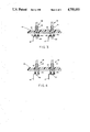
- FIG. 2 is a view taken along the line 2--2 of FIG. 1.
- FIGS. 3 and 4 are views taken along the lines 2--2 of FIG. 1 with internal capacitor leads in place.
- a typical prior art electrolytic capacitor employs an end closure or cover comprising a relatively flat disc 10 fabricated of an electrically insulative material such as plastic to seal the capacitor body.
- a pair of apertures 12 and 13 are provided in the disc through which suitable electrical terminals can be connected to internal electrical leads of the capacitor.
- it is very difficult to achieve a good mechanical connection between the capacitor's internal electrical leads 16 and 17 (FIGS. 3 and 4) and electrical terminals 18 and 19 due to the inability to achieve a snug fit between the electrical terminals and the apertures 12 and 13 of the plastic disc 10.
- Such a fit is needed in order to insure that the electrical path from the internal lead 16 and 17 to the terminals 18 and 19 will be unbroken.
- inserts 14 and 15 provide an antitwisting characteristic between the disc and the insert. More specifically, inserts 14 and 15 include an outer face having knurled portions 21 and 23 which are adapted to mate the walls of the apertures 12 and 13. The inserts also include tenons 18 and 19 which include shoulders 22 and 24. The shoulders provide tenons 26 and 28 of one diameter and tenons 30 and 32 of a smaller diameter.
- Silicone bushings 40 and 42 extend into apertures 12 and 13 to provide a good seal for inserts 14 and 15.
- Other suitable materials for the bushing would be an electrically insulative material such as a thermal plastic or a thermal set material such as nylon.
- FIGS. 2-4 the method of assembling the terminal connection into the cover can be described.
- inserts 14 and 15 have been forced into apertures 12 and 13 as well as bushings 40 and 42.
- large diameter tenons 26 and 28 have been deformed and flattened against disc 10 through shoulders 22 and 24 to provide washers 44 and 46 that are integral with the inserts 14 and 15 and which provide a seal between the inserts and disc 10.
- the tenons could be flattened through a commonly known orbital riveting process, for example.
- FIGS. 3 and 4 internal leads 16 and 17 have been positioned on washers 44 and 46 around smaller diameter tenons 30 and 32. The smaller diameter tenons are then deformed through orbital riveting to provide rivets 48 and 50 which hold the internal leads in place.
- Electrical terminals 18 and 19 can then be threaded into inserts 14 and 15.
Landscapes
- Engineering & Computer Science (AREA)
- Power Engineering (AREA)
- Manufacturing & Machinery (AREA)
- Microelectronics & Electronic Packaging (AREA)
- Connector Housings Or Holding Contact Members (AREA)
Abstract
Description
Claims (7)
Priority Applications (1)
| Application Number | Priority Date | Filing Date | Title |
|---|---|---|---|
| US07/033,872 US4755153A (en) | 1986-05-29 | 1987-04-02 | Capacitor cover for CG type capacitor |
Applications Claiming Priority (2)
| Application Number | Priority Date | Filing Date | Title |
|---|---|---|---|
| US86794686A | 1986-05-29 | 1986-05-29 | |
| US07/033,872 US4755153A (en) | 1986-05-29 | 1987-04-02 | Capacitor cover for CG type capacitor |
Related Parent Applications (1)
| Application Number | Title | Priority Date | Filing Date |
|---|---|---|---|
| US86794686A Continuation | 1986-05-29 | 1986-05-29 |
Publications (1)
| Publication Number | Publication Date |
|---|---|
| US4755153A true US4755153A (en) | 1988-07-05 |
Family
ID=26710247
Family Applications (1)
| Application Number | Title | Priority Date | Filing Date |
|---|---|---|---|
| US07/033,872 Expired - Fee Related US4755153A (en) | 1986-05-29 | 1987-04-02 | Capacitor cover for CG type capacitor |
Country Status (1)
| Country | Link |
|---|---|
| US (1) | US4755153A (en) |
Cited By (3)
| Publication number | Priority date | Publication date | Assignee | Title |
|---|---|---|---|---|
| US5288244A (en) * | 1993-04-19 | 1994-02-22 | Maxconn Incorporated | Connector assembly having fixed unitary fasteners for mounting to a panel |
| US5555485A (en) * | 1993-07-19 | 1996-09-10 | Philips Electronics North America Corporation | Device and method for insulating a dry film capacitor |
| EP0731476A1 (en) * | 1995-03-06 | 1996-09-11 | SIEMENS MATSUSHITA COMPONENTS GmbH & CO. KG | Electrical capacitor |
Citations (7)
| Publication number | Priority date | Publication date | Assignee | Title |
|---|---|---|---|---|
| US1902236A (en) * | 1930-11-24 | 1933-03-21 | Heintz & Kaufman Ltd | Connecting plug receptacle |
| US2443545A (en) * | 1944-12-11 | 1948-06-15 | Essex Wire Corp | Lead-in construction for electrical devices |
| GB956696A (en) * | 1961-12-08 | 1964-04-29 | Rendar Instr Ltd | Improvements in or relating to electrical terminal connectors |
| US3562700A (en) * | 1969-09-29 | 1971-02-09 | Cutler Hammer Inc | Electrical contact-terminal assembly |
| DE2403131A1 (en) * | 1974-01-23 | 1975-07-31 | Rau Swf Autozubehoer | Contact piece for panel of vehicle switching system - consists of round pin with stepped diameters in region of contact pushed through panel |
| US4047790A (en) * | 1976-01-07 | 1977-09-13 | General Electric Company | Insulative header assembly with feed through terminals |
| US4631631A (en) * | 1985-10-03 | 1986-12-23 | Emhart Industries, Inc. | Capacitor cover and terminal connection |
-
1987
- 1987-04-02 US US07/033,872 patent/US4755153A/en not_active Expired - Fee Related
Patent Citations (7)
| Publication number | Priority date | Publication date | Assignee | Title |
|---|---|---|---|---|
| US1902236A (en) * | 1930-11-24 | 1933-03-21 | Heintz & Kaufman Ltd | Connecting plug receptacle |
| US2443545A (en) * | 1944-12-11 | 1948-06-15 | Essex Wire Corp | Lead-in construction for electrical devices |
| GB956696A (en) * | 1961-12-08 | 1964-04-29 | Rendar Instr Ltd | Improvements in or relating to electrical terminal connectors |
| US3562700A (en) * | 1969-09-29 | 1971-02-09 | Cutler Hammer Inc | Electrical contact-terminal assembly |
| DE2403131A1 (en) * | 1974-01-23 | 1975-07-31 | Rau Swf Autozubehoer | Contact piece for panel of vehicle switching system - consists of round pin with stepped diameters in region of contact pushed through panel |
| US4047790A (en) * | 1976-01-07 | 1977-09-13 | General Electric Company | Insulative header assembly with feed through terminals |
| US4631631A (en) * | 1985-10-03 | 1986-12-23 | Emhart Industries, Inc. | Capacitor cover and terminal connection |
Cited By (3)
| Publication number | Priority date | Publication date | Assignee | Title |
|---|---|---|---|---|
| US5288244A (en) * | 1993-04-19 | 1994-02-22 | Maxconn Incorporated | Connector assembly having fixed unitary fasteners for mounting to a panel |
| US5555485A (en) * | 1993-07-19 | 1996-09-10 | Philips Electronics North America Corporation | Device and method for insulating a dry film capacitor |
| EP0731476A1 (en) * | 1995-03-06 | 1996-09-11 | SIEMENS MATSUSHITA COMPONENTS GmbH & CO. KG | Electrical capacitor |
Similar Documents
| Publication | Publication Date | Title |
|---|---|---|
| US4631631A (en) | Capacitor cover and terminal connection | |
| US6030723A (en) | Lead bushing and lead storage battery with lead bushing | |
| US5156032A (en) | Key assembly for vehicle anti-theft security system | |
| JPH05205804A (en) | Female-type terminal metal | |
| US4186984A (en) | Strain relief cover for a barrel terminal | |
| GB1529398A (en) | Connecting devices | |
| US4932897A (en) | Connector for an electrical signal transmitting cable | |
| US5558545A (en) | Battery terminal connector having pad contacts | |
| US4446332A (en) | Wire connector | |
| US4978314A (en) | Waterproof press-connecting connector | |
| US4755153A (en) | Capacitor cover for CG type capacitor | |
| US4950838A (en) | Electrical connector | |
| US5378162A (en) | Electrical plug bridge for an appliance plug | |
| US3091656A (en) | Terminal assembly | |
| US4304455A (en) | Waterproof electrical connector including improved cord grip | |
| US4295004A (en) | Wire connector | |
| US5722837A (en) | Coaxial cable connector | |
| US3439232A (en) | Capacitor terminal connection | |
| US5833499A (en) | Insulated battery-cable connector | |
| US6137053A (en) | Electric double-layer capacitor housing | |
| GB2177553A (en) | Capacitor terminal connection | |
| US5456609A (en) | Plug cap device for internal combustion engine | |
| JPH04111158U (en) | outlet | |
| US2887670A (en) | Wire termination device | |
| JPH06283228A (en) | Connector-integrated type waterproof case |
Legal Events
| Date | Code | Title | Description |
|---|---|---|---|
| AS | Assignment |
Owner name: EMHART INDUSTRIES, INC., FARMINGTON, CT. A CORP. O Free format text: ASSIGNMENT OF ASSIGNORS INTEREST.;ASSIGNORS:LIMANOWSKI, JOSEF K.;ARNOLD, THOMAS L.;HODGES, C. WAYNE;REEL/FRAME:004726/0066 Effective date: 19860519 |
|
| AS | Assignment |
Owner name: ELECTROLYTICS, INC., A CORP. OF DE Free format text: ASSIGNMENT OF ASSIGNORS INTEREST.;ASSIGNOR:EMHART INDUSTRIES, INC., A CORP. OF CT;REEL/FRAME:004760/0276 Effective date: 19870626 |
|
| REMI | Maintenance fee reminder mailed | ||
| LAPS | Lapse for failure to pay maintenance fees | ||
| FP | Lapsed due to failure to pay maintenance fee |
Effective date: 19920705 |
|
| STCH | Information on status: patent discontinuation |
Free format text: PATENT EXPIRED DUE TO NONPAYMENT OF MAINTENANCE FEES UNDER 37 CFR 1.362 |