US4733782A - Vending module having a selectable configuration and a wire hook adaptor - Google Patents
Vending module having a selectable configuration and a wire hook adaptor Download PDFInfo
- Publication number
- US4733782A US4733782A US06/938,642 US93864286A US4733782A US 4733782 A US4733782 A US 4733782A US 93864286 A US93864286 A US 93864286A US 4733782 A US4733782 A US 4733782A
- Authority
- US
- United States
- Prior art keywords
- back panel
- case
- adaptor
- hook
- wire
- Prior art date
- Legal status (The legal status is an assumption and is not a legal conclusion. Google has not performed a legal analysis and makes no representation as to the accuracy of the status listed.)
- Expired - Fee Related
Links
Images


Classifications
-
- A—HUMAN NECESSITIES
- A47—FURNITURE; DOMESTIC ARTICLES OR APPLIANCES; COFFEE MILLS; SPICE MILLS; SUCTION CLEANERS IN GENERAL
- A47F—SPECIAL FURNITURE, FITTINGS, OR ACCESSORIES FOR SHOPS, STOREHOUSES, BARS, RESTAURANTS OR THE LIKE; PAYING COUNTERS
- A47F5/00—Show stands, hangers, or shelves characterised by their constructional features
- A47F5/08—Show stands, hangers, or shelves characterised by their constructional features secured to the wall, ceiling, or the like; Wall-bracket display devices
- A47F5/0876—Display stands with fixed brackets or hooks for suspending articles
Definitions
- the present invention is directed to a vending case for storing therein small stackable retail items and, more particularly, to a flexible, cabinet-shaped module with hardware accessories which allow the retailer to configure the case to provide both variously sized storage bin and shelf space and/or a wire hook hanging area for supporting hangable items on wire hooks.
- Small stackable items such as cigarettes and the like are often displayed in and dispensed from relatively small open cases which contain horizontally extending shelves and vertical dividers to provide in the case variously sized and readily accessible bins for holding the stackable items therein.
- modular cases in kit form which the merchandiser can assemble to obtain the variously sized bin and shelf space.
- Optional attachments for the modular case include items such as a header for displaying information at the top of the case, a specially shaped bottom shelf, a so-called front face open shelf and other various accessories.
- FIGS. 1-4 The basic components of this known case are illustrated in FIGS. 1-4 and will be described in greater detail later herein.
- the case comes with a back panel which contains a plurality of specially shaped support holes arranged in a predetermined order.
- the accessories such as the vertical dividers etc., are formed with generally L-shaped hooks which are sized and spaced from each other to enable their insertion in the support holes to assure safe and secure attachment of the accessories to the back panel of the modular case.
- the bin and shelf space provided by this known device is quite useful for storing and displaying stackable items such as cigarettes and the like. It is not, however, optimized or useful for supporting the numerous small items which come with a hang hole in their packaging by which the items are intended to be hung on conventional and standardized wire hooks which are familiar to most shoppers.
- the wire hooks have an elongated, rather stiff, stem on which several of the packages may be hung and a prong arrangement which enables the wire hooks to be removably inserted into a vertically extending peg board.
- the peg board contains numerous and closely spaced prong receiving circular support holes.
- the support holes in the back panel of the modular cases for the stackable items are peculiarly shaped and specifically spaced to receive the special hooks disposed on the conventional accessories for the modular case.
- such cases have not been supplied with means for supporting wire hooks therein and the alternative of stacking the hangable items in such cases is impractical and unattractive.
- a modular case which includes a back panel containing a plurality of spaced mounting holes which are suitable for receiving and supporting various shelving accessories and which enable a user to create bin and shelf space in a desired configuration.
- the flexibility of the modular case is further enhanced with the inclusion of an adaptor having on one side thereof hook means which enable the adaptor to be secured to the back panel and in spaced relation to the hook means a front panel containing a plurality of holes which are suitable for receiving and supporting conventional wire hooks.
- the adaptor is formed of a single molded piece having a front plate with the plurality of wire hook receiving holes located thereon, a rear plate which is spaced from the front plate and connected thereto by several ribs or tabs which are spaced from one another and arranged so as not to interfere with the location of the wire hook holes, and several hooks on the rear plate which have the shape and spacing to fit and to be secured in mounting holes of the modular case.
- the modular case may include several adaptors which are vertically spaced from one another to create several rows of hanging space. It is also possible to populate the modular case with one or more of the foregoing adaptors in combination with the known shelving accessories to create any desired case configuration.
- the adaptor provides the ability to create in the same modular case both shelving and hanging space in any desired ratio and tailored to meet the specific needs of the user.
- FIG. 1A illustrates perspectively a basic prior art module for a retailing case and a vertical divider therefor.
- FIGS. 1B-1C illustrate the manner in which the hooks provided on the accessories for the module of FIG. 1A are secured to the module.
- FIG. 2 illustrates the module of FIG. 1A with additional horizontal shelves.
- FIG. 3 shows the case of FIG. 1A in its assembled form.
- FIGS. 4A-4C provide several sketches of conventional accessories that can be used in conjunction with the case of FIG. 1A.
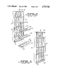
- FIG. 5 illustrates perspectively a novel wire hook adaptor in accordance with the present invention for the case of FIG. 1A.
- FIG. 6 is a cross-section of the adaptor of FIG. 5 along line 6--6.
- FIG. 7 illustrates the module of FIG. 1A which is provided with both several of the novel adaptors and other conventional accessories.
- FIGS. 1-4 illustrate a known retailing display case.
- Case 10 of FIG. 1 comprises a basic module 12 defining a generally rectangular space 14 located between a back panel 16, top wall 18, bottom wall 20 and side walls 20 and 22.
- the size of module 12 is not specially relevant but it is worth noting that one existing line of such cases is available in a width "w" measured between side walls 20, 22 of about 12 inches, a length "l “ which may be 24 or 29 inches and a depth "d" of about 4 inches.
- Back panel 16 contains a plurality of support holes 24 arranged both along horizontal lines 26 and vertical lines 28.
- Each support hole 24 has a main generally square opening 30 and a downwardly depending slot 32 whose function will become apparent later herein.
- Each one of a plurality of vertical dividers such as divider 34 is preferably comprised of a molded piece and includes a divider panel 36, extending perpendicularly to a relatively narrower base 38, and two or more hooks 40.
- any one of hooks 40 contains (FIGS. 1B, 1C) a top 42 which extends perpendicularly to back panel 16 , a downwardly depending lip 44 and a stiffening and positioning web 46 located centrally with respect to a lip 44 and top 42 as shown.
- the distal edge 48 of lip 44 is tapered to provide a larger clearance that facilities sliding of hook 40 down, over and behind back panel 16 thereby to secure the given accessory to the back panel.
- the spacing "s", in FIG. 1B, of lip 44 is about equal to the thickness of back panel 16.
- Hooks 44 enable the dividers and the various accessories to be secured to back panel 16 of case 10.
- the hooks 40 are aligned with and then inserted into the larger sized main openings 30 of mounting holes 24 provided in back panel 16. They are then pulled downwardly such that web 46 of hook 40 slides into slot 32 of mounting holes 24. Thereby, the dividers and accessories will become interlocked with and secured to back panel 16 of module 10.
- Main panel 36 of divider 34 is provided with several slots 50 which are inclined to the horizontal 52 and which further contain a notch 54.
- the slots 50 as will become apparent shortly, receive various shelves which are illustrated in FIG. 2.
- FIG. 1 further illustrates one of the accessory items for module 10 namely a so-called three wing feed shelf 56. It contains a base 58 and several dividers 60 and is preferably of molded construction. Hooks (not shown) of the type previously described are provided on the back surface (not shown) of a base 62 which is inclined to the major plane of base 58. Consequently, upon securing shelf 56 to back panel 16, the base 58 is inclined at a small acute angle and items stored on shelf 56 will not slide off.
- FIG. 2 illustrates several horizontal dividers or shelves 64 each of which is formed with slots 66 which, as indicated by dotted lines 68, allow shelves 64 to be supported by and to interlock with vertical dividers 34 to provide a plurality of bins 70 which may be seen in FIG. 3.
- FIG. 2 also illustrates a bottom shelf 72 which is similar to horizontal shelves 64 but which contains a large lip 74 which conceals and provides a finish over the bottom region of case 10.
- FIG. 4A portrays a carton load shelf set 80.
- FIG. 4B shows a so-called front face shelf set 82 which contains a base 84 and several triangular dividers 86, providing a shelf generally similar to feed shelf 56 of FIG. 1A.
- a header 88 secured along the top of case 10 provides an information display center as well as a finish over the top of the case as illustrated in FIG. 4C.
- header 88 is hingedly secured to case 10 by hinges (not shown) which enable header 88 to swing upwardly to provide access to the space directly thereunder.
- module 12 is configurable to provide both bin and shelf space. The case is not, however, suited for or capable of supporting conventional wire hooks.
- the present invention provides, as depicted in FIGS. 5-7, an adaptor 90 having a generally rectangular transverse cross-section (FIG. 6) and including a front plate 92 containing a line of circular holes 94, a rear plate 96 spaced from front plate 92 and connected thereto by spacer tabs 98, and hooks 100 which are identical to hooks 40 previously described in relation to FIG 1A.
- an adaptor 90 having a generally rectangular transverse cross-section (FIG. 6) and including a front plate 92 containing a line of circular holes 94, a rear plate 96 spaced from front plate 92 and connected thereto by spacer tabs 98, and hooks 100 which are identical to hooks 40 previously described in relation to FIG 1A.
- the spacing and size of circular holes 94 is specifically selected to enable adaptor 90 to receive and support a plurality of wire hooks 102.
- Each wire hook includes a rigid stem 104 on which to hang items 106 having hang hole 108.
- An upwardly bent end 110 of wire hook 102 prevents the items 106 from falling off.
- Prongs 112 of wire hook 102 are insertable into circular holes 94 to thereby removably lock the wire hook in adaptor 90.
- Wire hook 102 remains horizontal as it is anchored against front plate 92 by anchor 103 of wire hook 102.
- Adaptor 90 is itself removably securable in back panel 16 of case 10 as its hooks 100 have the shape and spacing of hooks 40 provided on the conventional accessories for case 10.
- FIG. 6 depicts prong 112 in position in the space 114 provided between front and rear plates 92 and 96 of adaptor 90. Note one of the spacer tabs 98 which is shown in FIG. 6 behind prong 112.
- Adaptor 90 may span the width of case 10 or any portion thereof. In any configuration, the adaptor provides another option in configuring case 10.
- FIG. 7 illustrates one exemplary combination of adaptors with other accessories. But clearly any combination of accessories with one or more adaptors is contemplated.
- the invention enables the user to design or reconfigure, at any time, a case style which is fully populated by adaptors and wire hooks or adaptors in combination with the previously described standard accessories for case 10.
Abstract
Description
Claims (18)
Priority Applications (1)
| Application Number | Priority Date | Filing Date | Title |
|---|---|---|---|
| US06/938,642 US4733782A (en) | 1986-12-05 | 1986-12-05 | Vending module having a selectable configuration and a wire hook adaptor |
Applications Claiming Priority (1)
| Application Number | Priority Date | Filing Date | Title |
|---|---|---|---|
| US06/938,642 US4733782A (en) | 1986-12-05 | 1986-12-05 | Vending module having a selectable configuration and a wire hook adaptor |
Publications (1)
| Publication Number | Publication Date |
|---|---|
| US4733782A true US4733782A (en) | 1988-03-29 |
Family
ID=25471726
Family Applications (1)
| Application Number | Title | Priority Date | Filing Date |
|---|---|---|---|
| US06/938,642 Expired - Fee Related US4733782A (en) | 1986-12-05 | 1986-12-05 | Vending module having a selectable configuration and a wire hook adaptor |
Country Status (1)
| Country | Link |
|---|---|
| US (1) | US4733782A (en) |
Cited By (20)
| Publication number | Priority date | Publication date | Assignee | Title |
|---|---|---|---|---|
| US5213220A (en) * | 1992-06-03 | 1993-05-25 | O'brien Industries, Inc. | Display rack and blank for forming same |
| US5351839A (en) * | 1992-09-28 | 1994-10-04 | Decision Point Marketing, Inc. | Vertically adjustable pusher point of purchase display |
| US5465851A (en) * | 1994-11-09 | 1995-11-14 | Arrow Art Finishers, Inc. | Suspension-type display stand |
| US5620104A (en) * | 1995-02-27 | 1997-04-15 | Maglione; Stephen T. | Collapsible peg display stand |
| US5746328A (en) * | 1996-08-23 | 1998-05-05 | Decision Point Marketing, Inc. | Pegboard-mountable adjustable merchandising rack |
| US5762207A (en) * | 1996-01-17 | 1998-06-09 | Maglione; Stephen Thomas | Collapsible peg type display stand |
| US6675978B2 (en) * | 2002-03-04 | 2004-01-13 | Thomas M. Shea | Three sided and extended merchandising display with insertion channels for product identification and advertisement |
| US6929133B1 (en) * | 2000-01-10 | 2005-08-16 | Mechtronics Corporation | Display system and methods |
| US20080000858A1 (en) * | 2006-06-30 | 2008-01-03 | Fenerty Bryan M | Modular display apparatus |
| US20120132775A1 (en) * | 2007-03-08 | 2012-05-31 | Panasonic Corporation | Device mounting base |
| US20150096951A1 (en) * | 2013-02-19 | 2015-04-09 | Target Brands, Inc. | Free-standing display fixture |
| TWI491808B (en) * | 2013-12-13 | 2015-07-11 | Inventec Corp | Hanging structure and rack using the same |
| US20160157636A1 (en) * | 2013-09-06 | 2016-06-09 | T.M. Shea Products, Inc. | Signage systems and merchandising display assemblies |
| US10316522B2 (en) | 2016-03-25 | 2019-06-11 | Carefree/Scott Fetzer Company | Residential awning canopy assembly |
| US20190183243A1 (en) * | 2017-12-14 | 2019-06-20 | Bruegmann Gmbh & Co. Kg | System including article support surface and dividers |
| US10568423B1 (en) | 2018-09-13 | 2020-02-25 | Target Brands, Inc. | Display unit with shelf |
| USD884397S1 (en) | 2018-11-07 | 2020-05-19 | Target Brands, Inc. | Display unit |
| US10947736B2 (en) | 2016-03-25 | 2021-03-16 | Carefree/Scott Fetzer Company | Residential awning canopy assembly |
| US11337531B2 (en) * | 2018-04-27 | 2022-05-24 | Colgate-Palmolive Company | Modular point-of-sale display |
| US20220248875A1 (en) * | 2021-02-05 | 2022-08-11 | Westrock Shared Services, Llc | Cellulosic display structures and associated cellulosic display systems |
Citations (5)
| Publication number | Priority date | Publication date | Assignee | Title |
|---|---|---|---|---|
| US3976201A (en) * | 1975-03-12 | 1976-08-24 | Pacific Electricord Company | Supporting and displaying apparatus for merchandise items |
| US4029282A (en) * | 1975-05-02 | 1977-06-14 | Metalworks Limited | Wall bracket and clip arrangement |
| US4606466A (en) * | 1984-04-02 | 1986-08-19 | Cannon Equipment Company | Pegbar display device having a carrier for graphic identification |
| US4610413A (en) * | 1983-07-15 | 1986-09-09 | Cannon Equipment Company | Pegbar display device |
| US4615503A (en) * | 1985-05-02 | 1986-10-07 | Clamp Swing Pricing Co. | Deli pegbar apparatus |
-
1986
- 1986-12-05 US US06/938,642 patent/US4733782A/en not_active Expired - Fee Related
Patent Citations (5)
| Publication number | Priority date | Publication date | Assignee | Title |
|---|---|---|---|---|
| US3976201A (en) * | 1975-03-12 | 1976-08-24 | Pacific Electricord Company | Supporting and displaying apparatus for merchandise items |
| US4029282A (en) * | 1975-05-02 | 1977-06-14 | Metalworks Limited | Wall bracket and clip arrangement |
| US4610413A (en) * | 1983-07-15 | 1986-09-09 | Cannon Equipment Company | Pegbar display device |
| US4606466A (en) * | 1984-04-02 | 1986-08-19 | Cannon Equipment Company | Pegbar display device having a carrier for graphic identification |
| US4615503A (en) * | 1985-05-02 | 1986-10-07 | Clamp Swing Pricing Co. | Deli pegbar apparatus |
Cited By (27)
| Publication number | Priority date | Publication date | Assignee | Title |
|---|---|---|---|---|
| US5213220A (en) * | 1992-06-03 | 1993-05-25 | O'brien Industries, Inc. | Display rack and blank for forming same |
| US5351839A (en) * | 1992-09-28 | 1994-10-04 | Decision Point Marketing, Inc. | Vertically adjustable pusher point of purchase display |
| US5465851A (en) * | 1994-11-09 | 1995-11-14 | Arrow Art Finishers, Inc. | Suspension-type display stand |
| US5620104A (en) * | 1995-02-27 | 1997-04-15 | Maglione; Stephen T. | Collapsible peg display stand |
| US5762207A (en) * | 1996-01-17 | 1998-06-09 | Maglione; Stephen Thomas | Collapsible peg type display stand |
| US5746328A (en) * | 1996-08-23 | 1998-05-05 | Decision Point Marketing, Inc. | Pegboard-mountable adjustable merchandising rack |
| US6929133B1 (en) * | 2000-01-10 | 2005-08-16 | Mechtronics Corporation | Display system and methods |
| US6675978B2 (en) * | 2002-03-04 | 2004-01-13 | Thomas M. Shea | Three sided and extended merchandising display with insertion channels for product identification and advertisement |
| US20080000858A1 (en) * | 2006-06-30 | 2008-01-03 | Fenerty Bryan M | Modular display apparatus |
| US20120132775A1 (en) * | 2007-03-08 | 2012-05-31 | Panasonic Corporation | Device mounting base |
| US9125503B2 (en) * | 2013-02-19 | 2015-09-08 | Target Brands, Inc. | Free-standing display fixture |
| US20150096951A1 (en) * | 2013-02-19 | 2015-04-09 | Target Brands, Inc. | Free-standing display fixture |
| US20150351560A1 (en) * | 2013-02-19 | 2015-12-10 | Target Brands, Inc. | Free-standing display fixture |
| US9439519B2 (en) * | 2013-02-19 | 2016-09-13 | Target Brands, Inc. | Free-standing display fixture |
| US20160157636A1 (en) * | 2013-09-06 | 2016-06-09 | T.M. Shea Products, Inc. | Signage systems and merchandising display assemblies |
| US9867483B2 (en) * | 2013-09-06 | 2018-01-16 | T.M. Shea Products, Inc. | Signage systems and merchandising display assemblies |
| TWI491808B (en) * | 2013-12-13 | 2015-07-11 | Inventec Corp | Hanging structure and rack using the same |
| US10947736B2 (en) | 2016-03-25 | 2021-03-16 | Carefree/Scott Fetzer Company | Residential awning canopy assembly |
| US10316522B2 (en) | 2016-03-25 | 2019-06-11 | Carefree/Scott Fetzer Company | Residential awning canopy assembly |
| US11459765B2 (en) | 2016-03-25 | 2022-10-04 | Carefree/Soott Fetzer Company | Residential awning canopy assembly |
| US20190183243A1 (en) * | 2017-12-14 | 2019-06-20 | Bruegmann Gmbh & Co. Kg | System including article support surface and dividers |
| US10617206B2 (en) * | 2017-12-14 | 2020-04-14 | Bruegmann Gmbh & Co. Kg | System including article support surface and dividers |
| US11337531B2 (en) * | 2018-04-27 | 2022-05-24 | Colgate-Palmolive Company | Modular point-of-sale display |
| US10568423B1 (en) | 2018-09-13 | 2020-02-25 | Target Brands, Inc. | Display unit with shelf |
| USD884397S1 (en) | 2018-11-07 | 2020-05-19 | Target Brands, Inc. | Display unit |
| US20220248875A1 (en) * | 2021-02-05 | 2022-08-11 | Westrock Shared Services, Llc | Cellulosic display structures and associated cellulosic display systems |
| US11839316B2 (en) * | 2021-02-05 | 2023-12-12 | Westrock Shared Services, Llc | Cellulosic display structures and associated cellulosic display systems |
Similar Documents
| Publication | Publication Date | Title |
|---|---|---|
| US4733782A (en) | Vending module having a selectable configuration and a wire hook adaptor | |
| US5894940A (en) | Vertical wall rack and variable shoe holder arrangement | |
| US5577623A (en) | Composite gravity feed shelf | |
| US4905847A (en) | Display shelf system | |
| US3200960A (en) | Display devices | |
| US5509541A (en) | Bracket construction | |
| US5490600A (en) | Cooler display rack with adjustable gravity feed shelves | |
| US7891617B2 (en) | Mounting bracket for slat walls | |
| US6612448B2 (en) | Display rack with slidable member | |
| US5464103A (en) | Display rack | |
| US6601808B1 (en) | Display hook assembly with adjustable positioning back plate | |
| US7438186B2 (en) | Modular product display system | |
| US6786340B2 (en) | Ambidextrous merchandise fixture and method of displaying merchandise therefrom | |
| US5913433A (en) | Display shelf for elongated products | |
| US20080156752A1 (en) | Merchandising System | |
| US5423436A (en) | Pilfer-proof product distribution system | |
| JPH04259407A (en) | Implement for displaying booklet | |
| CA1268145A (en) | Merchandise display and dispenser rack | |
| CA2641689A1 (en) | Stock wing merchandise display | |
| EP0999773B1 (en) | Display rack | |
| US20050173359A1 (en) | Store lead-in fixture for a product dump table | |
| EP1891876B1 (en) | Card product display system | |
| GB2366185A (en) | Channel member for support purposes | |
| US4611720A (en) | Display rack system for candles | |
| US4018341A (en) | Merchandise display device |
Legal Events
| Date | Code | Title | Description |
|---|---|---|---|
| AS | Assignment |
Owner name: TRANS-WORLD MANUFACTURING CORPORATION, 360 MURRAY Free format text: ASSIGNMENT OF ASSIGNORS INTEREST.;ASSIGNORS:SPEZIAL, RONALD J.;PRENDERGAST, WILLIAM;REEL/FRAME:004658/0288 Effective date: 19861201 Owner name: TRANS-WORLD MANUFACTURING CORPORATION, A CORP. OF Free format text: ASSIGNMENT OF ASSIGNORS INTEREST;ASSIGNORS:SPEZIAL, RONALD J.;PRENDERGAST, WILLIAM;REEL/FRAME:004658/0288 Effective date: 19861201 |
|
| AS | Assignment |
Owner name: TRANS WORLD MARKETING CORPORATION Free format text: CHANGE OF NAME;ASSIGNOR:TRANS-WORLD MANUFACTURING CORP.;REEL/FRAME:005136/0960 Effective date: 19870212 |
|
| FEPP | Fee payment procedure |
Free format text: PAYOR NUMBER ASSIGNED (ORIGINAL EVENT CODE: ASPN); ENTITY STATUS OF PATENT OWNER: SMALL ENTITY |
|
| FPAY | Fee payment |
Year of fee payment: 4 |
|
| REMI | Maintenance fee reminder mailed | ||
| LAPS | Lapse for failure to pay maintenance fees | ||
| FP | Lapsed due to failure to pay maintenance fee |
Effective date: 19960403 |
|
| STCH | Information on status: patent discontinuation |
Free format text: PATENT EXPIRED DUE TO NONPAYMENT OF MAINTENANCE FEES UNDER 37 CFR 1.362 |