US4727708A - Wrap-around packaging machine - Google Patents
Wrap-around packaging machine Download PDFInfo
- Publication number
- US4727708A US4727708A US06/915,456 US91545686A US4727708A US 4727708 A US4727708 A US 4727708A US 91545686 A US91545686 A US 91545686A US 4727708 A US4727708 A US 4727708A
- Authority
- US
- United States
- Prior art keywords
- articles
- article support
- support means
- blank
- cam
- Prior art date
- Legal status (The legal status is an assumption and is not a legal conclusion. Google has not performed a legal analysis and makes no representation as to the accuracy of the status listed.)
- Expired - Lifetime
Links
Images


Classifications
-
- B—PERFORMING OPERATIONS; TRANSPORTING
- B65—CONVEYING; PACKING; STORING; HANDLING THIN OR FILAMENTARY MATERIAL
- B65B—MACHINES, APPARATUS OR DEVICES FOR, OR METHODS OF, PACKAGING ARTICLES OR MATERIALS; UNPACKING
- B65B5/00—Packaging individual articles in containers or receptacles, e.g. bags, sacks, boxes, cartons, cans, jars
- B65B5/06—Packaging groups of articles, the groups being treated as single articles
-
- B—PERFORMING OPERATIONS; TRANSPORTING
- B65—CONVEYING; PACKING; STORING; HANDLING THIN OR FILAMENTARY MATERIAL
- B65B—MACHINES, APPARATUS OR DEVICES FOR, OR METHODS OF, PACKAGING ARTICLES OR MATERIALS; UNPACKING
- B65B5/00—Packaging individual articles in containers or receptacles, e.g. bags, sacks, boxes, cartons, cans, jars
- B65B5/02—Machines characterised by incorporation of means for making the containers or receptacles
- B65B5/024—Machines characterised by incorporation of means for making the containers or receptacles for making containers from preformed blanks
Definitions
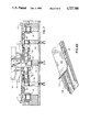
- FIGS. 5A and 5B are enlarged side elevations of the article support tray or carriage, showing it as it approaches the cams that actuate the tuck flap folding fingers and after the cams have actuated the folding fingers;
- FIGS. 8A and 8B are pictorial representations of the machine support surface, the article support carriage and the carton blank folding rails along the length of the machine.
- Aseptic containers C or other articles to be packaged, are shown being delivered to the machine by infeed conveyor 24.
- the articles move onto a support plate 26 until they are stopped by engagement with an upstanding lug 28.
- the support plate 26 is then raised to the dotted line position to lift up the containers resting on the support plate.
- the number of containers on the support plate will have been predetermined by the number of rows of containers being delivered by the conveyor, their dimensions, and the distance between the upstream end of the support plate and the stop lug 28, and will be the number of containers packaged in the carton.
- the conveyor 34 may comprise two spaced endless chains 36 trained over sprockets 38, one of which is powered as by drive belt 40.
- a number of article support trays or carriages 42 are supported at their sides by the chains 36 and are moved downstream along the upper working surface of the machine by the conveyor 34.
- the article support carriage 42 comprises a plurality of plates 70 attached at their ends to the conveyor chains 36. Extending up from the trailing end of the trailing plate 70 near each side edge of the plate is a small flange or lug 72 which engages and pushes against the trailing edge of the carton blank to ensure positive movement of the blank and to fix it in position for the folding tuck fingers.
- the trailing fingers 52 are attached to a cam follower 74 which is mounted to engage stationary cam 76. As shown in FIG. 8A, the cam 76 is fixed in position at the far side of the machine surface and the cam follower 74 is located on that side of the carriage so as to engage the cam.
- spring 84 is shown to bias the finger 52 toward its inactivated position so that when the cam follower 74 rides down off the cam 76, the folding finger 52 returns to the position depicted in FIG. 5A.
Landscapes
- Engineering & Computer Science (AREA)
- Mechanical Engineering (AREA)
- Container Filling Or Packaging Operations (AREA)
- Auxiliary Devices For And Details Of Packaging Control (AREA)
- Wrapping Of Specific Fragile Articles (AREA)
- Supplying Of Containers To The Packaging Station (AREA)
- Making Paper Articles (AREA)
- Pharmaceuticals Containing Other Organic And Inorganic Compounds (AREA)
- Orthopedics, Nursing, And Contraception (AREA)
- Extrusion Moulding Of Plastics Or The Like (AREA)
- Control And Other Processes For Unpacking Of Materials (AREA)
- Rear-View Mirror Devices That Are Mounted On The Exterior Of The Vehicle (AREA)
- Saccharide Compounds (AREA)
- Reciprocating, Oscillating Or Vibrating Motors (AREA)
Abstract
Description
Claims (13)
Priority Applications (17)
| Application Number | Priority Date | Filing Date | Title |
|---|---|---|---|
| US06/915,456 US4727708A (en) | 1986-10-06 | 1986-10-06 | Wrap-around packaging machine |
| DE8787906952T DE3776323D1 (en) | 1986-10-06 | 1987-09-08 | MACHINE TO COVER ITEMS. |
| BR8707476A BR8707476A (en) | 1986-10-06 | 1987-09-08 | APPARATUS AND PROCESS FOR PACKAGING A PLURALITY OF ARTICLES IN A CARDBOARD BOX |
| KR1019880700617A KR920004013B1 (en) | 1986-10-06 | 1987-09-08 | Wrap-around packaging machine |
| AT87906952T ATE71898T1 (en) | 1986-10-06 | 1987-09-08 | MACHINE FOR WRAPPING OBJECTS. |
| AU81041/87A AU585468B2 (en) | 1986-10-06 | 1987-09-08 | Wrap-around packaging machine |
| EP87906952A EP0285652B1 (en) | 1986-10-06 | 1987-09-08 | Wrap-around packaging machine |
| JP62506384A JPH0662126B2 (en) | 1986-10-06 | 1987-09-08 | Wrap around type packaging machine |
| PCT/US1987/002261 WO1988002333A1 (en) | 1986-10-06 | 1987-09-08 | Wrap-around packaging machine |
| IE245187A IE60513B1 (en) | 1986-10-06 | 1987-09-11 | Wrap-around packaging machine |
| NZ221800A NZ221800A (en) | 1986-10-06 | 1987-09-14 | Wrap-around packaging machine |
| ZA877080A ZA877080B (en) | 1986-10-06 | 1987-09-21 | Wrap-around packaging machine |
| ES8702852A ES2005379A6 (en) | 1986-10-06 | 1987-10-06 | Wrap-around packaging machine. |
| CA000548719A CA1272117A (en) | 1986-10-06 | 1987-10-06 | Wrap-around packaging machines |
| DK300088A DK168088B1 (en) | 1986-10-06 | 1988-06-02 | APPARATUS FOR PACKAGING MORE GOODS IN A COVER CARTON |
| FI882597A FI83752C (en) | 1986-10-06 | 1988-06-02 | INSLAGANDE FOERPACKNINGSMASKIN. |
| NO882477A NO168293C (en) | 1986-10-06 | 1988-06-03 | Wraparound PACKING MACHINE |
Applications Claiming Priority (1)
| Application Number | Priority Date | Filing Date | Title |
|---|---|---|---|
| US06/915,456 US4727708A (en) | 1986-10-06 | 1986-10-06 | Wrap-around packaging machine |
Publications (1)
| Publication Number | Publication Date |
|---|---|
| US4727708A true US4727708A (en) | 1988-03-01 |
Family
ID=25435771
Family Applications (1)
| Application Number | Title | Priority Date | Filing Date |
|---|---|---|---|
| US06/915,456 Expired - Lifetime US4727708A (en) | 1986-10-06 | 1986-10-06 | Wrap-around packaging machine |
Country Status (17)
| Country | Link |
|---|---|
| US (1) | US4727708A (en) |
| EP (1) | EP0285652B1 (en) |
| JP (1) | JPH0662126B2 (en) |
| KR (1) | KR920004013B1 (en) |
| AT (1) | ATE71898T1 (en) |
| AU (1) | AU585468B2 (en) |
| BR (1) | BR8707476A (en) |
| CA (1) | CA1272117A (en) |
| DE (1) | DE3776323D1 (en) |
| DK (1) | DK168088B1 (en) |
| ES (1) | ES2005379A6 (en) |
| FI (1) | FI83752C (en) |
| IE (1) | IE60513B1 (en) |
| NO (1) | NO168293C (en) |
| NZ (1) | NZ221800A (en) |
| WO (1) | WO1988002333A1 (en) |
| ZA (1) | ZA877080B (en) |
Cited By (16)
| Publication number | Priority date | Publication date | Assignee | Title |
|---|---|---|---|---|
| US5009053A (en) * | 1987-03-26 | 1991-04-23 | Keith A. Langenbeck | Storage and transport tray and tray packing system |
| US5148654A (en) * | 1990-06-05 | 1992-09-22 | Kisters Maschinenbau Gmbh | Packaging system |
| US5355657A (en) * | 1988-10-31 | 1994-10-18 | Pierre Chevalier | Article packaging machine |
| EP0654405A1 (en) * | 1993-11-24 | 1995-05-24 | Bocchiotti Societa'per L'industria Elettrotecnica S.P.A. | Method and machine for the semi-automatic packaging of rod-shaped objects in cardboard boxes starting from pre-cut cardboard blanks |
| US5660026A (en) * | 1995-11-02 | 1997-08-26 | Kraft Foods, Inc. | Method and apparatus for providing a package display case |
| EP0849176A1 (en) * | 1996-12-19 | 1998-06-24 | SMI S.p.A. | Apparatus for packaging containers in boxes, formed from a carton blank |
| US20130220774A1 (en) * | 2010-11-08 | 2013-08-29 | Krones Ag | Machine for processing and/or packaging objects and method for modifying a conveying section of this machine |
| WO2014117817A1 (en) * | 2013-01-29 | 2014-08-07 | Neopost Technologies | A method and system for automatically forming packaging boxes |
| WO2014117820A1 (en) * | 2013-01-29 | 2014-08-07 | Neopost Technologies | A method and system for automatically forming packaging boxes |
| DE102015211955A1 (en) * | 2015-06-26 | 2016-12-29 | Krones Aktiengesellschaft | Working device and method for transporting and folding carton blanks |
| DE102015120627A1 (en) * | 2015-11-27 | 2017-06-01 | Krones Aktiengesellschaft | Working device and method for transporting and folding carton blanks with at least one endlessly circulating back conveyor chain |
| US20170157880A1 (en) * | 2013-09-27 | 2017-06-08 | Jens Eckermann | Machine and method for folding and adhesively bonding blanks for the production of folding boxes |
| ITUA20163736A1 (en) * | 2016-05-24 | 2017-11-24 | F L Auto Srl | BENDING STATION FOR BENDING A PACKAGING CARDBOARD AROUND A ARTICLE SUPPORTED ON THE CARTON AND MACHINE FOR PACKING AN ARTICLE INSIDE A CARDBOARD BOX OBTAINED FROM A PACKING CARDBOARD |
| WO2019195210A1 (en) * | 2018-04-05 | 2019-10-10 | Graphic Packaging International, Llc | Packaging machine with carton feeding system |
| EP3549879B1 (en) | 2018-03-07 | 2021-05-12 | Krones Aktiengesellschaft | Packaging device for articles and method for preparing flat packaging blanks for articles |
| US11279503B2 (en) * | 2017-08-03 | 2022-03-22 | Panotec S.R.L. | Plant for automated packaging of items in cardboard boxes |
Families Citing this family (4)
| Publication number | Priority date | Publication date | Assignee | Title |
|---|---|---|---|---|
| IT1233320B (en) * | 1989-07-19 | 1992-03-26 | Baumer Srl | IMPROVEMENT OF MACHINES FOR THE PACKAGING OF GROUPS OF ARTICLES IN BOXES AND PARTICULARLY OF JARS, BOTTLES AND SIMILAR CONTAINERS |
| FI97355C (en) * | 1995-01-04 | 1996-12-10 | Jopamac Ab Oy | Apparatus for packaging of stacked paper goods |
| KR101501768B1 (en) * | 2013-07-29 | 2015-03-10 | (주)진성 테크템 | Wrap around caser continuously bundling the numerous bottles |
| KR101864432B1 (en) | 2016-11-30 | 2018-06-04 | (주)진성 테크템 | Continuous automatic wrap around packing machine of cubic package |
Citations (7)
| Publication number | Priority date | Publication date | Assignee | Title |
|---|---|---|---|---|
| US2932929A (en) * | 1959-01-08 | 1960-04-19 | Burgermeister Brewing Corp | Tray packing and forming machine |
| US3555776A (en) * | 1966-05-04 | 1971-01-19 | Johns Nigrelli Johns | Machine for forming a tray around a group of articles |
| US3673763A (en) * | 1970-06-26 | 1972-07-04 | Grand City Container Corp | Carton erecting and packaging machine |
| US3866392A (en) * | 1972-05-11 | 1975-02-18 | Dufaylite Dev Ltd | Packaging apparatus |
| US4030268A (en) * | 1975-07-18 | 1977-06-21 | Thurne Engineering Company Limited | Packaging machine |
| US4343129A (en) * | 1976-04-27 | 1982-08-10 | G.B.R., Ltd. | Mechanism of making an envelope |
| US4571916A (en) * | 1983-12-05 | 1986-02-25 | Southern Tool Company | Secondary packaging machine |
Family Cites Families (4)
| Publication number | Priority date | Publication date | Assignee | Title |
|---|---|---|---|---|
| US3866391A (en) * | 1973-02-20 | 1975-02-18 | Emhart Corp | Wrap-around packer |
| JPS53149493A (en) * | 1977-05-28 | 1978-12-26 | Kyoto Seisakusho | Method of and apparatus for placing collective article |
| US4215525A (en) * | 1978-05-16 | 1980-08-05 | Johns-Nigrelli-Johns | Tray forming machine |
| US4314785A (en) * | 1979-12-26 | 1982-02-09 | Package Machinery Company | Stacking and packaging apparatus |
-
1986
- 1986-10-06 US US06/915,456 patent/US4727708A/en not_active Expired - Lifetime
-
1987
- 1987-09-08 DE DE8787906952T patent/DE3776323D1/en not_active Expired - Fee Related
- 1987-09-08 BR BR8707476A patent/BR8707476A/en not_active IP Right Cessation
- 1987-09-08 AT AT87906952T patent/ATE71898T1/en not_active IP Right Cessation
- 1987-09-08 JP JP62506384A patent/JPH0662126B2/en not_active Expired - Fee Related
- 1987-09-08 KR KR1019880700617A patent/KR920004013B1/en not_active Expired
- 1987-09-08 EP EP87906952A patent/EP0285652B1/en not_active Expired - Lifetime
- 1987-09-08 AU AU81041/87A patent/AU585468B2/en not_active Ceased
- 1987-09-08 WO PCT/US1987/002261 patent/WO1988002333A1/en not_active Ceased
- 1987-09-11 IE IE245187A patent/IE60513B1/en not_active IP Right Cessation
- 1987-09-14 NZ NZ221800A patent/NZ221800A/en unknown
- 1987-09-21 ZA ZA877080A patent/ZA877080B/en unknown
- 1987-10-06 CA CA000548719A patent/CA1272117A/en not_active Expired - Lifetime
- 1987-10-06 ES ES8702852A patent/ES2005379A6/en not_active Expired
-
1988
- 1988-06-02 FI FI882597A patent/FI83752C/en not_active IP Right Cessation
- 1988-06-02 DK DK300088A patent/DK168088B1/en not_active IP Right Cessation
- 1988-06-03 NO NO882477A patent/NO168293C/en unknown
Patent Citations (7)
| Publication number | Priority date | Publication date | Assignee | Title |
|---|---|---|---|---|
| US2932929A (en) * | 1959-01-08 | 1960-04-19 | Burgermeister Brewing Corp | Tray packing and forming machine |
| US3555776A (en) * | 1966-05-04 | 1971-01-19 | Johns Nigrelli Johns | Machine for forming a tray around a group of articles |
| US3673763A (en) * | 1970-06-26 | 1972-07-04 | Grand City Container Corp | Carton erecting and packaging machine |
| US3866392A (en) * | 1972-05-11 | 1975-02-18 | Dufaylite Dev Ltd | Packaging apparatus |
| US4030268A (en) * | 1975-07-18 | 1977-06-21 | Thurne Engineering Company Limited | Packaging machine |
| US4343129A (en) * | 1976-04-27 | 1982-08-10 | G.B.R., Ltd. | Mechanism of making an envelope |
| US4571916A (en) * | 1983-12-05 | 1986-02-25 | Southern Tool Company | Secondary packaging machine |
Cited By (26)
| Publication number | Priority date | Publication date | Assignee | Title |
|---|---|---|---|---|
| US5009053A (en) * | 1987-03-26 | 1991-04-23 | Keith A. Langenbeck | Storage and transport tray and tray packing system |
| US5355657A (en) * | 1988-10-31 | 1994-10-18 | Pierre Chevalier | Article packaging machine |
| US5148654A (en) * | 1990-06-05 | 1992-09-22 | Kisters Maschinenbau Gmbh | Packaging system |
| EP0654405A1 (en) * | 1993-11-24 | 1995-05-24 | Bocchiotti Societa'per L'industria Elettrotecnica S.P.A. | Method and machine for the semi-automatic packaging of rod-shaped objects in cardboard boxes starting from pre-cut cardboard blanks |
| US5660026A (en) * | 1995-11-02 | 1997-08-26 | Kraft Foods, Inc. | Method and apparatus for providing a package display case |
| EP0849176A1 (en) * | 1996-12-19 | 1998-06-24 | SMI S.p.A. | Apparatus for packaging containers in boxes, formed from a carton blank |
| US9637314B2 (en) | 2010-11-08 | 2017-05-02 | Krones Aktiengesellschaft | Machine for processing and/or packaging objects and method for modifying a conveying section of this machine |
| US9394113B2 (en) * | 2010-11-08 | 2016-07-19 | Krones Ag | Machine for processing and/or packaging objects and method for modifying a conveying section of this machine |
| US20130220774A1 (en) * | 2010-11-08 | 2013-08-29 | Krones Ag | Machine for processing and/or packaging objects and method for modifying a conveying section of this machine |
| WO2014117820A1 (en) * | 2013-01-29 | 2014-08-07 | Neopost Technologies | A method and system for automatically forming packaging boxes |
| US20150367974A1 (en) * | 2013-01-29 | 2015-12-24 | Neopost Technologies | Method and system for automatically forming packaging boxes |
| WO2014117817A1 (en) * | 2013-01-29 | 2014-08-07 | Neopost Technologies | A method and system for automatically forming packaging boxes |
| US10543945B2 (en) * | 2013-01-29 | 2020-01-28 | Neopost Technologies | Method and system for automatically forming packaging boxes |
| US10507944B2 (en) * | 2013-09-27 | 2019-12-17 | Krones Ag | Machine and method for folding and adhesively bonding blanks for the production of folding boxes |
| US20170157880A1 (en) * | 2013-09-27 | 2017-06-08 | Jens Eckermann | Machine and method for folding and adhesively bonding blanks for the production of folding boxes |
| DE102015211955A1 (en) * | 2015-06-26 | 2016-12-29 | Krones Aktiengesellschaft | Working device and method for transporting and folding carton blanks |
| DE102015120627A1 (en) * | 2015-11-27 | 2017-06-01 | Krones Aktiengesellschaft | Working device and method for transporting and folding carton blanks with at least one endlessly circulating back conveyor chain |
| WO2017203399A1 (en) * | 2016-05-24 | 2017-11-30 | F.L. Auto S.R.L. | A folding station of a cardboard blank for packing an article rested on the cardboard blank and a machine for packaging an article internally of a cardboard box obtained from the cardboard blank |
| CN109476400A (en) * | 2016-05-24 | 2019-03-15 | Fl自动化有限责任公司 | A folding station for cardboard blanks, a machine for packaging articles resting on cardboard blanks, and a machine for packaging articles inside cardboard boxes obtained from cardboard blanks |
| ITUA20163736A1 (en) * | 2016-05-24 | 2017-11-24 | F L Auto Srl | BENDING STATION FOR BENDING A PACKAGING CARDBOARD AROUND A ARTICLE SUPPORTED ON THE CARTON AND MACHINE FOR PACKING AN ARTICLE INSIDE A CARDBOARD BOX OBTAINED FROM A PACKING CARDBOARD |
| CN109476400B (en) * | 2016-05-24 | 2020-06-23 | Fl自动化有限责任公司 | Folding station for cardboard blanks and machines for packing items inside cardboard boxes |
| US11059254B2 (en) * | 2016-05-24 | 2021-07-13 | F.L. Auto S.R.L. | Folding station of a cardboard blank for packing an article rested on the cardboard blank and a machine for packaging an article internally of a cardboard box obtained from the cardboard blank |
| US11279503B2 (en) * | 2017-08-03 | 2022-03-22 | Panotec S.R.L. | Plant for automated packaging of items in cardboard boxes |
| EP3549879B1 (en) | 2018-03-07 | 2021-05-12 | Krones Aktiengesellschaft | Packaging device for articles and method for preparing flat packaging blanks for articles |
| WO2019195210A1 (en) * | 2018-04-05 | 2019-10-10 | Graphic Packaging International, Llc | Packaging machine with carton feeding system |
| US11167870B2 (en) | 2018-04-05 | 2021-11-09 | Graphic Packaging International, Llc | Packaging machine with carton feeding system |
Also Published As
| Publication number | Publication date |
|---|---|
| DK300088D0 (en) | 1988-06-02 |
| NZ221800A (en) | 1989-01-27 |
| NO168293B (en) | 1991-10-28 |
| NO168293C (en) | 1992-02-05 |
| ES2005379A6 (en) | 1989-03-01 |
| EP0285652A4 (en) | 1989-02-02 |
| CA1272117A (en) | 1990-07-31 |
| IE872451L (en) | 1988-04-06 |
| AU585468B2 (en) | 1989-06-15 |
| JPH0662126B2 (en) | 1994-08-17 |
| DK168088B1 (en) | 1994-02-07 |
| EP0285652A1 (en) | 1988-10-12 |
| NO882477D0 (en) | 1988-06-03 |
| BR8707476A (en) | 1988-12-06 |
| DE3776323D1 (en) | 1992-03-05 |
| AU8104187A (en) | 1988-04-21 |
| IE60513B1 (en) | 1994-07-27 |
| JPH01501058A (en) | 1989-04-13 |
| WO1988002333A1 (en) | 1988-04-07 |
| FI83752B (en) | 1991-05-15 |
| DK300088A (en) | 1988-06-02 |
| KR920004013B1 (en) | 1992-05-22 |
| FI83752C (en) | 1991-08-26 |
| FI882597L (en) | 1988-06-02 |
| EP0285652B1 (en) | 1992-01-22 |
| KR880701664A (en) | 1988-11-04 |
| NO882477L (en) | 1988-06-03 |
| ZA877080B (en) | 1988-05-25 |
| FI882597A0 (en) | 1988-06-02 |
| ATE71898T1 (en) | 1992-02-15 |
Similar Documents
| Publication | Publication Date | Title |
|---|---|---|
| US4727708A (en) | Wrap-around packaging machine | |
| US5531661A (en) | Carrier sleeve erecting apparatus and method | |
| EP0268611B1 (en) | Method and apparatus for feeding containers to a carrier sleeve | |
| US4296590A (en) | Method and apparatus for conveying six-pack containers to carton blank | |
| US3585776A (en) | Process and apparatus for manufacturing a box completely filled with a stack of articles | |
| US4709538A (en) | Apparatus for feeding and opening a beverage carrier | |
| US4571916A (en) | Secondary packaging machine | |
| FI84457C (en) | Folding mechanism for dust flap for use in the design of cover wrappers of the type of cover | |
| US3543474A (en) | Gusset forming machine | |
| GB2141093A (en) | Erecting trays about their contents | |
| US3842570A (en) | High speed tray former and loader | |
| US3454149A (en) | Blank conveying apparatus and method | |
| EP0325638B1 (en) | Tray carton end flap auxiliary sealer |
Legal Events
| Date | Code | Title | Description |
|---|---|---|---|
| AS | Assignment |
Owner name: MANVILLE CORPORATION, KEN-CARYL RANCH, JEFFERSON C Free format text: ASSIGNMENT OF ASSIGNORS INTEREST.;ASSIGNORS:CONFORTO, PETER M.;INGRAM, STEVEN G.;REEL/FRAME:004640/0833 Effective date: 19861202 Owner name: MANVILLE CORPORATION,COLORADO Free format text: ASSIGNMENT OF ASSIGNORS INTEREST;ASSIGNORS:CONFORTO, PETER M.;INGRAM, STEVEN G.;REEL/FRAME:004640/0833 Effective date: 19861202 |
|
| STCF | Information on status: patent grant |
Free format text: PATENTED CASE |
|
| FEPP | Fee payment procedure |
Free format text: PAYOR NUMBER ASSIGNED (ORIGINAL EVENT CODE: ASPN); ENTITY STATUS OF PATENT OWNER: LARGE ENTITY |
|
| AS | Assignment |
Owner name: MANVILLE FOREST PRODUCTS CORPORATION, A CORP. OF D Free format text: ASSIGNMENT OF ASSIGNORS INTEREST.;ASSIGNOR:MANVILLE CORPORATION;REEL/FRAME:005594/0381 Effective date: 19901231 |
|
| AS | Assignment |
Owner name: RIVERWOOD INTERNATIONAL CORPORATION Free format text: CHANGE OF NAME;ASSIGNOR:MANVILLE FOREST PRODUCTS, CORPORATION (CHANGED TO);REEL/FRAME:005791/0252 Effective date: 19910610 |
|
| FPAY | Fee payment |
Year of fee payment: 4 |
|
| AS | Assignment |
Owner name: RIVERWOOD NATURAL RESOURCES CORPORATION, A DE CORP Free format text: ASSIGNMENT OF ASSIGNORS INTEREST.;ASSIGNOR:RIVERWOOD INTERNATIONAL CORPORATION;REEL/FRAME:006135/0040 Effective date: 19911223 |
|
| AS | Assignment |
Owner name: RIVERWOOD INTERNATIONAL CORPORATION, GEORGIA Free format text: CHANGE OF NAME;ASSIGNOR:RIVERWOOD NATURAL RESOURCES CORPORATION;REEL/FRAME:006325/0131 Effective date: 19920325 |
|
| FPAY | Fee payment |
Year of fee payment: 8 |
|
| AS | Assignment |
Owner name: CHEMICAL BANK, AS ADMINISTRATIVE AGENT, NEW YORK Free format text: SECURITY INTEREST;ASSIGNOR:RIVERWOOD INTERNATIONAL USA, INC.;REEL/FRAME:007961/0164 Effective date: 19960328 Owner name: RIVERWOOD INTERNATIONAL USA, INC., GEORGIA Free format text: ASSIGNMENT OF ASSIGNORS INTEREST;ASSIGNOR:RIVERWOOD INTERNATIONAL CORPORATION;REEL/FRAME:007927/0768 Effective date: 19960328 |
|
| FPAY | Fee payment |
Year of fee payment: 12 |
|
| AS | Assignment |
Owner name: THE CHASE MANHATTAN BANK, AS ADMINISTRATIVE AGENT, Free format text: SECURITY INTEREST;ASSIGNOR:RIVERWOOD INTERNATIONAL CORPORATION (DE CORPORATION);REEL/FRAME:012243/0374 Effective date: 20010827 |
|
| AS | Assignment |
Owner name: RIVERWOOD INTERNATIONAL CORPORATION, GEORGIA Free format text: TERMINATION AND RELEASE OF SECURITY INTEREST IN PATENTS;ASSIGNOR:JPMORGAN CHASE BANK, AS ADMINISTRATIVE AGENT;REEL/FRAME:014363/0613 Effective date: 20030808 |
|
| AS | Assignment |
Owner name: GRAPHIC PACKAGING INTERNATIONAL, INC., GEORGIA Free format text: MERGER AND CHANGE OF NAME;ASSIGNORS:GRAPHIC PACKAGING INTERNATIONAL, INC.;RIVERWOOD INTERNATIONAL CORPORATION;REEL/FRAME:014409/0295 Effective date: 20030808 |
|
| AS | Assignment |
Owner name: JPMORGAN CHASE BANK, AS ADMINISTRATIVE AGENT, TEXAS Free format text: SECURITY INTEREST;ASSIGNOR:GRAPHIC PACKAGING INTERNATIONAL, INC.;REEL/FRAME:014074/0162 Effective date: 20030808 Owner name: JPMORGAN CHASE BANK, AS ADMINISTRATIVE AGENT, TEXAS Free format text: INVALID RECORDING. PLEASE SEE RECORDING AT REEL 014074, FRAME 0162;ASSIGNOR:GRAPHIC PACKAGING INTERNATIONAL, INC. (DE CORPORATION);REEL/FRAME:014066/0194 Effective date: 20030808 Owner name: JPMORGAN CHASE BANK, AS ADMINISTRATIVE AGENT, TEXA Free format text: INVALID RECORDING. PLEASE;ASSIGNOR:GRAPHIC PACKAGING INTERNATIONAL, INC. (DE CORPORATION);REEL/FRAME:014066/0194 Effective date: 20030808 Owner name: JPMORGAN CHASE BANK, AS ADMINISTRATIVE AGENT, TEXA Free format text: SECURITY INTEREST;ASSIGNOR:GRAPHIC PACKAGING INTERNATIONAL, INC.;REEL/FRAME:014074/0162 Effective date: 20030808 Owner name: JPMORGAN CHASE BANK, AS ADMINISTRATIVE AGENT, TEXA Free format text: INVALID RECORDING. PLEASE SEE RECORDING AT REEL 014074, FRAME 0162;ASSIGNOR:GRAPHIC PACKAGING INTERNATIONAL, INC. (DE CORPORATION);REEL/FRAME:014066/0194 Effective date: 20030808 Owner name: JPMORGAN CHASE BANK, AS ADMINISTRATIVE AGENT, TEXAS Free format text: INVALID RECORDING. PLEASE SEE RECORDING AT REEL 014074, FRAME 0162.;ASSIGNOR:GRAPHIC PACKAGING INTERNATIONAL, INC. (DE CORPORATION);REEL/FRAME:014066/0194 Effective date: 20030808 |
|
| AS | Assignment |
Owner name: GRAPHIC PACKAGING INTERNATIONAL, INC., GEORGIA Free format text: TERMINATION OF SECURITY INTEREST;ASSIGNOR:JPMORGAN CHASE BANK, N.A., A NATIONAL BANKING ASSOCIATION;REEL/FRAME:019341/0940 Effective date: 20070516 |