US4723931A - Toy action figure with accessory-attaching capability - Google Patents
Toy action figure with accessory-attaching capability Download PDFInfo
- Publication number
- US4723931A US4723931A US06/826,410 US82641086A US4723931A US 4723931 A US4723931 A US 4723931A US 82641086 A US82641086 A US 82641086A US 4723931 A US4723931 A US 4723931A
- Authority
- US
- United States
- Prior art keywords
- receptor
- holes
- coupling mechanism
- pin
- press
- Prior art date
- Legal status (The legal status is an assumption and is not a legal conclusion. Google has not performed a legal analysis and makes no representation as to the accuracy of the status listed.)
- Expired - Lifetime
Links
- 230000008878 coupling Effects 0.000 claims abstract description 55
- 238000010168 coupling process Methods 0.000 claims abstract description 55
- 238000005859 coupling reaction Methods 0.000 claims abstract description 55
- 238000003780 insertion Methods 0.000 claims description 3
- 230000037431 insertion Effects 0.000 claims description 3
- 230000004308 accommodation Effects 0.000 claims 3
- 239000004033 plastic Substances 0.000 abstract description 4
- 229920003023 plastic Polymers 0.000 abstract description 4
- 230000001815 facial effect Effects 0.000 abstract description 2
- 102000005962 receptors Human genes 0.000 description 87
- 210000002414 leg Anatomy 0.000 description 9
- 230000033001 locomotion Effects 0.000 description 8
- 239000002131 composite material Substances 0.000 description 7
- 238000010276 construction Methods 0.000 description 4
- 239000000463 material Substances 0.000 description 3
- 230000000694 effects Effects 0.000 description 2
- 210000000629 knee joint Anatomy 0.000 description 2
- 230000014759 maintenance of location Effects 0.000 description 2
- 238000000465 moulding Methods 0.000 description 2
- 230000000717 retained effect Effects 0.000 description 2
- 102000016979 Other receptors Human genes 0.000 description 1
- DHKHKXVYLBGOIT-UHFFFAOYSA-N acetaldehyde Diethyl Acetal Natural products CCOC(C)OCC DHKHKXVYLBGOIT-UHFFFAOYSA-N 0.000 description 1
- 125000002777 acetyl group Chemical class [H]C([H])([H])C(*)=O 0.000 description 1
- 239000000853 adhesive Substances 0.000 description 1
- 230000001070 adhesive effect Effects 0.000 description 1
- 230000009286 beneficial effect Effects 0.000 description 1
- 230000015572 biosynthetic process Effects 0.000 description 1
- 230000026058 directional locomotion Effects 0.000 description 1
- 230000002708 enhancing effect Effects 0.000 description 1
- 210000003414 extremity Anatomy 0.000 description 1
- 210000000245 forearm Anatomy 0.000 description 1
- 229920005669 high impact polystyrene Polymers 0.000 description 1
- 239000004797 high-impact polystyrene Substances 0.000 description 1
- 230000005923 long-lasting effect Effects 0.000 description 1
- 238000004519 manufacturing process Methods 0.000 description 1
- 230000013011 mating Effects 0.000 description 1
- 229920000915 polyvinyl chloride Polymers 0.000 description 1
- 239000004800 polyvinyl chloride Substances 0.000 description 1
- 230000003068 static effect Effects 0.000 description 1
Images


Classifications
-
- A—HUMAN NECESSITIES
- A63—SPORTS; GAMES; AMUSEMENTS
- A63H—TOYS, e.g. TOPS, DOLLS, HOOPS OR BUILDING BLOCKS
- A63H3/00—Dolls
- A63H3/16—Dolls made of parts that can be put together
-
- A—HUMAN NECESSITIES
- A63—SPORTS; GAMES; AMUSEMENTS
- A63H—TOYS, e.g. TOPS, DOLLS, HOOPS OR BUILDING BLOCKS
- A63H3/00—Dolls
- A63H3/28—Arrangements of sound-producing means in dolls; Means in dolls for producing sounds
-
- A—HUMAN NECESSITIES
- A63—SPORTS; GAMES; AMUSEMENTS
- A63H—TOYS, e.g. TOPS, DOLLS, HOOPS OR BUILDING BLOCKS
- A63H33/00—Other toys
- A63H33/003—Convertible toys, e.g. robots convertible into rockets or vehicles convertible into planes
Definitions
- This invention relates generally to toy action figures, and pertains more particularly to such a figure to which various accessories can be releasably attached.
- a general object of the invention is to provide a toy action figure having a futuristic appearance to which various accessories can be added so that the child can create its own combinations and which allows the child to originate various battle modes through the agency of accessories simulating a variety of weapons and propulsion devices. In this way, the child can use its imagination in deriving various space age mission systems and effectuating fanciful air, sea and land battle strategies.
- a more specific object of the invention is to provide a toy action figure in which its accessory-attaching capability is realized through the agency of specially configured press-in pins that are mounted on the various accessories to be releasably attached to the more basic toy action figure.
- the toy action figure is provided with a number of receptor holes in which the pins can be inserted to effect the releasable attachment of the particular accessory.
- an aim of the invention is to provide a toy action figure that will make use of press-in pins associated with the various accessories to be attached, each pin being sufficiently compliant so that it can be pushed straight into any of a number of receptor holes and also pulled straight out of such holes, both directional movements being manually achievable without exceeding acceptable force limits.
- Yet another object of the invention is to give the child a choice as to the type of add-on accessory he or she wishes to combine with the more basic toy action figure.
- the child may snap onto the figure a particular accessory that is to be rotated via a coupling mechanism extending forwardly through the figure's torso, or on the other hand the child can elect to add an accessory that remains stationary once it has been attached to the toy figure.
- an object of the invention is to provide a coupling mechanism within the torso of the toy figure that has included therein an overload feature so that excessive manual twisting or torsional forces used to effect an animated result cannot be applied to the figure in such a way and with such magnitude as to break some of the components.
- a mechanism for transmitting rotary movement through the figure's torso is provided with interfitting face-to-face sawteeth or serrations that are normally urged into engagement by a resilient coil spring and which teeth or serrations will automatically disengage, the coil spring permitting this, when too much twisting force is employed.
- Another object is to provide a basic toy figure that will be rugged and long lasting, yet possessing a sufficient amount of variety and animation capability so that it will maintain the interest of the child over a considerable period of time.
- the invention also has for an object the mass producing of toy figures in accordance with the invention which toy figures can be fabricated and sold at a comparatively low price, thereby encouraging the widespread purchase and use of figures of this type, the relatively low manufacturing costs per item allowing a rather large assortment of various accessories to be made available that can be snapped into position in conjunction with certain basic action figures.
- toy action figure of composite design in which one half can be attached to another half via compliant pins so that unusual toy configurations can be created by the child.
- one portion of the composite toy figure can represent a human being and the other half, say, a machine.
- each receptor hole is formed with a bore having a recessed annular internal rib located inwardly from the entrance of the bore so that a specially configured press-in or mating pin, the pin having a circumferential groove and a compliance slot, can be pressed into a selected receptor hole so that the resulting snap fit will retain the particular accessory in place until deliberately removed by the child.
- receptor holes in the ends of a coupling mechanism be physically oriented in a predetermined relationship with respect to the receptor holes in the toy figure's torso.
- the child is afforded the opportunity of selecting accessories to be attached to the coupling mechanism so that one accessory can be used to drivingly rotate the coupling mechanism and a second accessory be drivenly rotated by the coupling mechanism, the particular receptor hole patterns in the torso itself which are located in the vicinity of the receptor holes provided in the coupling ends enabling even relatively large accessories to be attached.
- the transmitted rotation through the agency of the coupling mechanism can be converted into other motions.
- the child can add to a rather basic toy action figure a number of accessories, some of which can be of an animated character and others of which will simply be attached to the figure without any relative movement.
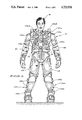
- FIG. 1 is a front elevational view of a toy action figure without any accessories having been attached thereto;
- FIG. 2 is a rear elevational view of the toy figure appearing in FIG. 1, this view also being without accessories;
- FIG. 3 is a side elevational view taken from the right of FIG. 1;
- FIG. 4 is a vertical sectional view taken in the direction of line 4--4 of FIG. 1 for the purpose of illustrating a coupling mechanism extending forwardly through the torso, as well as illustrating the configuration of certain receptor holes;
- FIG. 5 is a vertical sectional view taken in the direction of line 5--5 of FIG. 4 for the purpose of further illustrating the construction of the coupling mechanism, the view also depicting a U-shaped pawl-type element for producing a clicking sound when the coupling mechanism is rotated and the view additionally showing a rearwardly disposed light shield that prevents light from passing through the torso via the various receptor holes located in the front and rear portions of the torso;
- FIG. 6 is a side elevational view corresponding to FIG. 3 but with accessories plugged into the toy figure;
- FIG. 7 is a side elevational view corresponding to FIG. 6 but with the accessories shown in an exploded or detached relationship;
- FIG. 8 is a greatly enlarged sectional view taken in the direction of line 8--8 of FIG. 7 in order to show the cross sectional makeup of a press-in pin;
- FIG. 9 is a vertical sectional detail taken in the direction of line 9--9 of FIG. 6 in order to show how a press-in pin integrally projecting from a simulated missile launcher is releasably held in a receptor hole, the launcher being viewed from the rear;
- FIG. 10 is an exploded view corresponding to FIG. 9, the view being on a slightly reduced scale
- FIG. 11 is a horizontal sectional detail taken in the direction of line 11--11 of FIG. 6;
- FIG. 12 is an enlarged sectional view taken in the direction of line 12--12 of FIG. 9, the view depicting how the press-in pin is contained within the receptor hole;
- FIG. 13 is a side elevational view of the launcher looking directly at the free end of the press-in pin;
- FIG. 14 is a front elevational view of a composite toy action figure in the form of a combined man and machine.
- FIG. 15 is an open face exploded view of the composite man and machine of FIG. 14.
- the toy FIG. 10 comprises a hollow torso 12 composed of a front shell 14 and a rear shell 16.
- the toy figure also includes a head 18, arms 20 and legs 22.
- a feature providing an animated movement includes therein a drum-like coupling mechanism 24 comprised of a housing 26 which is formed from forward and rear shells 28 and 30, respectively, which are sealed together at 32 to render the housing 26 unitary.
- the forward shell 28 includes a cylindrical portion 34, an inturned flange or annular face plate portion 36 having a circular central opening 38.
- Formed integrally on the inturned flange or annular plate portion 36 is a set of inwardly facing sawteeth or serrations 40, the teeth or serrations 40 being angularly spaced throughout a complete circle on the inner side of the portion 36.
- the coupling mechanism 24 additionally includes a driven hub unit 42 having a cup-shaped end residing within the housing 26, more specifically within the shell 28 thereof, and including a relatively large diameter cylindrical portion labeled 44 and an annular inturned flange or annular face plate portion 46, the plate 46 having formed thereon a second set of sawteeth or serrations 48 which are outwardly facing and which are normally urged into engagement with the sawteeth or serrations 40 by means yet to be described.
- the annular inturned flange or face plate portion 46 has a tubular hub 50 integral therewith, the tubular hub 50 having a cylindrical outer surface at 52 that is journaled in the circular opening 53 provided in the forward shell 14 of the torso 12.
- the tubular hub 50 is formed with a receptor hole 51 having a hexagonal bore portion 54 extending inwardly from its entrance, that is, from the right toward the left as viewed in FIG. 4.
- the receptor hole 51 also has an inner cylindrical bore portion 56.
- Intermediate the bore portions 54, 56 is an internal annular rib 58.
- the rear shell 30 constitutes a driving hub unit in that it includes a first cylindrical portion 60 that is secured, such as with a suitable adhesive, to the cylindrical portion 34 of the shell 28 to make the housing 26 of unitary construction.
- a second cylindrical portion 62 that is stepped inwardly somewhat from the cylindrical portion 60.
- Formed on the second cylindrical portion 62 is a series of circumferentially extending sawteeth 64, the angularly spaced sawteeth 64 extending completely around the cylindrical portion 62 for a purpose that will become manifest hereinafter.
- the rear shell 30 that constitutes a driving hub unit also includes an annular inturned flange or annular plate portion 66 that extends inwardly from the cylindrical portion 62.
- a tubular hub 68 is integral with the annular plate portion 66, the tubular hub 68 having a receptor hole 69 formed with a bore portion 70 of hexagonal cross section extending inwardly from the bore's entrance.
- the receptor hole 69 also has a cylindrical inner bore portion 72. Between the two bore portions 70 and 72 is an internal annular rib 74.
- the tubular hub 68 has a cylindrical outer surface 76 that is journaled for rotation in a circular opening 78 located in the rear shell 16, the opening 78 functionally corresponding to the earlier-mentioned opening 53.
- the sawteeth or serrations 48 which are integral with the flange or annular plate portion 46, are normally urged into engagement with the sawteeth or serrations 40, which are integral with the flange or annular face plate portion 36, by means of a somewhat compressed coil spring 79.
- the left end of the coil spring 79 reactively bears against the annular portion 66 and the right end bears against the annular portion 46, the coil spring 79 in this way yieldingly biasing the two sets of sawteeth 48 and 40 into engagement.
- FIGS. 6 and 7 an accessory 80 in the form of a space age rudder serves as a key for twisting or rotating the previously mentioned coupling mechanism 24.
- the accessory 80 includes a press-in pin 82 that is integral therewith.
- the press-in pin 82 includes a hexagonal portion 84, a tapered or conical portion 86 and an intermediate circumferential groove 88.
- a longitudinal slot 90 having a bottom or base 92, as best understood from FIG. 8 (and also from FIG. 12 depicting an identical press-in pin 82c yet to be referred to).
- the bottom or base 92 as can also be seen in FIG.
- the slot 90 has a thickness equal to approximately one quarter of the diameter of the press-in pin 82; in other words the slot 90 has a depth equal to approximately three fourths of the diameter of the pin 82. Still further, it should be noted that the slot 90 is formed with diverging sidewalls which can be flexed toward each other to narrow the slot 90 in a manner that will become evident hereinafter.
- the longitudinal slot 90 renders the pin sufficiently compliant so that it can be easily inserted and withdrawn from any one of a number of selected receptor holes, including the two already identified by the reference numerals 51 and 69, plus those yet to be referred to.
- the slot 90 imparts a sufficient amount of compliancy to the press-in pin 82 so that it will be retained in place once inserted into any one of a number of receptor holes that might be selected.
- only the receptor holes 51 and 69 have been referred to up to this point.
- a winged accessory 96 comprised of a hollow housing 98 and a pair of pivotal wings 100, there being one wing 100 visible in FIG. 7 (the other wing being on the far side of the housing 98 and thus concealed from view).
- the mechanism has been indicated generally by the numeral 102, including a drive hub 104 that is like the previously mentioned tubular hubs 50 and 68 in that it includes a hexagonal bore portion (not shown) into which the hexagonal portion 84 of the press-in pin 82 is received.
- the coupling mechanism 102 additionally includes a driven pin 106 that projects from the housing 98, having a hexagonal portion 108 that provides a longitudinal slip fit when inserted into the hexagonal bore portion 70 of the tubular hub 68 belonging to the coupling mechanism 24 that extends forwardly through the torso 12.
- the interfitting hexagonal portion 108 within the hexagonal portion 70 prevents any relative rotation between the pin 106 and the tubular hub 68. Owing to the hexagonal portion 84 on the press-in pin 82 and the complementally configured hexagonal bore portion (not illustrated) formed in the drive hub 104 of the coupling mechanism 102, relative rotation is precluded between the pin 82 and the coupling mechanism 102.
- the two guide pins 110 are arranged on another diagonal line which includes the visible guide pin 110, and the driven pin 106 plus the obscured guide pin 110.
- the guide pins 110 are both of relatively simple configuration in that they do not perform any retention function as do the press-in pins 82a. Thus, there are five pins (the pin 106, the two pins 82a and the two pins 110) projecting from the winged accessory 96. However, the overall roles played by these pins 106, 82a and 110 will perhaps be better appreciated when a specific hole pattern is hereinafter referred to that is provided in the rear torso shell 16.
- a make-believe sensing accessory 112 that has a press-in pin 82b that is identical to the previously mentioned press-in pins 82 and 82a.
- the press-in pin 82b is releasably retained within the receptor hole 69 in the tubular hub 68 of the coupling mechanism 24.
- the rudder accessory 80 owing to the hexagonal portion 84 on its press-in pin 82, when twisted, produces a rotative movement of the coupling mechanism 102 because the hexagonal portion 84 fits within the hexagonal bore portion (not shown) contained in the hub 104 belonging to the coupling mechanism 102.
- the rotary motion of the coupling mechanism 102 which is contained in the winged accessory 96, causes the coupling mechanism 24 to rotate due to the interfitting of the hexagonal portion 108 of the pin 106 within the hexagonal bore portion 70 of the hub 68.
- the press-in pin 82 on the rudder accessory 80 could, if desired, be inserted directly into the receptor hole 69 belonging to the tubular hub 68 of the coupling mechanism 24, or if the child chooses to do so, the press-in pin 82 on the rudder accessory 80 could be plugged into the receptor hole 51 instead of the press-in pin 82b of the sensing accessory 112, as has been depicted.
- the press-in pin 82 on the rudder accessory 80 could, if desired, be inserted directly into the receptor hole 69 belonging to the tubular hub 68 of the coupling mechanism 24, or if the child chooses to do so, the press-in pin 82 on the rudder accessory 80 could be plugged into the receptor hole 51 instead of the press-in pin 82b of the sensing accessory 112, as has been depicted.
- it is within the contemplation of the invention to make use of a number of accessories and the accessories that will herein be referred to are only to be considered illustrative of the overall number that could
- the rotation of the coupling mechanism 24 is instrumental in rotating the sensing accessory 112 in that the press-in pin 82b thereon is rotated by reason of the receptor hole 69 provided at the other end of the coupling mechanism 24.
- other accessories than the sensing accessory 112 can be inserted into the receptor hole 69, such as the accessory 80 as mentioned above, all in accordance with what specific accessories are provided by the manufacturer and also depending upon the selection thereof by the individual child. For example, accessories with several pins can be provided so that different physical orientations can be achieved.
- the click producing device 116 includes a wishbone-shaped, pawl-type element 118.
- the element 118 comprises a semicircular or arcuate arm 120 having a resilient portion 120a provided with a tooth 121 at its free end, and the element 118 also comprises a portion 120b rendered rigid by means of an integral web 122 extending along its underside.
- Integral with the web 122 is a horizontal tubular bearing 124 that encircles a forwardly extending pin 126. More specifically, the pin 126 is integral with the rear torso shell 16.
- the rigid portion 120b is formed at its left end with a semicircular notch 128 that engages a second pin 130 that also projects forwardly from the rear shell 16.
- the click-producing device 116 can also be considered to include the previously mentioned circumferential sawteeth 64.
- FIG. 2 a pattern of receptor holes has been indicated generally by the reference numeral 132.
- the pattern 132 includes six individual holes clustered or grouped in a predetermined relation with respect to the receptor hole 69. It will be well to identify the various receptor holes included in the pattern 132; accordingly, the reference numeral 134 has been selected. While all of the receptor holes 134 appear in FIG. 2, it will be observed that two of the receptor holes 134 appear in FIG. 4, one being just above the receptor hole 69 and the other being just below the receptor hole 69.
- each receptor hole 134 differs from the receptor hole 69 (and also from the receptor hole 51).
- each receptor hole 134 includes a cylindrical bore portion 136 extending inwardly to an annular rib 138.
- the cylindrical bore portion 136 of each receptor hole has three angularly spaced ribs 140 extending longitudinally along the bore portion 136.
- the receptor hole appearing in FIG. 12 is contained in a hole pattern yet to be referred to, it carries the reference numeral 134c.
- the configuration of the two holes 134 and 134c are identical.
- each receptor hole 134 is like the one appearing in FIG. 12.
- the receptor holes 134 are utilized when mounting the winged accessory 96. More specifically, it is the upper left receptor hole 134 of the pattern 132 that receives therein one of the press-in pins 82a, this being the one that is concealed by the guide pin 110 in FIG. 7. Also, the receptor hole 134 at the upper right in FIG. 2 of the pattern 132 is made use of, the guide pin 110 extending thereinto. Similarly, the lower left receptor hole 134 receives the guide pin 110 that is concealed by the press-in pin 82a that is lowermost in FIG. 7, whereas the visible press-in pin 82a seen in FIG. 7 is received in the lower right receptor hole 134 of the pattern 132.
- receptor holes 134 immediately above and immediately below the receptor hole 69 that are not made use of as far as the accessory 96 is concerned.
- the receptor holes 134 immediately above and immediately beneath the receptor hole 69 are available for use depending upon the specific pin pattern or formation on the particular accessory to be attached to the back of the torso 12.
- the pattern 132 composed of the individual receptor holes 134 is in the rear shell 16 of the torso 12
- an identical pattern 132a is provided in the front shell 14, being comprised of individual receptor holes 134a.
- These receptor holes are identical to the receptor holes 134, having a cylindrical bore portion 136, an annular rib 138 and longitudinal ribs 140.
- the sensing accessory 112 is to be rotated about its own longitudinal axis by the coupling mechanism 24. Therefore, no need exists for any additional pins, even though the holes 134a in the pattern 132a are available for selection when a different type of accessory is to be releasably attached.
- an accessory corresponding generally to, say, the winged accessory 96 could be employed at the front of the torso 12 instead of the accessory 112.
- an opaque plastic shield 142 is shaped to fit within the confines of the rear torso shell 14. From FIG. 4 it can be seen that the shield 142 has an opening 144 therein so as to encircle the tubular portion of the rear shell 16 that provides the circular opening 78 in which the tubular hub 68 is journaled.
- the hole pattern 132b includes a single hole 134b in the upper arm member and two holes 134b in the forearm member of the right arm 20.
- a duplicate pattern 132b is provided in the left arm 20.
- each leg 22 contains therein an additional hole pattern 132c, the hole pattern 132c including five individual receptor holes 134c.
- the hole pattern 132c including five individual receptor holes 134c.
- two of the holes 134c are located above the knee joint and three below the knee joint, as can perhaps be best understood from FIGS. 1 and 2, although generally understandable from FIGS. 3 and 6, too.
- the details of the hole 134c were earlier-described when referring to the hole 134; the two holes 134 and 134c, as well as the holes 134a and 134b, are of identical construction.
- a simulated missile launcher 146 is shown releasably attached to one of the receptor holes 134c contained in the pattern 132c located in the right leg 22.
- Projecting from one side of the missile launcher 146 is a press-in pin 82c that is identical to the press-in pin 82.
- the slot 90 is uppermost to facilitate molding and this is the only difference.
- FIG. 12 is beneficial, however, in showing how the hexagonal portion 84 is received in the particular receptor hole 134c. In this regard, it will be observed from FIG.
- the ribs 140 not only guide the hexagonal portion 84 into the receptor hole 134c, but enable the press-in pin 82c to be deliberately rotated within the receptor hole 134c, the ribs 140 resisting rotation by virtue of the fact that the portions of the pin flanking the slot 90 have to be flexed inwardly by one or two of the several ribs 140 in order for the pin 82c to be rotated.
- the pin 82c resists rotation, as it should where a particular accessory, such as the simulated missile launcher 146, is to be maintained at a particular angular position or attitude relative to the particular member (the right leg 22 in this instance) into which it has been plugged.
- the missile launcher 146 is intended to be aimed forwardly as far as its particular position on the right leg 22 is concerned.
- the exemplary toy action FIG. 10 is susceptible to having a variety of accessories plugged into it by means of various press-in pins. Not only do the hole patterns formed in the various portions of the toy action FIG. 10 present a unique and attractive appearance, but they provide a utilitarian function in that they enable a number of differently designed accessories to be added onto the toy FIG. 10.
- the type of receptor hole and the type of press-in pin enable a force fit to be effected that is not so great that it inhibits the insertion of any given press-in pin by a relatively small child and by the same token enables the child to retract the pin when he or she wishes.
- the several stylized accessories herein described are only exemplary and that various others can be added or substituted for those that have been pictured, depending on what accessories are being marketed.
- each press-in pin 82, 82a, 82b and 82c is such that it is sufficiently compliant so as to not unduly resist insertion and not to unduly resist withdrawal from any of the receptor holes.
- each press-in pin 82, 82a, 82b and 82c so that the slot 90 thereof can be somewhat narrowed, owing to the inward flexing of its side walls and also flexing of the base 92 itself when inserted into a given receptor hole 134, 134a, 134b or 134c.
- the interfitting hexagonal portions 54 and 84 provide a reliable means for transmitting rotative motion from one accessory to another, such as to and from the coupling mechanism 24 via the receptor holes 51 and 69.
- the presence of the longitudinal ribs 140 in the receptor holes 134, 134a, 134b, 134c and 134d resist twisting of the particular press-in pin 82, 82a, 82b and 82c therein but permiting rotation or twisting to occur when desired because the slot 90 permits a flexing in or narrowing of the pin so that the flats on the hexagonal portion 84 in each instance can rotate past the several ribs 140 provided in a particular receptor hole 134, 134a, 134b, 134c or 134d, as the case may be.
- FIGS. 14 and 15 wherein a composite toy action FIG. 200 is illustrated.
- One half or part 200a is in the form of a human being and the other half or part 200b is in the form of a machine.
- Projecting from the part 200a is a press-in pin 82e which is identical to the press-in pin 82 (and also to the pins 82a, 82b and 82c), and projecting from the part 200b is another press-in pin 82f which is likewise identical to the press-in pin 82 (and also to the pins 82a, 82b, 82c and 82e).
- the part 200a is provided with a pattern 132e of receptor holes 134e; the receptor holes 134e are individually identical to the receptor holes 134, 134a, 134b, 134c and 134d.
- a straight line pattern 132f of receptor holes 134f is formed in the part 200b; the receptor holes 134f are likewise identical to the holes 134, 134a, 134b, 134c, 134d and 134e.
- the press-in pins 82e and 82f be physically oriented with the receptor holes 134f and 134e, respectively, so as to be insertable therein when the two parts shown separated in FIG. 15 are assembled or releasably attached as pictured in FIG. 14.
- various accessories having one or more press-in pins can be releasably attached to either part 200a or 200b.
- FIG. 200 further illustrates the versatility of the invention.
Landscapes
- Toys (AREA)
Abstract
Description
Claims (13)
Priority Applications (1)
| Application Number | Priority Date | Filing Date | Title |
|---|---|---|---|
| US06/826,410 US4723931A (en) | 1986-02-05 | 1986-02-05 | Toy action figure with accessory-attaching capability |
Applications Claiming Priority (1)
| Application Number | Priority Date | Filing Date | Title |
|---|---|---|---|
| US06/826,410 US4723931A (en) | 1986-02-05 | 1986-02-05 | Toy action figure with accessory-attaching capability |
Publications (1)
| Publication Number | Publication Date |
|---|---|
| US4723931A true US4723931A (en) | 1988-02-09 |
Family
ID=25246467
Family Applications (1)
| Application Number | Title | Priority Date | Filing Date |
|---|---|---|---|
| US06/826,410 Expired - Lifetime US4723931A (en) | 1986-02-05 | 1986-02-05 | Toy action figure with accessory-attaching capability |
Country Status (1)
| Country | Link |
|---|---|
| US (1) | US4723931A (en) |
Cited By (29)
| Publication number | Priority date | Publication date | Assignee | Title |
|---|---|---|---|---|
| US4842564A (en) * | 1988-08-31 | 1989-06-27 | Tonka Corporation | Cap-firing mechanism for a toy |
| US5073140A (en) * | 1990-10-22 | 1991-12-17 | Steven Lebensfeld | Toy action figures and speech and sound effects accessory therefor |
| US5092810A (en) * | 1990-10-22 | 1992-03-03 | Steven Lebensfeld | Toy audio device |
| US5147237A (en) * | 1990-10-22 | 1992-09-15 | Toymax Inc. | Toy audio device |
| US5277643A (en) * | 1992-07-06 | 1994-01-11 | Takara Co., Ltd. | Connectable toy |
| US5305918A (en) * | 1990-09-06 | 1994-04-26 | D'andrade Bruce M | Action figure with the ability to shoot water |
| US5378187A (en) * | 1992-07-24 | 1995-01-03 | Franklin Mint Company | Doll stand |
| US5803787A (en) * | 1994-09-06 | 1998-09-08 | Kulchyski; Emily | Apparatus and method for securing a wing to a torso of a doll |
| US5855499A (en) * | 1995-06-27 | 1999-01-05 | Kabushiki Kaisha Bandai | Packaging apparatus mounting a displayed article using a component of the article |
| US5984353A (en) * | 1997-07-02 | 1999-11-16 | Rasmussen; C. Martin | Quick-release arrangement for a camper jack system |
| US6338523B1 (en) | 1999-11-23 | 2002-01-15 | Happijac Company | Sliding mechanisms and systems |
| US6554680B2 (en) * | 1996-08-20 | 2003-04-29 | Robert Abbondandolo | Snap on action figures |
| US20030187463A1 (en) * | 2002-04-01 | 2003-10-02 | Theresa Cooper | Microwave oven heated depilatory wax applicator |
| US20040066060A1 (en) * | 1999-11-23 | 2004-04-08 | Happijac Company | Sliding mechanisms and systems |
| US20050048866A1 (en) * | 2003-09-02 | 2005-03-03 | Steven Ellman | Toy figure play apparatus |
| US6976721B2 (en) | 2003-03-05 | 2005-12-20 | Happijac Company | Slide-out mechanisms and systems |
| US20060292963A1 (en) * | 2005-06-06 | 2006-12-28 | Steed Sun | Accessories for toy figures |
| WO2007104029A3 (en) * | 2006-03-08 | 2008-01-03 | Mattel Inc | Action figure battle game with movement mechanisms |
| US20080254708A1 (en) * | 2007-04-16 | 2008-10-16 | Retail Entertainment Concepts, Llc | Modular toy vehicle accessory mounts |
| US20110086572A1 (en) * | 2009-10-10 | 2011-04-14 | Gabriel De La Torre | Toy |
| US20130225038A1 (en) * | 2011-08-29 | 2013-08-29 | Josiah To Sang Li | Toy Figurine with Removable Features |
| JP2013540531A (en) * | 2010-10-22 | 2013-11-07 | レゴ エー/エス | Toy assembly set |
| US20140099857A1 (en) * | 2012-10-04 | 2014-04-10 | Mattel, Inc. | Toy Figurine with Projectiles |
| US9205341B2 (en) | 2011-11-11 | 2015-12-08 | Mattel, Inc. | Action figure with accessories |
| US9457283B2 (en) | 2011-12-16 | 2016-10-04 | Mattel, Inc. | Action figurine with accessories and apparatus and method for securing accessories thereto |
| US20160298923A1 (en) * | 2015-04-08 | 2016-10-13 | Mattel, Inc. | Toy projectile launch system |
| US9724615B2 (en) | 2010-06-02 | 2017-08-08 | Mattel, Inc. | Toy figure with reconfigurable clothing article and output generating system |
| US9901842B2 (en) | 2010-10-22 | 2018-02-27 | Lego A/S | Toy building set |
| US10695686B2 (en) * | 2013-09-27 | 2020-06-30 | Innovation First, Inc. | Mechanical spinning robot toy |
Citations (13)
| Publication number | Priority date | Publication date | Assignee | Title |
|---|---|---|---|---|
| US2196679A (en) * | 1939-08-16 | 1940-04-09 | Krakowski Stanley | Doll's voice |
| US2751709A (en) * | 1950-12-02 | 1956-06-26 | Barrango Carmen | Manikin friction joints |
| US3128575A (en) * | 1959-02-02 | 1964-04-14 | Markes & Co | Toy robot and actuating means therefor |
| US3674068A (en) * | 1967-11-24 | 1972-07-04 | Donald E Luccl | Method of making blind joints for precise positioning of members |
| US3883258A (en) * | 1973-05-24 | 1975-05-13 | Kenneth E Hewson | Plastic dowel pin and wood joint assembly |
| US3961440A (en) * | 1975-08-28 | 1976-06-08 | Shigeru Saito | Spring prime mover unit |
| US4051623A (en) * | 1976-06-09 | 1977-10-04 | Takara Co., Ltd. | Mobile reconfigurable robot toy |
| US4159592A (en) * | 1978-01-10 | 1979-07-03 | Matrix Toys, Inc. | Close coupling strut for construction set having clip fasteners |
| US4170840A (en) * | 1978-02-24 | 1979-10-16 | Takara Co., Ltd. | Toy vehicle doll assembly |
| US4186515A (en) * | 1977-12-22 | 1980-02-05 | Takara Co., Ltd. | Toy horse vehicle |
| US4361980A (en) * | 1981-03-26 | 1982-12-07 | Kawada Co., Ltd. | Rolling toy and axle arrangement |
| US4450650A (en) * | 1982-09-20 | 1984-05-29 | Holden John E | Action play toy |
| US4582447A (en) * | 1983-02-18 | 1986-04-15 | The Coca-Cola Company | Plastic display building device for cans |
-
1986
- 1986-02-05 US US06/826,410 patent/US4723931A/en not_active Expired - Lifetime
Patent Citations (13)
| Publication number | Priority date | Publication date | Assignee | Title |
|---|---|---|---|---|
| US2196679A (en) * | 1939-08-16 | 1940-04-09 | Krakowski Stanley | Doll's voice |
| US2751709A (en) * | 1950-12-02 | 1956-06-26 | Barrango Carmen | Manikin friction joints |
| US3128575A (en) * | 1959-02-02 | 1964-04-14 | Markes & Co | Toy robot and actuating means therefor |
| US3674068A (en) * | 1967-11-24 | 1972-07-04 | Donald E Luccl | Method of making blind joints for precise positioning of members |
| US3883258A (en) * | 1973-05-24 | 1975-05-13 | Kenneth E Hewson | Plastic dowel pin and wood joint assembly |
| US3961440A (en) * | 1975-08-28 | 1976-06-08 | Shigeru Saito | Spring prime mover unit |
| US4051623A (en) * | 1976-06-09 | 1977-10-04 | Takara Co., Ltd. | Mobile reconfigurable robot toy |
| US4186515A (en) * | 1977-12-22 | 1980-02-05 | Takara Co., Ltd. | Toy horse vehicle |
| US4159592A (en) * | 1978-01-10 | 1979-07-03 | Matrix Toys, Inc. | Close coupling strut for construction set having clip fasteners |
| US4170840A (en) * | 1978-02-24 | 1979-10-16 | Takara Co., Ltd. | Toy vehicle doll assembly |
| US4361980A (en) * | 1981-03-26 | 1982-12-07 | Kawada Co., Ltd. | Rolling toy and axle arrangement |
| US4450650A (en) * | 1982-09-20 | 1984-05-29 | Holden John E | Action play toy |
| US4582447A (en) * | 1983-02-18 | 1986-04-15 | The Coca-Cola Company | Plastic display building device for cans |
Cited By (48)
| Publication number | Priority date | Publication date | Assignee | Title |
|---|---|---|---|---|
| US4842564A (en) * | 1988-08-31 | 1989-06-27 | Tonka Corporation | Cap-firing mechanism for a toy |
| US5305918A (en) * | 1990-09-06 | 1994-04-26 | D'andrade Bruce M | Action figure with the ability to shoot water |
| US5073140A (en) * | 1990-10-22 | 1991-12-17 | Steven Lebensfeld | Toy action figures and speech and sound effects accessory therefor |
| US5092810A (en) * | 1990-10-22 | 1992-03-03 | Steven Lebensfeld | Toy audio device |
| EP0482887A1 (en) * | 1990-10-22 | 1992-04-29 | David Ki Kwan Chu | Toy action figures and speech and sound effects accessory therefor |
| EP0482886A1 (en) * | 1990-10-22 | 1992-04-29 | David Ki Kwan Chu | Toy audio device |
| US5147237A (en) * | 1990-10-22 | 1992-09-15 | Toymax Inc. | Toy audio device |
| US5277643A (en) * | 1992-07-06 | 1994-01-11 | Takara Co., Ltd. | Connectable toy |
| US5378187A (en) * | 1992-07-24 | 1995-01-03 | Franklin Mint Company | Doll stand |
| US5803787A (en) * | 1994-09-06 | 1998-09-08 | Kulchyski; Emily | Apparatus and method for securing a wing to a torso of a doll |
| US5855499A (en) * | 1995-06-27 | 1999-01-05 | Kabushiki Kaisha Bandai | Packaging apparatus mounting a displayed article using a component of the article |
| US6554680B2 (en) * | 1996-08-20 | 2003-04-29 | Robert Abbondandolo | Snap on action figures |
| US5984353A (en) * | 1997-07-02 | 1999-11-16 | Rasmussen; C. Martin | Quick-release arrangement for a camper jack system |
| US6338523B1 (en) | 1999-11-23 | 2002-01-15 | Happijac Company | Sliding mechanisms and systems |
| US20040066060A1 (en) * | 1999-11-23 | 2004-04-08 | Happijac Company | Sliding mechanisms and systems |
| US7234747B2 (en) | 1999-11-23 | 2007-06-26 | Lippert Components, Inc. | Sliding mechanisms and systems |
| US20050184547A1 (en) * | 1999-11-23 | 2005-08-25 | Happijac Company | Sliding mechanisms and systems |
| US20050189777A1 (en) * | 1999-11-23 | 2005-09-01 | Happijac Company | Sliding mechanisms and systems |
| US7052065B2 (en) | 1999-11-23 | 2006-05-30 | Happijac Company | Sliding mechanisms and systems |
| US6981728B2 (en) | 1999-11-23 | 2006-01-03 | Happijac Company | Sliding mechanisms and systems |
| US7052064B2 (en) | 1999-11-23 | 2006-05-30 | Happijac Company | Sliding mechanisms and systems |
| US20030187463A1 (en) * | 2002-04-01 | 2003-10-02 | Theresa Cooper | Microwave oven heated depilatory wax applicator |
| US7150483B2 (en) | 2003-03-05 | 2006-12-19 | Recreation Systems Inc. | Flush floor slide-out mechanisms and systems |
| US20060082178A1 (en) * | 2003-03-05 | 2006-04-20 | Happijac Company | Flush Floor Slide-Out Mechanisms and Systems |
| US6976721B2 (en) | 2003-03-05 | 2005-12-20 | Happijac Company | Slide-out mechanisms and systems |
| US20050048866A1 (en) * | 2003-09-02 | 2005-03-03 | Steven Ellman | Toy figure play apparatus |
| US7291052B2 (en) | 2003-09-02 | 2007-11-06 | Steven Ellman | Toy figure play apparatus |
| US20070264902A1 (en) * | 2003-09-02 | 2007-11-15 | Steven Ellman | Toy figure play apparatus |
| US20060292963A1 (en) * | 2005-06-06 | 2006-12-28 | Steed Sun | Accessories for toy figures |
| US7686669B2 (en) | 2005-06-06 | 2010-03-30 | Mattel, Inc. | Accessories for toy figures |
| WO2007104029A3 (en) * | 2006-03-08 | 2008-01-03 | Mattel Inc | Action figure battle game with movement mechanisms |
| US20080023913A1 (en) * | 2006-03-08 | 2008-01-31 | Mattel, Inc. | Action Figure Battle Game With Movement Mechanisms |
| US20100181720A1 (en) * | 2006-03-08 | 2010-07-22 | Mark Barthold | Action Figure Battle Game with Movement Mechanisms |
| US20080254708A1 (en) * | 2007-04-16 | 2008-10-16 | Retail Entertainment Concepts, Llc | Modular toy vehicle accessory mounts |
| US7717767B2 (en) | 2007-04-16 | 2010-05-18 | Ridemakerz, Llc | Modular toy vehicle accessory mounts |
| US20110086572A1 (en) * | 2009-10-10 | 2011-04-14 | Gabriel De La Torre | Toy |
| US8708769B2 (en) | 2009-10-10 | 2014-04-29 | Mattel, Inc. | Toy |
| US9724615B2 (en) | 2010-06-02 | 2017-08-08 | Mattel, Inc. | Toy figure with reconfigurable clothing article and output generating system |
| JP2013540531A (en) * | 2010-10-22 | 2013-11-07 | レゴ エー/エス | Toy assembly set |
| US9901842B2 (en) | 2010-10-22 | 2018-02-27 | Lego A/S | Toy building set |
| US20130225038A1 (en) * | 2011-08-29 | 2013-08-29 | Josiah To Sang Li | Toy Figurine with Removable Features |
| US9345976B2 (en) * | 2011-08-29 | 2016-05-24 | Mattel, Inc. | Toy figurine with removable features |
| US9205341B2 (en) | 2011-11-11 | 2015-12-08 | Mattel, Inc. | Action figure with accessories |
| US9457283B2 (en) | 2011-12-16 | 2016-10-04 | Mattel, Inc. | Action figurine with accessories and apparatus and method for securing accessories thereto |
| US20140099857A1 (en) * | 2012-10-04 | 2014-04-10 | Mattel, Inc. | Toy Figurine with Projectiles |
| US10695686B2 (en) * | 2013-09-27 | 2020-06-30 | Innovation First, Inc. | Mechanical spinning robot toy |
| US20160298923A1 (en) * | 2015-04-08 | 2016-10-13 | Mattel, Inc. | Toy projectile launch system |
| US10190842B2 (en) * | 2015-04-08 | 2019-01-29 | Mattel, Inc. | Toy projectile launch system |
Similar Documents
| Publication | Publication Date | Title |
|---|---|---|
| US4723931A (en) | Toy action figure with accessory-attaching capability | |
| US6015328A (en) | Toothbrush toy having interchangeable bendable and posable character handles | |
| US5362271A (en) | Magnetic playthings | |
| US5480341A (en) | Educational skeleton toy with outer shell | |
| US3946517A (en) | Animal characterization figures with articulatable body components | |
| US4579542A (en) | Action figure with arm movement derived from leg movement | |
| US5090935A (en) | Composite toy having interconnectable toy components | |
| GB1604806A (en) | Toy figures | |
| US6554680B2 (en) | Snap on action figures | |
| US4734075A (en) | Educational plush toy | |
| US2506328A (en) | Plastic figurine | |
| US4300307A (en) | Animated toy | |
| US5451176A (en) | Quick opening and self-closing container for articles | |
| JP2025519241A (en) | A stuffed animal with an internal skeleton and a rotatable head | |
| JPH08505789A (en) | Toy doll arm | |
| WO2001000292A1 (en) | Plush construction set | |
| US3701215A (en) | Doll limb joint for selectively allowing free rotation of limb or resisting same | |
| GB2593546A (en) | Book and Toy Combination | |
| GB2180767A (en) | Animated figure toy | |
| US12515139B2 (en) | Plush toy with internal skeleton and rotatable head | |
| US4334382A (en) | Infant development ring toy | |
| US4798553A (en) | Animated toys | |
| US4450650A (en) | Action play toy | |
| US5609340A (en) | Toy set of fishing play | |
| US4985008A (en) | Wrestler character figure |
Legal Events
| Date | Code | Title | Description |
|---|---|---|---|
| AS | Assignment |
Owner name: KERNER PARKER TOYS INC., A CORP. OF DE Free format text: ASSIGNMENT OF ASSIGNORS INTEREST.;ASSIGNOR:COOK, STUART A.;REEL/FRAME:004763/0699 Effective date: 19850131 Owner name: KENNER PARKER TOYS INC., A CORP. OF DE Free format text: ASSIGNMENT OF ASSIGNORS INTEREST.;ASSIGNORS:ALLEN, ROBERT K.;BAERENWALD, PHILIP M.;BOUDREAUX, MARK D.;AND OTHERS;REEL/FRAME:004763/0838 Effective date: 19860131 |
|
| STCF | Information on status: patent grant |
Free format text: PATENTED CASE |
|
| AS | Assignment |
Owner name: FIRST NATIONAL BANK OF CHICAGO Free format text: SECURITY INTEREST;ASSIGNOR:KENNER PARKER TOYS, INC.;REEL/FRAME:005271/0001 Effective date: 19871013 |
|
| AS | Assignment |
Owner name: FIRST NATIONAL BANK OF CHICAGO, THE, ONE FIRST NAT Free format text: AMENDMENT TO A PREVIOUSLY RECORDED SECURITY AGREEMENT DATED OCTOBER 13, 1987;ASSIGNOR:TONKA CORPORATION;REEL/FRAME:005568/0239 Effective date: 19871013 |
|
| FEPP | Fee payment procedure |
Free format text: PAYOR NUMBER ASSIGNED (ORIGINAL EVENT CODE: ASPN); ENTITY STATUS OF PATENT OWNER: LARGE ENTITY |
|
| FPAY | Fee payment |
Year of fee payment: 4 |
|
| AS | Assignment |
Owner name: TONKA CORPORATION, RHODE ISLAND Free format text: RELEASED BY SECURED PARTY;ASSIGNOR:FIRST NATIONAL BANK OF CHICAGO, THE;REEL/FRAME:006485/0263 Effective date: 19910524 Owner name: KENNER PARKER TOYS, INC., RHODE ISLAND Free format text: RELEASED BY SECURED PARTY;ASSIGNOR:FIRST NATIONAL BANK OF CHICAGO, THE;REEL/FRAME:006501/0146 Effective date: 19910524 |
|
| FPAY | Fee payment |
Year of fee payment: 8 |
|
| AS | Assignment |
Owner name: TONKA CORPORATION - MINNESOTA CORPORATION, RHODE I Free format text: MERGER;ASSIGNOR:KENNER PARKER TOYS, INC.;REEL/FRAME:008059/0658 Effective date: 19880705 |
|
| AS | Assignment |
Owner name: HASBRO, INC., RHODE ISLAND Free format text: MERGER;ASSIGNOR:TONKA CORPORATION;REEL/FRAME:008085/0380 Effective date: 19951213 |
|
| REMI | Maintenance fee reminder mailed | ||
| FPAY | Fee payment |
Year of fee payment: 12 |
|
| SULP | Surcharge for late payment |