US4720058A - Method for tracking a motor-operated flying object - Google Patents

Method for tracking a motor-operated flying object Download PDF

Info

Publication number
US4720058A
US4720058A US06/867,612 US86761286A US4720058A US 4720058 A US4720058 A US 4720058A US 86761286 A US86761286 A US 86761286A US 4720058 A US4720058 A US 4720058A
Authority
US
United States
Prior art keywords
flight path
flying object
trail
tracker body
tracker
Prior art date
Legal status (The legal status is an assumption and is not a legal conclusion. Google has not performed a legal analysis and makes no representation as to the accuracy of the status listed.)
Expired - Fee Related
Application number
US06/867,612
Inventor
Walter Jaeger
Current Assignee (The listed assignees may be inaccurate. Google has not performed a legal analysis and makes no representation or warranty as to the accuracy of the list.)
GX Holding AG
Original Assignee
GX Holding AG
Priority date (The priority date is an assumption and is not a legal conclusion. Google has not performed a legal analysis and makes no representation as to the accuracy of the date listed.)
Filing date
Publication date
Priority claimed from CH4974/82A external-priority patent/CH658328A5/en
Priority claimed from CH522182A external-priority patent/CH658527A5/en
Application filed by GX Holding AG filed Critical GX Holding AG
Assigned to GX-HOLDING AG reassignment GX-HOLDING AG ASSIGNMENT OF ASSIGNORS INTEREST. Assignors: JAEGER, WALTER
Application granted granted Critical
Publication of US4720058A publication Critical patent/US4720058A/en
Anticipated expiration legal-status Critical
Expired - Fee Related legal-status Critical Current

Links

Images

Classifications

    • FMECHANICAL ENGINEERING; LIGHTING; HEATING; WEAPONS; BLASTING
    • F41WEAPONS
    • F41GWEAPON SIGHTS; AIMING
    • F41G7/00Direction control systems for self-propelled missiles
    • F41G7/20Direction control systems for self-propelled missiles based on continuous observation of target position
    • F41G7/22Homing guidance systems
    • F41G7/2253Passive homing systems, i.e. comprising a receiver and do not requiring an active illumination of the target

Definitions

  • the flight path of the aircraft to be shot is not regular it is preferable to use a steerable flying object, which is constantly directed to the object to be hit. This method fails, however, if i.e. the object to be hit disappears behind a geographical obstacle.
  • the present invention provides a method of tracking a motor driven flying object in which the above mentioned disadvantages are overcome and which permits location of low flying objects as well as take-off locations without visual contact.
  • This problem can be solved by a method of the above mentioned invention that induces the tracking device into the path of the aircraft and by directing at least part of it depending on certain path criteria so that it or they flies or fly along this path.
  • the path to be followed can be followed from outside with the help of observation.
  • the method of the invention allows on the one hand to track the flying object and on the other hand it enables to hit the take-off point of the aircraft producing the path by directing the tracking device or parts of it into the opposite direction of the aircraft along its path.
  • the criteria in the path produced by the motorized flying object are advantageously used in the directly or indirectly heated air and/or other resulting physical changes in the air, especially reduced mobility of ions and/or combustion results.
  • the tracking device or at least part of it at least after being induced into the path of the aircraft continue(s) a screw-like flight path with a prefixed rotation time around the axis of the path and if the flight path of the tracking device or a part of it is being corrected so that the average flight direction of the tracking device or a part of it is at least approximately identical to the axis of the path.
  • the correction of the flight path of the tracking device or one part of it is advantageous for the correction of the flight path of the tracking device or one part of it to determine the intensity of the path criteria and to compare them with the intensity determined by the flight path during one rotation time and to derive thereof a signal for correction of the flight path.
  • the path criteria can be locally disturbed by atmospheric turbulence and it is therefore advantageous to derive the signal for correction of the flight path from a path unit that consists of several rotation times.
  • the tracking device For the secure inducing of the tracking device or at least parts of it into the path of the aircraft it is advantageous to determine an average plane that is defined by the taking-off point of the tracking device and two points of the flight path of the aircraft. The tracking device will then be directed towards the flight path of the aircraft on this plane.
  • the tracking device after being induced into the path of the aircraft can be directed to the flight path of the aircraft on the basis of track criteria determined by the tracking device.
  • the axis of the path of the tracking device can be removed and the tracking device will be induced into a path outside of the aircraft's path.
  • FIG. 1 A Schematic application of the invented method
  • FIG. 2 A back view of a tracking head's position with a diagram of the track criteria's diverse intensity
  • FIG. 3 An additional scheme for an application of the invented method with a screw like path.
  • FIG. 4. A length view of the tracking path according to FIG. 3.
  • the tracker bodies 3 and 4 carry four steering fins 11, 12, 13 and 14 and each of these four fins carry LIDAR sensors 15, 16, 17 and 18 attached at their exterior sides.
  • FIG. 2 shows the intensity criterion 19 as seen in a front veiw of a cut through the path. It has a bell like shape.
  • the asymetrical position of the tracker bodies 3 respective 4 they receive unequally strong path criteria signals 20, 21. These are being used for repositioning the surfaces 12 and 14.
  • the turbulent flow of the atmosphere causes the intensity of the path criterion to be unclear. This can be overcome by calculating the average values.
  • the second example of an application in FIG. 3 shows a helicopter 22 shooting a carrier missile to an enemy missile 24 that is located at takeoff time on position 23.
  • the enemy missile had been fired from an aircraft carrier that can not be seen by the helicopter.
  • the rocket fired from the helicopter 22 releases in position 23 two tracker bodies which follow self-powered along the inside of the path in a screw-like shaped flight path 26 and 27, one follows the missile 24, the other follows in the direction of the aircraft carrier.
  • the tracking head 1 into track 7 of the aircraft 6 to be followed by a plane connecting the take-off location of the tracking head 3 and two points 30 and 31 of the flight path 32 of the aircraft 6. For example two consecutive points of the aircraft's 6 tracks are being optically or electronically detected. After its take-off the tracking head 3 is being directed to follow a path 33 on a plane defined by points 1, 30 and 31.
  • the tracking device 3" is being induced by approaching on the plane 1, 30 and 31 in a screw-like flight path 35 that is outside of the flight path 32 and therefore also outside of track 7.
  • the tracking head 3 is being directed into one or the opposite track direction by choice, depending on whether aircraft 6 or its take-off point, i.e. an aircraft carrier has to be located and hit.

Landscapes

  • Engineering & Computer Science (AREA)
  • Chemical & Material Sciences (AREA)
  • Combustion & Propulsion (AREA)
  • General Engineering & Computer Science (AREA)
  • Aiming, Guidance, Guns With A Light Source, Armor, Camouflage, And Targets (AREA)
  • Toys (AREA)

Abstract

A method of tracking a motor driven flying object by means of a steerable tracker body wherein the tracker body is introduced into the trail of the flying object and at least one part of the tracker body is steered in accordance with combustion products generated by the motor of the flying object or reduced ion mobility as criteria in order to fly along the trail.

Description

This application is a continuation-in-part of application Ser. No. 601,366, filed Apr. 17, 1984, now abandoned.
The invention consists of a method of tracking a motor driven flying object by means of a steerable tracker body.
The defense against airplanes is known to consist of artillery which is shot to the crossing point based on a predicted flight path and considering the flight time of the missile. This method is not effective if the airplane has an irregulara flight path and can therefore not be hit.
If the flight path of the aircraft to be shot is not regular it is preferable to use a steerable flying object, which is constantly directed to the object to be hit. This method fails, however, if i.e. the object to be hit disappears behind a geographical obstacle.
Therefore, both methods fail during low flying attacks. These methods and all other previously known methods can not reveal the location of the takeoff point, i.e. of a carrier from which the aircraft started its irregular flight path. It is desirable to know this location.
The present invention provides a method of tracking a motor driven flying object in which the above mentioned disadvantages are overcome and which permits location of low flying objects as well as take-off locations without visual contact.
This problem can be solved by a method of the above mentioned invention that induces the tracking device into the path of the aircraft and by directing at least part of it depending on certain path criteria so that it or they flies or fly along this path. The path to be followed can be followed from outside with the help of observation.
However, it is also possible to direct the tracking device or parts of it so that it or they flies or fly inside the path to be followed; that is on a direct tracking path.
The method of the invention allows on the one hand to track the flying object and on the other hand it enables to hit the take-off point of the aircraft producing the path by directing the tracking device or parts of it into the opposite direction of the aircraft along its path.
The criteria in the path produced by the motorized flying object are advantageously used in the directly or indirectly heated air and/or other resulting physical changes in the air, especially reduced mobility of ions and/or combustion results.
It is sometimes advantageous if foreign enemy aircrafts can be diffrenciated by the tracking device. An agent is mixed into the exhaust gases of the foreign aircraft's engine and identified by the tracking device. The path criteria are constantly weakened by influence of diffusion, and as the path followed can be twisted in three dimensions, it is advantageous, if at least 3 path sensors are being used, which are at right angles to the flight direction of the tracking device or parts of it and which use the gradient of concentration in the track criterion to direct the tracking device or parts of it by giving flight direction signals.
To prevent the need of additional track sensors it is advantageous if the tracking device or at least part of it at least after being induced into the path of the aircraft continue(s) a screw-like flight path with a prefixed rotation time around the axis of the path and if the flight path of the tracking device or a part of it is being corrected so that the average flight direction of the tracking device or a part of it is at least approximately identical to the axis of the path.
For these purposes it is advantageous for the correction of the flight path of the tracking device or one part of it to determine the intensity of the path criteria and to compare them with the intensity determined by the flight path during one rotation time and to derive thereof a signal for correction of the flight path.
The path criteria can be locally disturbed by atmospheric turbulence and it is therefore advantageous to derive the signal for correction of the flight path from a path unit that consists of several rotation times.
For the secure inducing of the tracking device or at least parts of it into the path of the aircraft it is advantageous to determine an average plane that is defined by the taking-off point of the tracking device and two points of the flight path of the aircraft. The tracking device will then be directed towards the flight path of the aircraft on this plane.
It may prove to be advantageous if the tracking device after being induced into the path of the aircraft can be directed to the flight path of the aircraft on the basis of track criteria determined by the tracking device.
It is advantageous if by the help of at least two points of the flight path of the aircraft, the axis of the path of the tracking device can be removed and the tracking device will be induced into a path outside of the aircraft's path.
The specifications are explained by the drawings as follows:
FIG. 1. A Schematic application of the invented method;
FIG. 2. A back view of a tracking head's position with a diagram of the track criteria's diverse intensity;
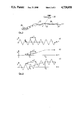
FIG. 3. An additional scheme for an application of the invented method with a screw like path; and
FIG. 4. A length view of the tracking path according to FIG. 3.
FIG. 5. A third possible scheme of an application of the invented method; and
FIG. 6. A magnified example of the inducement of the tracking device into the flight path of the aircraft to be tracked as shown in FIG. 5.
FIG. 1. shows the launching stage 1 of a rocket carrier 2, that includes for example two tracker bodies 3 and 4 and is being shot to point 5. At the time of the take-off the aircraft 6 to be followed is located at point 5. The aircraft has left track 7 behind. Track 7 has at locations I and II a diverse intensity of the path criteria as shown by curves 8 and 9. When rocket carrier 2 passes track 7 at point 5 it releases two tracker bodies 3 and 4, one of which follows the aircraft 6 and the other one flies in the opposite direction to the starting point of the aircraft 6.
As a result it is possible to hit on one side the aircraft 6 and on the other side it's take-off position without need for visual contact between the tracker bodies 3 and 4 and the objects to be hit.
The tracker bodies 3 and 4 carry four steering fins 11, 12, 13 and 14 and each of these four fins carry LIDAR sensors 15, 16, 17 and 18 attached at their exterior sides.
The right side of FIG. 2 shows the intensity criterion 19 as seen in a front veiw of a cut through the path. It has a bell like shape. As a result of the asymetrical position of the tracker bodies 3 respective 4 they receive unequally strong path criteria signals 20, 21. These are being used for repositioning the surfaces 12 and 14.
The turbulent flow of the atmosphere causes the intensity of the path criterion to be unclear. This can be overcome by calculating the average values.
The second example of an application in FIG. 3 shows a helicopter 22 shooting a carrier missile to an enemy missile 24 that is located at takeoff time on position 23. The enemy missile had been fired from an aircraft carrier that can not be seen by the helicopter. The rocket fired from the helicopter 22 releases in position 23 two tracker bodies which follow self-powered along the inside of the path in a screw-like shaped flight path 26 and 27, one follows the missile 24, the other follows in the direction of the aircraft carrier.
FIG. 4 shows how the tracker bodies applied in FIG. 3 can be directed. t stands for time, y is the vertical component of the sensor's flight path. FIG. 4a shows a horizontal view of the screw-like shaped path of a tracker body, as no impact of path criterion on the sensor head. The amplitude of the screw line is A and the time for one complete rotation is ΔT.
FIG. 4b points to a perpendicular plane and projects schematically a unit of the path of the aircraft to be tracked. The path of the aircraft to be followed passes t1 and t2 and is continuously increasing in altitude. The elevation of the aircraft's path during above mentioned rotation time ΔT of the tracking head is Δy.
FIG. 4c points to a perpendicular plane and projects the screw-like shaped path of the tracking head for the same path of the aircraft to be followed as in FIG. 4b. For simplification it is assumed that the change in height Δy is being corrected instantly and without rotations. This assumption however is not realistic and the path of the tracking head is effected by rotations and phases. This does not essentially influence the working principle of the device.
If an object has to be attached it is possible to replace the rocket carrier and its detachable tracking head by a rocket carrier that is simultaneously a tracking head and follows the path.
The method presented is based on the fact that any engine leaves a track in the air. The accuracy of the method is better if the tracks as represented in FIG. 1 and 2 are distinct. Diffusion and turbulence effects make the track to be less concentrated. If the diffusion is bigger, also the disappearance of the track is faster. It is therefore especially advantageous to rely on the reduced mobility of the ions. This method uses the so called Langevin-Ions that are composed of molecular comlexes consisting of hundreds to thousands of molecules. Accordingly they are of very small mobility and as the laws of Brown's molecule mobility show, they have very little diffusion.
As shown in FIG. 5 it is possible to induce the tracking head 1 into track 7 of the aircraft 6 to be followed by a plane connecting the take-off location of the tracking head 3 and two points 30 and 31 of the flight path 32 of the aircraft 6. For example two consecutive points of the aircraft's 6 tracks are being optically or electronically detected. After its take-off the tracking head 3 is being directed to follow a path 33 on a plane defined by points 1, 30 and 31.
After the tracking head 3 has taken off there are three examples for methods according to FIG. 5 to induce tracking head 3 into track 7 of the aircraft 6 to be followed.
The tracking head 3 in the first method is being shot directly on position 31 on a plane defined by points 1, 30 and 31. The aircraft 6 is being located in position 31 at the time of the tracking head's 3 take-off.
The tracking head 3 crosses at position 31 the flight path 32 of the aircraft 6 to be followed. In a normal case the tracking head 3 also crosses the track 7 of the aircraft 6 or at least it vicinity.
When crossing track 7 the tracking head 3 is being directed to a curved path 34 leading to the track 7. This is caused by path criteria detected by the sensor heads or on the basis of calculations of the flight time on a plane defined by 1, 30, 31.
As shown in FIG. 6 the tracking head 3 is being induced into track 7 via a path oscillating around track 7. Each time when track 7 is being crossed the sensors of the tracking device readjust the path of the tracking device 3 according to the new track elements.
In the second method the tracking device 3' is being induced tangentially via a flight path 33' based on plane 1, 30 and 31 into an outside flight path 32 of the aircraft 6 to be followed. Then it is possible to use a screw-like flight path around track 7.
In the third method the tracking device 3" is being induced by approaching on the plane 1, 30 and 31 in a screw-like flight path 35 that is outside of the flight path 32 and therefore also outside of track 7. For this method it is advantageous to explode tracking device 3 by an approach ignitor in range of aircraft 6 to be followed.
Normally the track 7 and the flight path 32 of the aircraft are identical. But strong winds, as demonstrated in FIG. 5 can cause a difference in location between track 7 and flight path 32 of the aircraft 6. This does not have any influence on the invented method.
The tracking head 3 is being directed into one or the opposite track direction by choice, depending on whether aircraft 6 or its take-off point, i.e. an aircraft carrier has to be located and hit.

Claims (13)

I claim:
1. A method of tracking a motor driven flying object by means of a steerable tracker body in which the tracker body is introduced into a trail of a flying object and at least one part of the tracker body is steered in accordance with combustion products generated by a motor of the flying object as a predetermined trail criterion so as to fly along said trail; said combustion products being remotely sensed by at least one lidar sensor incorporated in said tracker body, said lidar being sensitive to combustion generated molecule complexes and combustion generated aerosoles as trail criterion and being connected with a computer generating steering signals in consequency of signals from said lidar sensor.
2. A method according to claim 1 in which at least one part of the tracker body is steered so as to fly within the trail to be followed.
3. A method according to claim 1 in which at least three sensors are used, said sensors being mounted on at least one part of the tracker body at positions spaced at right angles to the flight direction, and in which a gradient of the concentration of the trail criterion is used to provide flight direction control signals for steering said at least one part of the tracker body.
4. A method according to claim 1 in which said at least one part of the tracker body is made to follow a helical flight path having a predetermined revolution time around the axis of the trail of the flying object, and in which the flight path of a part of said tracker body is controlled so that the average flight path coincides at least approximately with the trail axis.
5. A method according to claim 4 in which, in order to control the flight path of said at least one part of the tracker body, an intensity of the trail criterion is detected and compared with an intensity detected during a revolution of the flight path, the result of the comparison being used to provide a signal for controlling the flight path.
6. A method according to claim 5 in which the signal for controlling the flight path is derived from a section of the flight path which corresponds to a plurality of revolutions of the flight path.
7. A method according to claim 1 in which the tracker body is introduced into the trail of the flying object by determining a plane which passes through the take off point of the tracker body and two points on the flight path of the flying object and directing the tracker body along this plane towards the trail of the flying object.
8. A method according to claim 7 in which, after at least one tracker body has entered the trail of the flying object, at least one part of the tracker body is steered in the direction of the trail of the flying object on the basis of trail criteria determined by at least one part of the tracker body.
9. A method according to claim 7 in which the flight path of the flying object is extrapolated with the aid of at least two points along said flight path and the tracker body is guided into the extrapolated flight path of the flying object.
10. A method according to claim 7 in which the flight path of the flying object is extrapolated with the aid of at least two points along said flight path and said at least one part of the tracker body is guided into a substantially helical flight path about the extrapolated flight path of the flying object, such that the mean flight direction of at least one part of the tracker body coincides at least approximately with the extrapolated flight path of the flying object.
11. A method according to claim 10 in which said at least one part of the tracker body is provided with a proximity fuse.
12. A method according to claim 1 or 11 in which at least one part of the tracker body is steered in the opposite direction of the flying object along the trail produced by the flying object.
13. The method of claim 1 in which the tracker body comprises a carrier rocket and at least one motor driven self steerable tracker head.
US06/867,612 1982-08-20 1983-08-12 Method for tracking a motor-operated flying object Expired - Fee Related US4720058A (en)

Applications Claiming Priority (4)

Application Number Priority Date Filing Date Title
CH4974/82A CH658328A5 (en) 1982-08-20 1982-08-20 Tracking system for controlling the tracking of an engine-driven missile
CH4974/82 1982-08-20
CH522182A CH658527A5 (en) 1982-09-02 1982-09-02 Tracking system for controlling the tracking of an engine-driven missile
CH5221/82 1982-09-02

Related Parent Applications (1)

Application Number Title Priority Date Filing Date
US06601366 Continuation-In-Part 1984-04-17

Publications (1)

Publication Number Publication Date
US4720058A true US4720058A (en) 1988-01-19

Family

ID=25696651

Family Applications (1)

Application Number Title Priority Date Filing Date
US06/867,612 Expired - Fee Related US4720058A (en) 1982-08-20 1983-08-12 Method for tracking a motor-operated flying object

Country Status (7)

Country Link
US (1) US4720058A (en)
DE (1) DE3390164D2 (en)
FR (1) FR2532044B1 (en)
GB (1) GB2136931B (en)
IL (1) IL69513A (en)
IT (1) IT1198667B (en)
WO (1) WO1984000806A1 (en)

Cited By (2)

* Cited by examiner, † Cited by third party
Publication number Priority date Publication date Assignee Title
US4970516A (en) * 1984-03-22 1990-11-13 Nicolson Ian M Seagoing vessels
US6066295A (en) * 1996-05-31 2000-05-23 Spectral Sciences, Inc. System and method for remote detection and remediation of airborne and waterborne chemical/biological agents

Families Citing this family (3)

* Cited by examiner, † Cited by third party
Publication number Priority date Publication date Assignee Title
GB9014653D0 (en) * 1989-10-18 1997-11-05 Messerschmitt Boelkow Blohm Auswerfen und verteilen von submunition
SE505189C2 (en) * 1994-11-16 1997-07-14 Bofors Ab Methods and apparatus for combating combat elements along the route of the carrier's vehicle released from a carrier vehicle
IL125455A (en) 1998-07-22 2003-12-10 Rafael Armament Dev Authority System for destroying enemy ballistic missiles

Citations (7)

* Cited by examiner, † Cited by third party
Publication number Priority date Publication date Assignee Title
US2922600A (en) * 1956-04-18 1960-01-26 John B Craft Automatic guidance system
US3219292A (en) * 1961-07-28 1965-11-23 Talbot A Chubb Orientation controller for space vehicles
US3276725A (en) * 1962-09-12 1966-10-04 Boeing Co Navigation system utilizing ion probes
US3900175A (en) * 1972-06-26 1975-08-19 Bofors Ab Guidance system for an anti-aircraft missile
US4170330A (en) * 1974-04-12 1979-10-09 Mathematical Sciences Northwest, Inc. Weapons system
US4193688A (en) * 1970-10-28 1980-03-18 Raytheon Company Optical scanning system
US4383663A (en) * 1976-06-01 1983-05-17 The United States Of America As Represented By The Secretary Of The Navy Active optical terminal homing

Family Cites Families (2)

* Cited by examiner, † Cited by third party
Publication number Priority date Publication date Assignee Title
US3081050A (en) * 1954-04-27 1963-03-12 Bendix Corp Seeker system
FR1191490A (en) * 1958-12-08 1959-10-20 Method for directing a ballistic or guided missile

Patent Citations (7)

* Cited by examiner, † Cited by third party
Publication number Priority date Publication date Assignee Title
US2922600A (en) * 1956-04-18 1960-01-26 John B Craft Automatic guidance system
US3219292A (en) * 1961-07-28 1965-11-23 Talbot A Chubb Orientation controller for space vehicles
US3276725A (en) * 1962-09-12 1966-10-04 Boeing Co Navigation system utilizing ion probes
US4193688A (en) * 1970-10-28 1980-03-18 Raytheon Company Optical scanning system
US3900175A (en) * 1972-06-26 1975-08-19 Bofors Ab Guidance system for an anti-aircraft missile
US4170330A (en) * 1974-04-12 1979-10-09 Mathematical Sciences Northwest, Inc. Weapons system
US4383663A (en) * 1976-06-01 1983-05-17 The United States Of America As Represented By The Secretary Of The Navy Active optical terminal homing

Cited By (2)

* Cited by examiner, † Cited by third party
Publication number Priority date Publication date Assignee Title
US4970516A (en) * 1984-03-22 1990-11-13 Nicolson Ian M Seagoing vessels
US6066295A (en) * 1996-05-31 2000-05-23 Spectral Sciences, Inc. System and method for remote detection and remediation of airborne and waterborne chemical/biological agents

Also Published As

Publication number Publication date
FR2532044A1 (en) 1984-02-24
GB2136931A (en) 1984-09-26
IL69513A (en) 1992-01-15
WO1984000806A1 (en) 1984-03-01
IT1198667B (en) 1988-12-21
DE3390164D2 (en) 1984-10-18
GB8410113D0 (en) 1984-05-31
IT8309500A0 (en) 1983-08-19
GB2136931B (en) 1986-07-30
FR2532044B1 (en) 1989-11-17

Similar Documents

Publication Publication Date Title
Shaw Fighter combat
US4641801A (en) Terminally guided weapon delivery system
JPH0215795B2 (en)
US5439188A (en) Control system
SE8100706L (en) PROCEDURES AND DEVICES IN THE PREPARATION
US5430448A (en) Object detection system
DE102016003238A1 (en) A method of controlling a missile to a flying target
US4720058A (en) Method for tracking a motor-operated flying object
US4625647A (en) Weapon system and missile for the structural destruction of an aerial target by means of a focussed charge
US3169726A (en) Missile guidance system
AU568300B2 (en) Terminally guided weapon delivery system
US5112006A (en) Self defense missile
US20080245256A1 (en) Flying Object for Observing the Ground
US3689741A (en) Bombing instrument for targets having transverse motion relative to aircraft flight path
EP2594891B1 (en) Method for defence against an approaching ballistic rocket and interception system
RU2713546C2 (en) Cruise missile and method of combat use thereof
US4530270A (en) Method of directing a close attack missile to a target
DE3334758A1 (en) Method for combating helicopters with guided missiles
US4993662A (en) Apparatus for guiding a missile
GB2174178A (en) Attacking ground targets
US5301614A (en) Submunition for use during ground-level flight
US5857644A (en) Homing process
US3964694A (en) Aerial acoustic target seeker
DE3337873A1 (en) BULLET FOR GRENADE LAUNCHER SYSTEMS
US2805601A (en) Toss bombing apparatus

Legal Events

Date Code Title Description
AS Assignment

Owner name: GX-HOLDING AG, AESCHENGRABEN 6 CH-4002 BASEL SWITZ

Free format text: ASSIGNMENT OF ASSIGNORS INTEREST.;ASSIGNOR:JAEGER, WALTER;REEL/FRAME:004823/0402

Effective date: 19880104

Owner name: GX-HOLDING AG,SWITZERLAND

Free format text: ASSIGNMENT OF ASSIGNORS INTEREST;ASSIGNOR:JAEGER, WALTER;REEL/FRAME:004823/0402

Effective date: 19880104

REMI Maintenance fee reminder mailed
LAPS Lapse for failure to pay maintenance fees
FP Lapsed due to failure to pay maintenance fee

Effective date: 19920119

STCH Information on status: patent discontinuation

Free format text: PATENT EXPIRED DUE TO NONPAYMENT OF MAINTENANCE FEES UNDER 37 CFR 1.362