US4719677A - Crankcase manufacturing method - Google Patents
Crankcase manufacturing method Download PDFInfo
- Publication number
- US4719677A US4719677A US07/054,283 US5428387A US4719677A US 4719677 A US4719677 A US 4719677A US 5428387 A US5428387 A US 5428387A US 4719677 A US4719677 A US 4719677A
- Authority
- US
- United States
- Prior art keywords
- receiving portions
- bearing caps
- bearing
- journal receiving
- crankcase
- Prior art date
- Legal status (The legal status is an assumption and is not a legal conclusion. Google has not performed a legal analysis and makes no representation as to the accuracy of the status listed.)
- Expired - Fee Related
Links
- 238000004519 manufacturing process Methods 0.000 title claims abstract description 14
- 238000003754 machining Methods 0.000 claims abstract description 14
- 238000005266 casting Methods 0.000 claims description 11
- 238000005553 drilling Methods 0.000 claims description 7
- 238000000034 method Methods 0.000 claims description 7
- 230000013011 mating Effects 0.000 description 3
- 229910001018 Cast iron Inorganic materials 0.000 description 1
- 229910052782 aluminium Inorganic materials 0.000 description 1
- XAGFODPZIPBFFR-UHFFFAOYSA-N aluminium Chemical compound [Al] XAGFODPZIPBFFR-UHFFFAOYSA-N 0.000 description 1
- 238000005219 brazing Methods 0.000 description 1
- 238000002485 combustion reaction Methods 0.000 description 1
- 238000010276 construction Methods 0.000 description 1
- 238000005520 cutting process Methods 0.000 description 1
- 230000006870 function Effects 0.000 description 1
- 239000000463 material Substances 0.000 description 1
- 229910052751 metal Inorganic materials 0.000 description 1
- 239000002184 metal Substances 0.000 description 1
- 238000000926 separation method Methods 0.000 description 1
- 238000003466 welding Methods 0.000 description 1
Images

Classifications
-
- F—MECHANICAL ENGINEERING; LIGHTING; HEATING; WEAPONS; BLASTING
- F02—COMBUSTION ENGINES; HOT-GAS OR COMBUSTION-PRODUCT ENGINE PLANTS
- F02F—CYLINDERS, PISTONS OR CASINGS, FOR COMBUSTION ENGINES; ARRANGEMENTS OF SEALINGS IN COMBUSTION ENGINES
- F02F7/00—Casings, e.g. crankcases
- F02F7/0043—Arrangements of mechanical drive elements
- F02F7/0053—Crankshaft bearings fitted in the crankcase
-
- B—PERFORMING OPERATIONS; TRANSPORTING
- B23—MACHINE TOOLS; METAL-WORKING NOT OTHERWISE PROVIDED FOR
- B23P—METAL-WORKING NOT OTHERWISE PROVIDED FOR; COMBINED OPERATIONS; UNIVERSAL MACHINE TOOLS
- B23P15/00—Making specific metal objects by operations not covered by a single other subclass or a group in this subclass
-
- B—PERFORMING OPERATIONS; TRANSPORTING
- B23—MACHINE TOOLS; METAL-WORKING NOT OTHERWISE PROVIDED FOR
- B23P—METAL-WORKING NOT OTHERWISE PROVIDED FOR; COMBINED OPERATIONS; UNIVERSAL MACHINE TOOLS
- B23P2700/00—Indexing scheme relating to the articles being treated, e.g. manufactured, repaired, assembled, connected or other operations covered in the subgroups
- B23P2700/07—Crankshafts
-
- F—MECHANICAL ENGINEERING; LIGHTING; HEATING; WEAPONS; BLASTING
- F05—INDEXING SCHEMES RELATING TO ENGINES OR PUMPS IN VARIOUS SUBCLASSES OF CLASSES F01-F04
- F05C—INDEXING SCHEME RELATING TO MATERIALS, MATERIAL PROPERTIES OR MATERIAL CHARACTERISTICS FOR MACHINES, ENGINES OR PUMPS OTHER THAN NON-POSITIVE-DISPLACEMENT MACHINES OR ENGINES
- F05C2201/00—Metals
- F05C2201/02—Light metals
- F05C2201/021—Aluminium
-
- F—MECHANICAL ENGINEERING; LIGHTING; HEATING; WEAPONS; BLASTING
- F05—INDEXING SCHEMES RELATING TO ENGINES OR PUMPS IN VARIOUS SUBCLASSES OF CLASSES F01-F04
- F05C—INDEXING SCHEME RELATING TO MATERIALS, MATERIAL PROPERTIES OR MATERIAL CHARACTERISTICS FOR MACHINES, ENGINES OR PUMPS OTHER THAN NON-POSITIVE-DISPLACEMENT MACHINES OR ENGINES
- F05C2201/00—Metals
- F05C2201/04—Heavy metals
- F05C2201/0433—Iron group; Ferrous alloys, e.g. steel
- F05C2201/0436—Iron
-
- Y—GENERAL TAGGING OF NEW TECHNOLOGICAL DEVELOPMENTS; GENERAL TAGGING OF CROSS-SECTIONAL TECHNOLOGIES SPANNING OVER SEVERAL SECTIONS OF THE IPC; TECHNICAL SUBJECTS COVERED BY FORMER USPC CROSS-REFERENCE ART COLLECTIONS [XRACs] AND DIGESTS
- Y10—TECHNICAL SUBJECTS COVERED BY FORMER USPC
- Y10T—TECHNICAL SUBJECTS COVERED BY FORMER US CLASSIFICATION
- Y10T29/00—Metal working
- Y10T29/49—Method of mechanical manufacture
- Y10T29/49229—Prime mover or fluid pump making
- Y10T29/49286—Crankshaft making
-
- Y—GENERAL TAGGING OF NEW TECHNOLOGICAL DEVELOPMENTS; GENERAL TAGGING OF CROSS-SECTIONAL TECHNOLOGIES SPANNING OVER SEVERAL SECTIONS OF THE IPC; TECHNICAL SUBJECTS COVERED BY FORMER USPC CROSS-REFERENCE ART COLLECTIONS [XRACs] AND DIGESTS
- Y10—TECHNICAL SUBJECTS COVERED BY FORMER USPC
- Y10T—TECHNICAL SUBJECTS COVERED BY FORMER US CLASSIFICATION
- Y10T29/00—Metal working
- Y10T29/49—Method of mechanical manufacture
- Y10T29/49789—Obtaining plural product pieces from unitary workpiece
-
- Y—GENERAL TAGGING OF NEW TECHNOLOGICAL DEVELOPMENTS; GENERAL TAGGING OF CROSS-SECTIONAL TECHNOLOGIES SPANNING OVER SEVERAL SECTIONS OF THE IPC; TECHNICAL SUBJECTS COVERED BY FORMER USPC CROSS-REFERENCE ART COLLECTIONS [XRACs] AND DIGESTS
- Y10—TECHNICAL SUBJECTS COVERED BY FORMER USPC
- Y10T—TECHNICAL SUBJECTS COVERED BY FORMER US CLASSIFICATION
- Y10T29/00—Metal working
- Y10T29/49—Method of mechanical manufacture
- Y10T29/49826—Assembling or joining
-
- Y—GENERAL TAGGING OF NEW TECHNOLOGICAL DEVELOPMENTS; GENERAL TAGGING OF CROSS-SECTIONAL TECHNOLOGIES SPANNING OVER SEVERAL SECTIONS OF THE IPC; TECHNICAL SUBJECTS COVERED BY FORMER USPC CROSS-REFERENCE ART COLLECTIONS [XRACs] AND DIGESTS
- Y10—TECHNICAL SUBJECTS COVERED BY FORMER USPC
- Y10T—TECHNICAL SUBJECTS COVERED BY FORMER US CLASSIFICATION
- Y10T74/00—Machine element or mechanism
- Y10T74/21—Elements
- Y10T74/2186—Gear casings
Definitions
- crankcase structures especially of the type wherein crankshaft receiving elements are integrally formed with supporting means at least partially defining a crank chamber.
- the invention pertains particularly to cast crankcase structures for internal combustion engines and the like and especially to engine cylinder blocks incorporating integrally cast crankshaft receiving webs with removable bearing caps.
- an engine cylinder block of cast iron, aluminum or other suitable material, as an integral structure that includes crankcase defining sidewalls interconnected by transverse webs incorporating main journal receiving means for the crankshaft.
- Individual bearing caps, applied to support the crankshaft in the journal receiving means, are commonly formed as separate castings or fabrications. These are machined or otherwise finished separately from the integral cylinder block and crankcase structure, commonly referred to as the engine block. After machining of these separate members, the bearing caps are usually attached to the journal receiving portions of the engine block and the bearing recesses of the block and caps are line bored to provide properly aligned cylindrical bearing openings for receiving the crank journals or main bearing inserts for supporting the journals.
- the present invention provides a novel casting, or otherwise formed integral structure, and a method of manufacture for engine blocks, integral crankcases and the like which substantially reduces the casting and or manufacturing equipment required to provide an unmachined crankcase and the machining steps required for finishing the crankcase or engine block assembly.
- the engine block, or other cylinder block or crankcase structure may be formed as an integral casting, or an otherwise manufactured integral structure, having the usual side walls, webs and recessed journal receiving portions.
- the integral structure further includes bearing caps, preferably formed longitudinally adjacent to and equidistantly unidirectionally spaced from their associated bearing receiving portions to which they are connected by severable connecting means.
- the unitary structure is subsequently machined so as to finish all the exposed surfaces requiring machining, including the joint faces of the bearing caps and bearing receiving portions, the bearing recesses and the attaching holes for securing the bearing caps to the journal receiving portions.
- the severable connecting portions are cut, by sawing or otherwise, so as to separate the bearing caps from their associated journal receiving portions and allow assembly of the separate cap members to the engine block or crankcase journal portions with bolts or other suitable fastening means for final line boring, if required.
- All hole forming operations including drilling reaming and threading of the support holes in the cylinder block journal receiving portions, may be accomplished before separation.
- a gang drill may be utilized to initially drill all the attaching holes in the journal supporting portions of the block and then be indexed by the amount of the offset for drilling the attaching holes in the bearing caps, the same drills being used to form the mating bolt receiving holes of the associated cap and journal receiving portions.
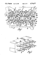
- FIG. 1 is a pictorial view of a partially machined engine cylinder block casting having integrally formed bearing caps in accordance with the invention
- FIG. 2 is a pictorial view of a gang drill for drilling the bearing cap attaching openings in the block and bearing caps of FIG. 1,
- FIG. 3 is a fragmentary pictorial view showing an alternative embodiment of integral journal receiving and bearing cap structure
- FIG. 4 is an exploded pictorial view showing the assembly of a separated bearing cap to its associated journal receiving portion in a crankcase or engine block assembly in accordance with the invention.
- numeral 10 generally indicates an engine block having a single bank 11 of cylinders, not shown, the upper portion of the cylinder bank being omitted from the drawings.
- the lower portion of the block comprises a unitary crankcase 12, preferably cast integrally with the upper cylinder bank portion of the engine block.
- the crankcase portion 12 is adapted to define the upper portion of a complete engine crankcase, the lower portion being enclosed by an oil pan, not shown, subsequently attached to the engine block.
- crankcase 12 there are included a pair of laterally spaced longitudinally extending side walls 14, 15. These are laterally interconnected at spaced intervals intermediate their ends by five transverse bulkheads, walls or webs 16, 18, 19, 20, 22, in which there are respectively provided enlarged laterally extending crankshaft journal receiving portions 23, 24, 26, 27, 28.
- Each of these portions as machined, includes a pair of joint faces 30, a pair of bearing cap attaching openings 31, which are threaded and reamed at their outer edges for hollow dowels, not shown, and a semicylindrical bearing recess 32, the recesses being coaxial with a longitudinal axis, not shown.
- the transverse webs may include depending stiffening gussets 34 and an enlarged boss 35, or the like, for the subsequent provision of an oil drain or dip stick opening as desired.
- bearing caps 36, 38, 39, 40, 42 there are cast integral with the engine block and adjacent to each of the journal receiving portions, bearing caps 36, 38, 39, 40, 42.
- Each of the bearing caps is spaced adjacent and equidistantly longitudinally offset from an associated journal receiving portion and is attached thereto and to the other journal receiving portions and bearing caps by severable connecting portions 43.
- portions 43 are conveniently formed by a runner passage in the mold, not shown, the runner passage having the additional function of transferring molten cast metal to the various bearing cap and journal receiving portions during pouring of the casting.
- these connecting portions 43 are utilized in particular, according to the invention, to support the bearing caps 36, 38, 39, 40, 42 in position adjacent their associated journal receiving portions 23, 24, 26, 27, 28, respectively, for purposes to be subsequently discussed.
- Each of the bearing caps includes a pair of joint faces 44, a pair of attaching openings 46 drilled through the joint faces to the opposite ends of the bearing caps and reamed adjacent the joint faces to receive a hollow dowel, and a bearing recess 47.
- the recesses 47 are substantially semi-cylindrical and are aligned coaxially on the same longitudinal axis as the recesses 32 of the journal receiving portions.
- FIG. 1 represents an integral engine block casting which is fully machined, except for the final step of separating the bearing caps from the remainder of the integral structure for a purpose and in a manner to be subsequently described.
- FIG. 2 there is shown the head portion 48 of a gang drill having ten rotary spindles 50, each containing a drill 51 and all spaced at the center distances of the attaching holes, or openings 31, of the various journal receiving portions.
- crankcase 52 generally indicates a slightly different embodiment of integral crankcase, only a portion of which is shown.
- the crankcase 52 includes parallel side walls 54, 55 interconnected by a plurality of laterally extending webs 56, only one of which is shown.
- Each web 56 includes an enlarged integral crank journal receiving portion 58 having, as machined, joint faces 59, attaching openings 60 and a bearing recess 62, similar in character to those of the embodiment of FIG. 1.
- a bearing cap 64 Adjacent each of the journal receiving portions 58, there is attached by a severable connecting portion 63 a bearing cap 64, which also includes joint faces 66, attaching openings 67 and a bearing recess 68 similar in character to those of the embodiment of FIG. 1.
- FIG. 4 there is shown the crankcase assembly resulting from processing the structure of FIG. 3 to remove the bearing cap 64 from its connection with the journal receiving portion 58 and the assembly of the bearing cap 64 to the journal receiving portion 58 utilizing connecting bolts 70 and hollow dowels 71 to secure and align the assembled elements in their desired positions.
- FIG. 4 also illustrates the lower end 72 of the bearing cap 64, including seats 74 engagable by the bolt heads and which, it should be obvious, may be finished, if desired, in separate machining operations on the bearing cap.
- a preferred method of manufacturing a crankcase assembly, as shown in FIG. 4, or an engine block assembly or the like involves the following steps:
- crankcase or block as shown in FIGS. 3 and 1 after machining, is formed, preferably by casting although other types of fabrication, such as welding, brazing, etc. could be used if desired.
- the as cast, or unmachined, crankcase preferably includes substantially coaxial unfinished or unmachined bearing recesses in the bearing caps and the associated journal receiving portions.
- the engine block or crankcase is then machined, preferably including finish machining of all exposed surfaces, such as the upper deck, the lower edges of the side walls and the joint faces and recesses of the bearing caps and journal receiving portions.
- the attaching openings in the caps and journal receiving portions are also machined at this time.
- the gang drill of FIG. 2 is especially arranged for drilling the attaching openings of the embodiment of FIG. 1. This may be accomplished in sequential drilling steps including first, drilling all the openings in the joint receiving portions. Subsequently, the head portion 48 is indexed a distance equal to the longitudinal offset of the centers of the bearing caps from the centers of their associated journal receiving portions and the mating holes of the associated bearing caps are then drilled in a single pass of the drill head by the same drills which formed the mating openings in the associated journal receiving portions. Similar tooling may be utilized to ream the outer edges of the attaching openings of the journal receiving portions and bearing caps in consecutive passes and to tap threads in the openings of the journal receiving portions if desired.
- the bearing caps are separated from the remainder of the crankcase and their associated journal receiving portions by cutting away, such as by sawing, the connecting portions securing the bearing caps to the remainder of the crankcase. Thereafter, any necessary final finishing, such as machining or spot facing the bearing cap seats 74, may be performed and the caps are assembled to their associated journal receiving portions utilizing appropriate hollow dowels and attaching bolts, such as dowels 71 and bolts 70, respectively.
- bearing recesses of all the attached bearing caps and journal receiving portions are line bored to provide perfectly aligned cylindrical bearing openings which may be intended to receive bearing inserts or to act directly as bearings in appropriate circumstances. If desired, it may be possible to omit the line boring step although it is, at present, considered desirable if not absolutely necessary in order to obtain sufficient accuracy for proper crankshaft bearing support.
Landscapes
- Engineering & Computer Science (AREA)
- Mechanical Engineering (AREA)
- Chemical & Material Sciences (AREA)
- Combustion & Propulsion (AREA)
- General Engineering & Computer Science (AREA)
- Cylinder Crankcases Of Internal Combustion Engines (AREA)
- Shafts, Cranks, Connecting Bars, And Related Bearings (AREA)
Abstract
An improved crankcase structure for engine blocks and the like, may be fabricated wherein the crankcase is initially cast or otherwise formed with bearing caps integral therewith. The caps are preferably secured by severable connecting portions unidirectionally longitudinally adjacent their associated bearing receiving portions in the transverse webs of the cylinder block. The complete crankcase is then machined and the bearing caps are separated for subsequent assembly to the crankcase in conventional fashion. Consequently, the invention reduces the amount of tooling and machining time and equipment required for manufacturing crankcases for engine blocks and the like.
Description
This is a division of U.S. patent application Ser. No. 831,423 filed on Feb. 20, 1986, now U.S. Pat. No. 4,690,112 issued Aug. 1, 1987.
This invention relates to crankcase structures, especially of the type wherein crankshaft receiving elements are integrally formed with supporting means at least partially defining a crank chamber. In preferred embodiments, the invention pertains particularly to cast crankcase structures for internal combustion engines and the like and especially to engine cylinder blocks incorporating integrally cast crankshaft receiving webs with removable bearing caps.
It is known in the art of manufacturing engine cylinder blocks, crankcases and the like to form bearing caps for supporting the engine crankshaft separately from the crankcase supporting structure to which the caps are attached.
For example, it is common to cast an engine cylinder block, of cast iron, aluminum or other suitable material, as an integral structure that includes crankcase defining sidewalls interconnected by transverse webs incorporating main journal receiving means for the crankshaft. Individual bearing caps, applied to support the crankshaft in the journal receiving means, are commonly formed as separate castings or fabrications. These are machined or otherwise finished separately from the integral cylinder block and crankcase structure, commonly referred to as the engine block. After machining of these separate members, the bearing caps are usually attached to the journal receiving portions of the engine block and the bearing recesses of the block and caps are line bored to provide properly aligned cylindrical bearing openings for receiving the crank journals or main bearing inserts for supporting the journals.
This prior method of manufacture requiring plural independently machined components, while generally satisfactory, involves the expense of separate tooling fixtures and machinery for processing the cylinder blocks and bearing caps as well as separate molds or other manufacturing equipment for providing the castings, or otherwise formed separate structures, utilized to manufacture the block assembly with attached bearing caps.
The present invention provides a novel casting, or otherwise formed integral structure, and a method of manufacture for engine blocks, integral crankcases and the like which substantially reduces the casting and or manufacturing equipment required to provide an unmachined crankcase and the machining steps required for finishing the crankcase or engine block assembly.
According to the invention, the engine block, or other cylinder block or crankcase structure, may be formed as an integral casting, or an otherwise manufactured integral structure, having the usual side walls, webs and recessed journal receiving portions. In addition, the integral structure further includes bearing caps, preferably formed longitudinally adjacent to and equidistantly unidirectionally spaced from their associated bearing receiving portions to which they are connected by severable connecting means.
The unitary structure is subsequently machined so as to finish all the exposed surfaces requiring machining, including the joint faces of the bearing caps and bearing receiving portions, the bearing recesses and the attaching holes for securing the bearing caps to the journal receiving portions. Subsequent to, or as part of, the machining operations, the severable connecting portions are cut, by sawing or otherwise, so as to separate the bearing caps from their associated journal receiving portions and allow assembly of the separate cap members to the engine block or crankcase journal portions with bolts or other suitable fastening means for final line boring, if required.
All hole forming operations, including drilling reaming and threading of the support holes in the cylinder block journal receiving portions, may be accomplished before separation. Optionally, a gang drill may be utilized to initially drill all the attaching holes in the journal supporting portions of the block and then be indexed by the amount of the offset for drilling the attaching holes in the bearing caps, the same drills being used to form the mating bolt receiving holes of the associated cap and journal receiving portions.
These and other features and advantages of the invention will be more fully understood from the following description of selected embodiments taken together with the accompanying drawings.
In the drawings:
FIG. 1 is a pictorial view of a partially machined engine cylinder block casting having integrally formed bearing caps in accordance with the invention,
FIG. 2 is a pictorial view of a gang drill for drilling the bearing cap attaching openings in the block and bearing caps of FIG. 1,
FIG. 3 is a fragmentary pictorial view showing an alternative embodiment of integral journal receiving and bearing cap structure, and
FIG. 4 is an exploded pictorial view showing the assembly of a separated bearing cap to its associated journal receiving portion in a crankcase or engine block assembly in accordance with the invention.
In the drawings, numeral 10 generally indicates an engine block having a single bank 11 of cylinders, not shown, the upper portion of the cylinder bank being omitted from the drawings. The lower portion of the block comprises a unitary crankcase 12, preferably cast integrally with the upper cylinder bank portion of the engine block. The crankcase portion 12 is adapted to define the upper portion of a complete engine crankcase, the lower portion being enclosed by an oil pan, not shown, subsequently attached to the engine block.
In the unitary, or integral, crankcase 12, there are included a pair of laterally spaced longitudinally extending side walls 14, 15. These are laterally interconnected at spaced intervals intermediate their ends by five transverse bulkheads, walls or webs 16, 18, 19, 20, 22, in which there are respectively provided enlarged laterally extending crankshaft journal receiving portions 23, 24, 26, 27, 28. Each of these portions, as machined, includes a pair of joint faces 30, a pair of bearing cap attaching openings 31, which are threaded and reamed at their outer edges for hollow dowels, not shown, and a semicylindrical bearing recess 32, the recesses being coaxial with a longitudinal axis, not shown. The transverse webs may include depending stiffening gussets 34 and an enlarged boss 35, or the like, for the subsequent provision of an oil drain or dip stick opening as desired.
In accordance with the invention, there are cast integral with the engine block and adjacent to each of the journal receiving portions, bearing caps 36, 38, 39, 40, 42. Each of the bearing caps is spaced adjacent and equidistantly longitudinally offset from an associated journal receiving portion and is attached thereto and to the other journal receiving portions and bearing caps by severable connecting portions 43. In the illustrated construction, portions 43 are conveniently formed by a runner passage in the mold, not shown, the runner passage having the additional function of transferring molten cast metal to the various bearing cap and journal receiving portions during pouring of the casting. However, these connecting portions 43 are utilized in particular, according to the invention, to support the bearing caps 36, 38, 39, 40, 42 in position adjacent their associated journal receiving portions 23, 24, 26, 27, 28, respectively, for purposes to be subsequently discussed.
Each of the bearing caps, as machined, includes a pair of joint faces 44, a pair of attaching openings 46 drilled through the joint faces to the opposite ends of the bearing caps and reamed adjacent the joint faces to receive a hollow dowel, and a bearing recess 47. The recesses 47 are substantially semi-cylindrical and are aligned coaxially on the same longitudinal axis as the recesses 32 of the journal receiving portions.
As shown, FIG. 1 represents an integral engine block casting which is fully machined, except for the final step of separating the bearing caps from the remainder of the integral structure for a purpose and in a manner to be subsequently described.
Referring now to FIG. 2, there is shown the head portion 48 of a gang drill having ten rotary spindles 50, each containing a drill 51 and all spaced at the center distances of the attaching holes, or openings 31, of the various journal receiving portions.
Referring now to FIG. 3, numeral 52 generally indicates a slightly different embodiment of integral crankcase, only a portion of which is shown. The crankcase 52 includes parallel side walls 54, 55 interconnected by a plurality of laterally extending webs 56, only one of which is shown. Each web 56 includes an enlarged integral crank journal receiving portion 58 having, as machined, joint faces 59, attaching openings 60 and a bearing recess 62, similar in character to those of the embodiment of FIG. 1.
Adjacent each of the journal receiving portions 58, there is attached by a severable connecting portion 63 a bearing cap 64, which also includes joint faces 66, attaching openings 67 and a bearing recess 68 similar in character to those of the embodiment of FIG. 1.
In FIG. 4, there is shown the crankcase assembly resulting from processing the structure of FIG. 3 to remove the bearing cap 64 from its connection with the journal receiving portion 58 and the assembly of the bearing cap 64 to the journal receiving portion 58 utilizing connecting bolts 70 and hollow dowels 71 to secure and align the assembled elements in their desired positions. FIG. 4 also illustrates the lower end 72 of the bearing cap 64, including seats 74 engagable by the bolt heads and which, it should be obvious, may be finished, if desired, in separate machining operations on the bearing cap.
A preferred method of manufacturing a crankcase assembly, as shown in FIG. 4, or an engine block assembly or the like involves the following steps:
1. An integral crankcase or block, as shown in FIGS. 3 and 1 after machining, is formed, preferably by casting although other types of fabrication, such as welding, brazing, etc. could be used if desired. The as cast, or unmachined, crankcase preferably includes substantially coaxial unfinished or unmachined bearing recesses in the bearing caps and the associated journal receiving portions.
2. The engine block or crankcase is then machined, preferably including finish machining of all exposed surfaces, such as the upper deck, the lower edges of the side walls and the joint faces and recesses of the bearing caps and journal receiving portions. The attaching openings in the caps and journal receiving portions are also machined at this time.
The gang drill of FIG. 2 is especially arranged for drilling the attaching openings of the embodiment of FIG. 1. This may be accomplished in sequential drilling steps including first, drilling all the openings in the joint receiving portions. Subsequently, the head portion 48 is indexed a distance equal to the longitudinal offset of the centers of the bearing caps from the centers of their associated journal receiving portions and the mating holes of the associated bearing caps are then drilled in a single pass of the drill head by the same drills which formed the mating openings in the associated journal receiving portions. Similar tooling may be utilized to ream the outer edges of the attaching openings of the journal receiving portions and bearing caps in consecutive passes and to tap threads in the openings of the journal receiving portions if desired.
3. After the block or crankcase is completely machined, and possibly as part of the same machining process, the bearing caps are separated from the remainder of the crankcase and their associated journal receiving portions by cutting away, such as by sawing, the connecting portions securing the bearing caps to the remainder of the crankcase. Thereafter, any necessary final finishing, such as machining or spot facing the bearing cap seats 74, may be performed and the caps are assembled to their associated journal receiving portions utilizing appropriate hollow dowels and attaching bolts, such as dowels 71 and bolts 70, respectively.
4. Finally, the bearing recesses of all the attached bearing caps and journal receiving portions are line bored to provide perfectly aligned cylindrical bearing openings which may be intended to receive bearing inserts or to act directly as bearings in appropriate circumstances. If desired, it may be possible to omit the line boring step although it is, at present, considered desirable if not absolutely necessary in order to obtain sufficient accuracy for proper crankshaft bearing support.
While it is presently considered most desirable that the mounting of the bearing caps, as cast with the integral crankcase, should be such as to be offset longitudinally an amount equidistant from their respective associated journal receiving portions, it should be apparent that other arrangements for casting the bearing caps together with the crankcase might also be utilized and advantageous. Thus, two bearing caps might be located between two adjacent journal receiving members or a full set of bearing caps might be located between two adjacent webs or at one end of the cylinder block. These variations, while not presently considered to be the best manner of carrying out the invention, are nevertheless considered to be within the scope of the structures and methods contemplated in the present invention.
While the invention has been described by reference to certain embodiments chosen for purposes of illustration, it should be understood that numerous changes could be made without departing from the spirit and scope of the inventive concepts disclosed. Accordingly, it is intended that the invention not be limited to the disclosed methods and embodiments, but that it be given the full scope permitted by the language of the following claims.
Claims (3)
1. A method of manufacturing a crankcase assembly, said method including the steps of
forming an integral crankcase having a plurality of longitudinally spaced laterally extending journal receiving portions and longitudinally displaced bearing caps connected with at least one of said journal receiving portions by severable connecting portions, said journal receiving portions and bearing caps including unfinished bearing recesses substantially longitudinally coaxially aligned,
machining said crankcase including the journal receiving portions and bearing caps to provide attaching holes, finished joint face surfaces and machined bearing recesses,
separating the bearing caps from the crankcase by severing the connecting portions, and
securing the severed bearing caps to associated journal receiving portions with suitable attaching means.
2. A method of manufacturing an engine block assembly, said method including the steps of
casting an integral engine block including a crankcase portion having a plurality of longitudinally spaced laterally extending journal receiving portions and longitudinally displaced bearing caps connected with at least one of said journal receiving portions by severable connecting portions, said journal receiving portions and bearing caps including unfinished bearing recesses substantially longitudinally coaxially aligned,
machining said block including the journal receiving portions and bearing caps to provide attaching holes, finished joint face surfaces and machined bearing recesses,
separating the bearing caps from the crankcase portion by severing the connecting portions, and
securing the severed bearing caps to associated journal receiving portions with suitable attaching means.
3. A method as in claim 2 wherein, prior to machining, said bearing caps are all displaced equidistantly in the same direction from their respective associated journal receiving portions and said machining step includes gang drilling all the attaching holes in the journal receiving portions and all the attaching holes in their associated bearing caps in two successive steps using the same gang drill to form matched pairs of journal receiving portions and associated bearing caps.
Priority Applications (1)
| Application Number | Priority Date | Filing Date | Title |
|---|---|---|---|
| US07/054,283 US4719677A (en) | 1986-02-20 | 1987-05-26 | Crankcase manufacturing method |
Applications Claiming Priority (2)
| Application Number | Priority Date | Filing Date | Title |
|---|---|---|---|
| US06/831,423 US4690112A (en) | 1986-02-20 | 1986-02-20 | Crankcase structure |
| US07/054,283 US4719677A (en) | 1986-02-20 | 1987-05-26 | Crankcase manufacturing method |
Related Parent Applications (1)
| Application Number | Title | Priority Date | Filing Date |
|---|---|---|---|
| US06/831,423 Division US4690112A (en) | 1986-02-20 | 1986-02-20 | Crankcase structure |
Publications (1)
| Publication Number | Publication Date |
|---|---|
| US4719677A true US4719677A (en) | 1988-01-19 |
Family
ID=26732829
Family Applications (1)
| Application Number | Title | Priority Date | Filing Date |
|---|---|---|---|
| US07/054,283 Expired - Fee Related US4719677A (en) | 1986-02-20 | 1987-05-26 | Crankcase manufacturing method |
Country Status (1)
| Country | Link |
|---|---|
| US (1) | US4719677A (en) |
Cited By (8)
| Publication number | Priority date | Publication date | Assignee | Title |
|---|---|---|---|---|
| US5635305A (en) * | 1995-05-22 | 1997-06-03 | Itt Automotive, Inc. | Machinable cast-in-place tube enclosure fittings |
| EP0953779A3 (en) * | 1998-04-29 | 2000-01-05 | Bayerische Motoren Werke Aktiengesellschaft, Patentabteilung AJ-3 | Method of making a split bearing arrangement in a casted engine housing, particularly sliding bearing for alternating piston engines |
| US20050092128A1 (en) * | 2003-10-31 | 2005-05-05 | Leo Wenstrup | Bolted pilot web with precision machined bearing stop |
| US20100011574A1 (en) * | 2008-07-16 | 2010-01-21 | Gm Global Technology Operations, Inc. | Engine and method for improved crankcase fatigue strength with fracture-split main bearing caps |
| CN101745822B (en) * | 2009-12-15 | 2011-11-30 | 中国北车集团大连机车车辆有限公司 | Anti-deformation process for processing diesel engine crankcase |
| US20120093665A1 (en) * | 2009-05-28 | 2012-04-19 | Flanigan Paul J | Light Weight Crankcase Casting for Compressor |
| CN104476129A (en) * | 2014-11-21 | 2015-04-01 | 广东鸿图南通压铸有限公司 | Processing method for oil sump single body of turbosupercharged engine |
| CN110666466A (en) * | 2019-11-18 | 2020-01-10 | 杭州锴铭机械制造有限公司 | High-precision machining process of crankcase |
Citations (4)
| Publication number | Priority date | Publication date | Assignee | Title |
|---|---|---|---|---|
| US1433821A (en) * | 1919-09-18 | 1922-10-31 | Clarence E Hull | Crank case for internal-combustion engines |
| US1560342A (en) * | 1922-01-20 | 1925-11-03 | William J Foster | Sheet-steel crank case |
| US2098451A (en) * | 1936-07-18 | 1937-11-09 | Gilmore Harry | Method of strengthening crankcases |
| US4674455A (en) * | 1981-01-27 | 1987-06-23 | Honda Giken Kogyo Kabushiki Kaisha | Split crankcase for V-type engine |
-
1987
- 1987-05-26 US US07/054,283 patent/US4719677A/en not_active Expired - Fee Related
Patent Citations (4)
| Publication number | Priority date | Publication date | Assignee | Title |
|---|---|---|---|---|
| US1433821A (en) * | 1919-09-18 | 1922-10-31 | Clarence E Hull | Crank case for internal-combustion engines |
| US1560342A (en) * | 1922-01-20 | 1925-11-03 | William J Foster | Sheet-steel crank case |
| US2098451A (en) * | 1936-07-18 | 1937-11-09 | Gilmore Harry | Method of strengthening crankcases |
| US4674455A (en) * | 1981-01-27 | 1987-06-23 | Honda Giken Kogyo Kabushiki Kaisha | Split crankcase for V-type engine |
Cited By (14)
| Publication number | Priority date | Publication date | Assignee | Title |
|---|---|---|---|---|
| US5635305A (en) * | 1995-05-22 | 1997-06-03 | Itt Automotive, Inc. | Machinable cast-in-place tube enclosure fittings |
| US5899233A (en) * | 1995-05-22 | 1999-05-04 | Itt Automotive, Inc. | Machinable cast-in-place tube enclosure fittings |
| EP0953779A3 (en) * | 1998-04-29 | 2000-01-05 | Bayerische Motoren Werke Aktiengesellschaft, Patentabteilung AJ-3 | Method of making a split bearing arrangement in a casted engine housing, particularly sliding bearing for alternating piston engines |
| US20050092128A1 (en) * | 2003-10-31 | 2005-05-05 | Leo Wenstrup | Bolted pilot web with precision machined bearing stop |
| US7152502B2 (en) * | 2003-10-31 | 2006-12-26 | Dana Corporation | Bolted pilot web with precision machined bearing stop |
| CN100482980C (en) * | 2003-10-31 | 2009-04-29 | 德纳重型车辆系统集团有限责任公司 | Bolted pilot web with precision machined bearing stop |
| US20100011574A1 (en) * | 2008-07-16 | 2010-01-21 | Gm Global Technology Operations, Inc. | Engine and method for improved crankcase fatigue strength with fracture-split main bearing caps |
| US8181344B2 (en) * | 2008-07-16 | 2012-05-22 | GM Global Technology Operations LLC | Engine and method for improved crankcase fatigue strength with fracture-split main bearing caps |
| US8573177B2 (en) | 2008-07-16 | 2013-11-05 | GM Global Technology Operations LLC | Engine and method for improved crankcase fatigue strength with fracture-split main bearing caps |
| US20120093665A1 (en) * | 2009-05-28 | 2012-04-19 | Flanigan Paul J | Light Weight Crankcase Casting for Compressor |
| CN101745822B (en) * | 2009-12-15 | 2011-11-30 | 中国北车集团大连机车车辆有限公司 | Anti-deformation process for processing diesel engine crankcase |
| CN104476129A (en) * | 2014-11-21 | 2015-04-01 | 广东鸿图南通压铸有限公司 | Processing method for oil sump single body of turbosupercharged engine |
| CN104476129B (en) * | 2014-11-21 | 2016-09-07 | 广东鸿图南通压铸有限公司 | The processing method of turbocharged engine oil sump monomer |
| CN110666466A (en) * | 2019-11-18 | 2020-01-10 | 杭州锴铭机械制造有限公司 | High-precision machining process of crankcase |
Similar Documents
| Publication | Publication Date | Title |
|---|---|---|
| DE3010635C2 (en) | ||
| EP0439459B1 (en) | A method of producing a crown for an articulated piston | |
| US4010718A (en) | Reciprocating piston engines having piston oil cooling | |
| EP1843029B1 (en) | Composite cylinder case | |
| KR100400066B1 (en) | Connecting rods for piston-operated machines such as compressors and methods for manufacturing the same | |
| US4719677A (en) | Crankcase manufacturing method | |
| US2681054A (en) | Construction of die-cast cylinder blocks | |
| US4690112A (en) | Crankcase structure | |
| US2703263A (en) | Connecting rod | |
| CN109630537B (en) | Method for machining oval core in crankshaft | |
| US20050015982A1 (en) | Method for producing a connecting rod for a reciprocating-piston engine | |
| US5224804A (en) | Tooling system and method for broaching engine components | |
| EP0771944B1 (en) | Crank case for an internal combustion piston engine | |
| US4033016A (en) | Crankshaft welded together from individual elements, and method of making same | |
| EP2292373A2 (en) | Crankcase and main bearing cap construction | |
| US2740393A (en) | Cylinder block and method of construction | |
| JP3339330B2 (en) | Cylinder block for internal combustion engine | |
| DE602004001249T2 (en) | Method for producing a bearing part | |
| DE3121408C2 (en) | Liquid-cooled multi-cylinder internal combustion engine | |
| US3320940A (en) | Engine cylinder block | |
| US4711203A (en) | Timing case for a cylinder head of internal combustion engines having gas changing valves arranged essentially in parallel to one another | |
| GB2172691A (en) | Cast crankshafts | |
| GB2187817A (en) | Crankshafts | |
| US2318474A (en) | Radial connecting rod | |
| CN209908624U (en) | Integrated full-cast aluminum main bearing cover |
Legal Events
| Date | Code | Title | Description |
|---|---|---|---|
| FPAY | Fee payment |
Year of fee payment: 4 |
|
| REMI | Maintenance fee reminder mailed | ||
| LAPS | Lapse for failure to pay maintenance fees | ||
| FP | Lapsed due to failure to pay maintenance fee |
Effective date: 19960121 |
|
| STCH | Information on status: patent discontinuation |
Free format text: PATENT EXPIRED DUE TO NONPAYMENT OF MAINTENANCE FEES UNDER 37 CFR 1.362 |