US4010718A - Reciprocating piston engines having piston oil cooling - Google Patents
Reciprocating piston engines having piston oil cooling Download PDFInfo
- Publication number
- US4010718A US4010718A US05/544,530 US54453075A US4010718A US 4010718 A US4010718 A US 4010718A US 54453075 A US54453075 A US 54453075A US 4010718 A US4010718 A US 4010718A
- Authority
- US
- United States
- Prior art keywords
- jet
- assembly
- piston
- engine
- crankcase
- Prior art date
- Legal status (The legal status is an assumption and is not a legal conclusion. Google has not performed a legal analysis and makes no representation as to the accuracy of the status listed.)
- Expired - Lifetime
Links
- 238000001816 cooling Methods 0.000 title claims abstract description 11
- 239000003921 oil Substances 0.000 claims description 22
- 239000010687 lubricating oil Substances 0.000 claims description 6
- 230000000712 assembly Effects 0.000 claims description 5
- 238000000429 assembly Methods 0.000 claims description 5
- 238000002485 combustion reaction Methods 0.000 claims description 3
- 238000005192 partition Methods 0.000 claims description 3
- 238000005553 drilling Methods 0.000 description 3
- 230000000295 complement effect Effects 0.000 description 2
- 241001125877 Gobio gobio Species 0.000 description 1
- 230000009286 beneficial effect Effects 0.000 description 1
- 238000003780 insertion Methods 0.000 description 1
- 230000037431 insertion Effects 0.000 description 1
- 238000004519 manufacturing process Methods 0.000 description 1
- 239000002184 metal Substances 0.000 description 1
- 238000000034 method Methods 0.000 description 1
- 230000003014 reinforcing effect Effects 0.000 description 1
Images


Classifications
-
- F—MECHANICAL ENGINEERING; LIGHTING; HEATING; WEAPONS; BLASTING
- F01—MACHINES OR ENGINES IN GENERAL; ENGINE PLANTS IN GENERAL; STEAM ENGINES
- F01M—LUBRICATING OF MACHINES OR ENGINES IN GENERAL; LUBRICATING INTERNAL COMBUSTION ENGINES; CRANKCASE VENTILATING
- F01M1/00—Pressure lubrication
- F01M1/08—Lubricating systems characterised by the provision therein of lubricant jetting means
-
- F—MECHANICAL ENGINEERING; LIGHTING; HEATING; WEAPONS; BLASTING
- F01—MACHINES OR ENGINES IN GENERAL; ENGINE PLANTS IN GENERAL; STEAM ENGINES
- F01P—COOLING OF MACHINES OR ENGINES IN GENERAL; COOLING OF INTERNAL-COMBUSTION ENGINES
- F01P3/00—Liquid cooling
- F01P3/06—Arrangements for cooling pistons
- F01P3/08—Cooling of piston exterior only, e.g. by jets
-
- F—MECHANICAL ENGINEERING; LIGHTING; HEATING; WEAPONS; BLASTING
- F01—MACHINES OR ENGINES IN GENERAL; ENGINE PLANTS IN GENERAL; STEAM ENGINES
- F01M—LUBRICATING OF MACHINES OR ENGINES IN GENERAL; LUBRICATING INTERNAL COMBUSTION ENGINES; CRANKCASE VENTILATING
- F01M1/00—Pressure lubrication
- F01M1/08—Lubricating systems characterised by the provision therein of lubricant jetting means
- F01M2001/086—Lubricating systems characterised by the provision therein of lubricant jetting means for lubricating gudgeon pins
-
- F—MECHANICAL ENGINEERING; LIGHTING; HEATING; WEAPONS; BLASTING
- F02—COMBUSTION ENGINES; HOT-GAS OR COMBUSTION-PRODUCT ENGINE PLANTS
- F02B—INTERNAL-COMBUSTION PISTON ENGINES; COMBUSTION ENGINES IN GENERAL
- F02B3/00—Engines characterised by air compression and subsequent fuel addition
- F02B3/06—Engines characterised by air compression and subsequent fuel addition with compression ignition
Definitions
- the present invention relates to cooling of reciprocating engine pistons by streams of oil produced by jets.
- the present invention has the object of overcoming this drawback.
- a reciprocating piston engine comprises a cylinder block having a cylinder therein, a piston reciprocable in the cylinder, a crankcase, a crank rotatable on a bearing in the crankcase, a connecting rod connecting the crank to the piston, a lubricating oil passage in said crankcase, a bore formed in said crankcase between the bearing and said piston and meeting said oil passage, a tubular jet assembly accurately located and held in position in said bore in said block, having a hollow interior connected to said oil passage and a jet passage accurately formed and positioned prior to assembly in said bore.
- a method of making a piston cooling system comprises the steps of forming a tubular assembly having a hollow interior, forming a locating surface on the assembly, forming a feed passage and a jet passage in a wall of the assembly and orientated in a particular direction with respect to said assembly, forming a bore in a wall of the crankcase closely adjacent to a cylinder and transverse thereto so that the bore and a lubricating oil feed passage intersects, locating and fastening said assembly in said bore in a precise position relative to said cylinder with the aid of said locating surface and a locating tool.
- the tubular assembly includes two jet passages and the assembly protrudes from both sides of a through bore in a crankcase partition to enable the respective jet passages to be presented to two adjacent cylinders.
- the assembly is an interface fit in said bore.
- the jet passage is so orientated as to project a stream of oil at the part of the underside of the piston crown which is axially aligned with the combustion chamber.
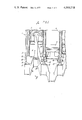
- FIG. 1 is a schematic cross section on the center line of a reciprocating piston engine cylinder block and crankcase, two cylinders only being shown.
- FIG. 2 is a cross section on section II -- II end elevation with the piston removed.
- FIG. 3 is a partially cut away elevation from below viewed in the direction of arrow III in FIG. 2.
- FIG. 4 is subdivided into FIGS. 4a, 4b, 4c and 4d and shows the oil jet assembly in left end, side, right end, and lower elevations respectively.
- FIGS. 5a and 5b are views of special tools used for positioning and fixing the oil jet assembly in the engine block or crankcase from the left.
- FIGS. 1, 2 and 3 there is shown an engine 1 having a cylinder block 2, which in this case is integral with a crankcase 3.
- Cylinder block 2 accommodates cylinders 4.
- the cylinder head and sump and other parts have been omitted from these figures for the sake of simplicity, it being understood that the invention applies to the operation of the engine as a whole but not to the omitted parts.
- Pistons 5 are slidable in the cylinders 4 and are supported by connecting rods 6 themselves pivotted on crank pin bearings 7 in the crankshaft 8.
- the crankshaft 8 is carried on main bearings 9 in the crankcase 3.
- the main bearings 9 are located one at each end of the crankcase 3 and one in between each cylinder 4.
- the end walls 10 of the crankcase 3 carry the end main bearings 9 and main bearing supports 11 carry the intermediate main bearings 9.
- FIG. 2 also shows a main lubricating oil gallery 16.
- a drilled passage 17 interconnects the gallery 16 with the hole 12.
- FIGS. 4a - 4d A jet assembly 18 is shown in FIGS. 4a - 4d.
- This consists of a cylinder 19 of metal formed with tapered end portions 20 and 21 and a center cylindrical portion 22.
- the center portion 22 is such that it is an interference fit in hole 12.
- the end portion 20 has a flat 25 machined thereon.
- the cylinder 19 may be formed from stock tube or may simply be bored out, see FIGS. 4a, 4b and 4c, by a central bore 27 which is closed by a ball bearing 28 pressed into place.
- a side drilling 29 intersects the central bore 27.
- Oil jet holes or jet passages 30 and 31 are formed by placing the jet assembly in a suitable jig and drilling an appropriate size of small hole.
- the jig is so arranged as to hold the assembly 18 in such a position that the desired angles ⁇ x ⁇ seen in FIG. 4a and ⁇ y ⁇ seen in FIG. 4b are achieved in the tapered end portion 20.
- the flat 25 on this portion is important in locating the assembly in the jig.
- the angles ⁇ w ⁇ and ⁇ z ⁇ seen in FIGS. 4c and 4b respectively might be different to ⁇ x ⁇ and ⁇ y ⁇ and a different jig would be used to form hole 31 though the size of the two holes 30 and 31 would probably be the same.
- the oil jet assembly 18 is then inserted into tool 23.
- a complementary flat 32 to flat 25 on the interior of the tool 23 ensures that the assembly 18 and tool 23 are in proper relationship.
- An alignment guage 33 which can be of the form shown in FIGS. 5a and 5b ensures that the assembly is inserted into hole 12 in its proper angular relation as seen in FIG. 2.
- the alignment gauge 33 consists of a tab 34 welded to the tool 23 and carrying a semicylindrical shell 35 which is complementary to the bearing 9.
- Axial pressure applied to the tool 23 drives the assembly into an interference fit in hole 12 to its proper axial position which occurs when the front surface 36 of the tool abuts the wall 11.
- jet holes 30 and 31 are in proper position to direct oil accurately to a desired area on the underside of the piston 5. Also the side drilling 29 is in alignment with connecting oil passage 17.
- a tool is similar to that shown in FIG. 5 may be used for fitting the assembly in the hole 12 from the other side of the wall 11. It may be necessary to enlarge the hole 12 in the end wall to permit insertion of a tool and assembly from outside the engine. Alternatively various other forms of alignment gauge can be used.
- FIG. 3 The need for accuracy in directing the jet of cooling oil to a particular point on the underside of a piston is illustrated in FIG. 3 by reference to the right hand cylinder only, where in a diesel engine having an antechamber 40 in the cylinder head the emergence of a stream of hot gas impinges on the crown of the piston 5 at a point 41 before dispersing.
- This point on the piston crown gets extremely hot and a stream 39 of lubricating oil precisely directed at an opposite point on the underside of the crown is very beneficial in terms of preserving the reliability of the piston.
- the stream 39 may be directed at an opening leading to a cooling gallery in the piston.
- Each piston can receive two cooling jets one from each of the jet assemblies protruding into the corresponding cylinder, though it may be convenient for each of the end cylinders to have only one assembly protruding into it.
- more than one pair of jet holes may be formed in the jet assembly so that two or more oil streams are directed at different parts of one piston from one jet assembly.
- the alignment gauge 33 suggested herein is exemplary of a number of such gauges which may be preferred.
- the invention enables jet assemblies to be made accurately before fitting and enables the jets to avoid the gudgeon pin bosses 42 or other parts of the piston which might otherwise interfere. Further, it enables oil jet assemblies to be incorporated where oil jet cooling might not be possible by conventional means. An example of where it would be extremely difficult to provide oil jet cooling by conventional means is the case of the engine with an integral cylinder head and cylinder block. Moreover the invention enables numerous tests to be carried out on one engine simply by substituting oil jet assemblies. The invention also offers the advantage of enabling a common jet assembly to be used for all of a range of engines, the only distinction being the choice of angles ⁇ w ⁇ , ⁇ x ⁇ , ⁇ y ⁇ , ⁇ z ⁇ or the size of the jet passage or the number of jet passages.
Landscapes
- Engineering & Computer Science (AREA)
- Mechanical Engineering (AREA)
- General Engineering & Computer Science (AREA)
- Chemical & Material Sciences (AREA)
- Combustion & Propulsion (AREA)
- Lubrication Of Internal Combustion Engines (AREA)
- Cylinder Crankcases Of Internal Combustion Engines (AREA)
Abstract
A reciprocating piston engine in which oil cooling is provided by a hollow oil jet assembly located accurately by a location tool and pressed into position in a bore in the crankcase of the engine. Accurately drilled and aligned jet passages are formed in the assembly which is then fitted into position with good accuracy to enable accurate direction of a jet or jets of cooling oil to a desired point or points on the underside of a piston.
Description
The present invention relates to cooling of reciprocating engine pistons by streams of oil produced by jets.
It is known to cool the pistons of internal combustion reciprocating engines by directing a stream of lubricating oil at them during the operation of the engine. It is also known to direct a stream of oil into a passage in the piston which leads to a gallery therein.
Hitherto, it has been difficult to direct the stream accurately without resorting to expensive methods of controlling the alignment of the jet.
The present invention has the object of overcoming this drawback.
According to the present invention a reciprocating piston engine comprises a cylinder block having a cylinder therein, a piston reciprocable in the cylinder, a crankcase, a crank rotatable on a bearing in the crankcase, a connecting rod connecting the crank to the piston, a lubricating oil passage in said crankcase, a bore formed in said crankcase between the bearing and said piston and meeting said oil passage, a tubular jet assembly accurately located and held in position in said bore in said block, having a hollow interior connected to said oil passage and a jet passage accurately formed and positioned prior to assembly in said bore.
For a reciprocating engine having a cylinder block, crankcase and reciprocating piston, a method of making a piston cooling system comprises the steps of forming a tubular assembly having a hollow interior, forming a locating surface on the assembly, forming a feed passage and a jet passage in a wall of the assembly and orientated in a particular direction with respect to said assembly, forming a bore in a wall of the crankcase closely adjacent to a cylinder and transverse thereto so that the bore and a lubricating oil feed passage intersects, locating and fastening said assembly in said bore in a precise position relative to said cylinder with the aid of said locating surface and a locating tool.
Preferably the tubular assembly includes two jet passages and the assembly protrudes from both sides of a through bore in a crankcase partition to enable the respective jet passages to be presented to two adjacent cylinders.
Preferably also the assembly is an interface fit in said bore.
Preferably and in the case of a diesel engine the jet passage is so orientated as to project a stream of oil at the part of the underside of the piston crown which is axially aligned with the combustion chamber.
The preferred embodiment of the invention will now be described with reference to the accompanying drawings of which:
FIG. 1 is a schematic cross section on the center line of a reciprocating piston engine cylinder block and crankcase, two cylinders only being shown.
FIG. 2 is a cross section on section II -- II end elevation with the piston removed.
FIG. 3 is a partially cut away elevation from below viewed in the direction of arrow III in FIG. 2.
FIG. 4 is subdivided into FIGS. 4a, 4b, 4c and 4d and shows the oil jet assembly in left end, side, right end, and lower elevations respectively.
FIGS. 5a and 5b are views of special tools used for positioning and fixing the oil jet assembly in the engine block or crankcase from the left.
In FIGS. 1, 2 and 3 there is shown an engine 1 having a cylinder block 2, which in this case is integral with a crankcase 3. Cylinder block 2 accommodates cylinders 4. The cylinder head and sump and other parts have been omitted from these figures for the sake of simplicity, it being understood that the invention applies to the operation of the engine as a whole but not to the omitted parts. Pistons 5 are slidable in the cylinders 4 and are supported by connecting rods 6 themselves pivotted on crank pin bearings 7 in the crankshaft 8. The crankshaft 8 is carried on main bearings 9 in the crankcase 3.
The main bearings 9 are located one at each end of the crankcase 3 and one in between each cylinder 4. The end walls 10 of the crankcase 3 carry the end main bearings 9 and main bearing supports 11 carry the intermediate main bearings 9.
Referring now to FIG. 1, the end walls 10 and bearing supports 11 are bored to form accurately and aligned holes 12. Referring to FIG. 2 it will be seen that reinforcing ribs 13 are formed on wall 11 and one of these 13a is closely adjacent one hole 12.
FIG. 2 also shows a main lubricating oil gallery 16. A drilled passage 17 interconnects the gallery 16 with the hole 12.
A jet assembly 18 is shown in FIGS. 4a - 4d. This consists of a cylinder 19 of metal formed with tapered end portions 20 and 21 and a center cylindrical portion 22. The center portion 22 is such that it is an interference fit in hole 12. The end portion 20 has a flat 25 machined thereon. The cylinder 19 may be formed from stock tube or may simply be bored out, see FIGS. 4a, 4b and 4c, by a central bore 27 which is closed by a ball bearing 28 pressed into place. A side drilling 29 intersects the central bore 27.
Oil jet holes or jet passages 30 and 31 are formed by placing the jet assembly in a suitable jig and drilling an appropriate size of small hole. The jig is so arranged as to hold the assembly 18 in such a position that the desired angles `x` seen in FIG. 4a and `y` seen in FIG. 4b are achieved in the tapered end portion 20. The flat 25 on this portion is important in locating the assembly in the jig. The angles `w` and `z` seen in FIGS. 4c and 4b respectively might be different to `x` and `y` and a different jig would be used to form hole 31 though the size of the two holes 30 and 31 would probably be the same.
The oil jet assembly 18 is then inserted into tool 23. A complementary flat 32 to flat 25 on the interior of the tool 23 ensures that the assembly 18 and tool 23 are in proper relationship. An alignment guage 33 which can be of the form shown in FIGS. 5a and 5b ensures that the assembly is inserted into hole 12 in its proper angular relation as seen in FIG. 2. The alignment gauge 33 consists of a tab 34 welded to the tool 23 and carrying a semicylindrical shell 35 which is complementary to the bearing 9. Thus the assembly 18 held in fixed relationship to the tool 23 is offered up to the hole 12 in its desired and proper position. Axial pressure applied to the tool 23 drives the assembly into an interference fit in hole 12 to its proper axial position which occurs when the front surface 36 of the tool abuts the wall 11.
After proper assembly the jet holes 30 and 31 are in proper position to direct oil accurately to a desired area on the underside of the piston 5. Also the side drilling 29 is in alignment with connecting oil passage 17.
A tool is similar to that shown in FIG. 5 may be used for fitting the assembly in the hole 12 from the other side of the wall 11. It may be necessary to enlarge the hole 12 in the end wall to permit insertion of a tool and assembly from outside the engine. Alternatively various other forms of alignment gauge can be used.
The need for accuracy in directing the jet of cooling oil to a particular point on the underside of a piston is illustrated in FIG. 3 by reference to the right hand cylinder only, where in a diesel engine having an antechamber 40 in the cylinder head the emergence of a stream of hot gas impinges on the crown of the piston 5 at a point 41 before dispersing. This point on the piston crown gets extremely hot and a stream 39 of lubricating oil precisely directed at an opposite point on the underside of the crown is very beneficial in terms of preserving the reliability of the piston. Alternatively, the stream 39 may be directed at an opening leading to a cooling gallery in the piston.
Each piston can receive two cooling jets one from each of the jet assemblies protruding into the corresponding cylinder, though it may be convenient for each of the end cylinders to have only one assembly protruding into it. As a further alternative, more than one pair of jet holes may be formed in the jet assembly so that two or more oil streams are directed at different parts of one piston from one jet assembly.
The alignment gauge 33 suggested herein is exemplary of a number of such gauges which may be preferred.
The invention enables jet assemblies to be made accurately before fitting and enables the jets to avoid the gudgeon pin bosses 42 or other parts of the piston which might otherwise interfere. Further, it enables oil jet assemblies to be incorporated where oil jet cooling might not be possible by conventional means. An example of where it would be extremely difficult to provide oil jet cooling by conventional means is the case of the engine with an integral cylinder head and cylinder block. Moreover the invention enables numerous tests to be carried out on one engine simply by substituting oil jet assemblies. The invention also offers the advantage of enabling a common jet assembly to be used for all of a range of engines, the only distinction being the choice of angles `w`, `x`, `y`, `z` or the size of the jet passage or the number of jet passages.
Claims (6)
1. A reciprocating piston engine comprising a cylinder block having a cylinder therein, a piston reciprocable in the cylinder, a crankcase, a crank rotatable on a bearing in the crankcase, a connecting rod connecting the crank to the piston, a lubricating oil passage in said crankcase, a bore formed in said crankcase between the bearing and said cylinder and meeting said oil passage, a tubular jet assembly, locating means on said jet assembly for accurately positioning said jet assembly within the engine and said jet assembly having an interference fit with said bore to retain said jet assembly's position in said bore in said crankcase, said jet assembly having a hollow interior connected to said oil passage and a jet passage accurately formed and positioned prior to assembly in said bore.
2. An engine as claimed in claim 1 wherein said tubular assembly includes two jet passages and the assembly protrudes from both sides of a through bore in a crankcase partition to enable each jet passage to be presented to one of adjacent cylinders separated by said partition.
3. An engine as claimed in claim 2 wherein at least two jet assemblies provide cooling oil for every piston.
4. An engine as claimed in claim 3 wherein each jet assembly is provided with at least three jet passages, oil from at least two of said passages being directed at one piston.
5. An engine as claimed in claim 1 and particularly in the case of a diesel engine, wherein said jet passage is so orientated as to project a stream of oil at the part of the underside of the piston which is axially aligned with the combustion chamber.
6. An engine as claimed in claim 1 wherein said jet assembly is in an interconnecting wall connecting the crank bearing to the cylinder.
Applications Claiming Priority (2)
| Application Number | Priority Date | Filing Date | Title |
|---|---|---|---|
| GB537474A GB1475181A (en) | 1974-02-06 | 1974-02-06 | Reciprocating engine having piston oil cooling |
| UK5374/74 | 1974-02-06 |
Publications (1)
| Publication Number | Publication Date |
|---|---|
| US4010718A true US4010718A (en) | 1977-03-08 |
Family
ID=9794933
Family Applications (1)
| Application Number | Title | Priority Date | Filing Date |
|---|---|---|---|
| US05/544,530 Expired - Lifetime US4010718A (en) | 1974-02-06 | 1975-01-27 | Reciprocating piston engines having piston oil cooling |
Country Status (6)
| Country | Link |
|---|---|
| US (1) | US4010718A (en) |
| DE (1) | DE2505019A1 (en) |
| ES (1) | ES434482A1 (en) |
| FR (1) | FR2259981B1 (en) |
| GB (1) | GB1475181A (en) |
| PL (1) | PL105241B1 (en) |
Cited By (27)
| Publication number | Priority date | Publication date | Assignee | Title |
|---|---|---|---|---|
| US4114571A (en) * | 1975-10-16 | 1978-09-19 | Max Ruf | Means for controlling the oil cooling of the piston of a piston engine |
| US4204487A (en) * | 1977-04-28 | 1980-05-27 | David Brown Tractors Limited | Internal combustion engines |
| US4206726A (en) * | 1977-07-18 | 1980-06-10 | Caterpillar Tractor Co. | Double orifice piston cooling nozzle for reciprocating engines |
| US4508065A (en) * | 1983-03-21 | 1985-04-02 | General Motors Corporation | Piston cooling oil delivery tube assembly |
| DE4012475A1 (en) * | 1989-04-28 | 1990-10-31 | Volkswagen Ag | PISTON COOLING FOR AN INTERNAL COMBUSTION ENGINE |
| US5533472A (en) * | 1995-07-31 | 1996-07-09 | Chrysler Corporation | Oil jet nozzle for an internal combustion with reciprocating pistons |
| DE19634742A1 (en) * | 1996-08-28 | 1998-03-05 | Deutz Ag | Internal combustion engine with piston lubricating and cooling oil injector |
| US6019071A (en) * | 1998-09-22 | 2000-02-01 | Chrysler Corporation | Engine windage tray |
| US6250275B1 (en) | 1999-08-16 | 2001-06-26 | Caterpillar Inc. | Internal combustion engine piston pin lubrication |
| EP1156198A3 (en) * | 2000-05-17 | 2003-02-19 | Man Nutzfahrzeuge Ag | Piston cooling for an internal combustion engine |
| EP1288460A1 (en) * | 2001-08-31 | 2003-03-05 | Honda Giken Kogyo Kabushiki Kaisha | Piston cooling device for multicylinder engine |
| EP1676989A1 (en) | 2005-01-03 | 2006-07-05 | Ford Global Technologies, LLC, A subsidary of Ford Motor Company | Internal combustion engine with a piston cooling device |
| US20070039572A1 (en) * | 2004-06-10 | 2007-02-22 | Achates Power, Llc | Two-stroke, opposed-piston internal combustion engine |
| US20080035101A1 (en) * | 2004-04-22 | 2008-02-14 | Wacker Construction Equipment Ag | Oil Supply For An Internal Combustion Engine |
| EP2133533A1 (en) * | 2008-06-12 | 2009-12-16 | Aichi Machine Industry Co. Ltd. | Piston cooling structure |
| US20100212637A1 (en) * | 2009-02-20 | 2010-08-26 | Achates Power, Inc. | Cylinder and piston assemblies for opposed piston engines |
| US20100212613A1 (en) * | 2009-02-20 | 2010-08-26 | Achates Power, Inc. | Multi-Cylinder opposed piston engines |
| US20100212638A1 (en) * | 2009-02-20 | 2010-08-26 | Achates Power, Inc. | Opposed piston engines with controlled provision of lubricant for lubrication and cooling |
| CN103498734A (en) * | 2013-09-26 | 2014-01-08 | 浙江吉利控股集团有限公司 | Main bearing base of cylinder block and cooling system of cylinder block |
| US8875668B2 (en) | 2012-08-31 | 2014-11-04 | Honda Motor Co., Ltd. | Apparatus configured to shelter oil-jet device from inadvertent installation damage |
| US8973484B2 (en) | 2011-07-01 | 2015-03-10 | Mahle Industries Inc. | Piston with cooling gallery |
| US9163505B2 (en) | 2010-08-16 | 2015-10-20 | Achates Power, Inc. | Piston constructions for opposed-piston engines |
| US9470136B2 (en) | 2014-03-06 | 2016-10-18 | Achates Power, Inc. | Piston cooling configurations utilizing lubricating oil from a bearing reservoir in an opposed-piston engine |
| US9850801B2 (en) * | 2015-08-28 | 2017-12-26 | Kawasaki Jukogyo Kabushiki Kaisha | Piston cooling structure in combustion engine |
| US9856820B2 (en) | 2010-10-05 | 2018-01-02 | Mahle International Gmbh | Piston assembly |
| WO2020253174A1 (en) * | 2019-06-21 | 2020-12-24 | 北京致行慕远科技有限公司 | All-terrain vehicle and engine thereof |
| US20230243315A1 (en) * | 2023-03-17 | 2023-08-03 | Michael J. Holihan | Method to mitigate reverse oil flow to the combustion chamber via hybrid cylinder cutout for internal combustion engines |
Families Citing this family (6)
| Publication number | Priority date | Publication date | Assignee | Title |
|---|---|---|---|---|
| DE3703047C1 (en) * | 1987-02-03 | 1988-06-23 | Mtu Friedrichshafen Gmbh | Lube oil channel |
| FR2743847B1 (en) * | 1996-01-18 | 1998-02-27 | Bontaz Centre | SOCKET COOLING JET |
| DE19633167A1 (en) * | 1996-08-17 | 1998-02-19 | Porsche Ag | Spray nozzle for the piston cooling of an internal combustion engine |
| US5881684A (en) * | 1997-07-21 | 1999-03-16 | Bontaz Centre, Societe Anonyme | Interference fit cooling spray nozzle |
| RU2166648C2 (en) * | 1997-12-24 | 2001-05-10 | Акционерное общество открытого типа - Холдинговая компания "Барнаултрансмаш" | Internal combustion engine |
| WO2006030256A1 (en) * | 2004-09-15 | 2006-03-23 | Ford Otomativ Sanayi Anonim Sirketi | An engine comprising an improved oil jet device |
Citations (6)
| Publication number | Priority date | Publication date | Assignee | Title |
|---|---|---|---|---|
| US1680883A (en) * | 1926-12-13 | 1928-08-14 | Leonard V Hosford | Internal-combustion engine |
| US2569103A (en) * | 1949-04-08 | 1951-09-25 | & De Participations Eau Gaz El | Internal-combustion engine piston |
| US2966146A (en) * | 1957-10-29 | 1960-12-27 | Schweitzer And Hussmann | Air-cooled, port-scavenged engine |
| US2967516A (en) * | 1958-09-02 | 1961-01-10 | Stumpfig Friedrich | Two cycle internal combustion engine with means for fuel evaporation |
| US3182642A (en) * | 1961-10-20 | 1965-05-11 | Otto V Drtina | Internal combustion engine with enforced double-loop scavenging and overall cooling |
| US3221718A (en) * | 1964-01-09 | 1965-12-07 | Continental Aviat & Eng Corp | Piston construction |
Family Cites Families (1)
| Publication number | Priority date | Publication date | Assignee | Title |
|---|---|---|---|---|
| DE1956121A1 (en) * | 1969-11-07 | 1971-05-27 | Kloeckner Humboldt Deutz Ag | Piston cooling for reciprocating internal combustion engines with spray nozzles that can be switched off |
-
1974
- 1974-02-06 GB GB537474A patent/GB1475181A/en not_active Expired
-
1975
- 1975-01-27 US US05/544,530 patent/US4010718A/en not_active Expired - Lifetime
- 1975-01-30 FR FR7502885A patent/FR2259981B1/fr not_active Expired
- 1975-02-04 PL PL1975177799A patent/PL105241B1/en unknown
- 1975-02-05 ES ES434482A patent/ES434482A1/en not_active Expired
- 1975-02-06 DE DE19752505019 patent/DE2505019A1/en not_active Ceased
Patent Citations (6)
| Publication number | Priority date | Publication date | Assignee | Title |
|---|---|---|---|---|
| US1680883A (en) * | 1926-12-13 | 1928-08-14 | Leonard V Hosford | Internal-combustion engine |
| US2569103A (en) * | 1949-04-08 | 1951-09-25 | & De Participations Eau Gaz El | Internal-combustion engine piston |
| US2966146A (en) * | 1957-10-29 | 1960-12-27 | Schweitzer And Hussmann | Air-cooled, port-scavenged engine |
| US2967516A (en) * | 1958-09-02 | 1961-01-10 | Stumpfig Friedrich | Two cycle internal combustion engine with means for fuel evaporation |
| US3182642A (en) * | 1961-10-20 | 1965-05-11 | Otto V Drtina | Internal combustion engine with enforced double-loop scavenging and overall cooling |
| US3221718A (en) * | 1964-01-09 | 1965-12-07 | Continental Aviat & Eng Corp | Piston construction |
Cited By (49)
| Publication number | Priority date | Publication date | Assignee | Title |
|---|---|---|---|---|
| US4114571A (en) * | 1975-10-16 | 1978-09-19 | Max Ruf | Means for controlling the oil cooling of the piston of a piston engine |
| US4204487A (en) * | 1977-04-28 | 1980-05-27 | David Brown Tractors Limited | Internal combustion engines |
| US4206726A (en) * | 1977-07-18 | 1980-06-10 | Caterpillar Tractor Co. | Double orifice piston cooling nozzle for reciprocating engines |
| US4508065A (en) * | 1983-03-21 | 1985-04-02 | General Motors Corporation | Piston cooling oil delivery tube assembly |
| DE4012475A1 (en) * | 1989-04-28 | 1990-10-31 | Volkswagen Ag | PISTON COOLING FOR AN INTERNAL COMBUSTION ENGINE |
| US5533472A (en) * | 1995-07-31 | 1996-07-09 | Chrysler Corporation | Oil jet nozzle for an internal combustion with reciprocating pistons |
| DE19634742A1 (en) * | 1996-08-28 | 1998-03-05 | Deutz Ag | Internal combustion engine with piston lubricating and cooling oil injector |
| US6019071A (en) * | 1998-09-22 | 2000-02-01 | Chrysler Corporation | Engine windage tray |
| US6250275B1 (en) | 1999-08-16 | 2001-06-26 | Caterpillar Inc. | Internal combustion engine piston pin lubrication |
| US6532912B2 (en) * | 2000-05-17 | 2003-03-18 | Man Nutzfahrzeuge Ag | Piston cooling system for an internal combustion engine |
| EP1156198A3 (en) * | 2000-05-17 | 2003-02-19 | Man Nutzfahrzeuge Ag | Piston cooling for an internal combustion engine |
| EP1288460A1 (en) * | 2001-08-31 | 2003-03-05 | Honda Giken Kogyo Kabushiki Kaisha | Piston cooling device for multicylinder engine |
| US6739291B2 (en) | 2001-08-31 | 2004-05-25 | Honda Giken Kogyo Kabushiki Kaisha | Piston cooling device for multicylinder engine |
| US20080035101A1 (en) * | 2004-04-22 | 2008-02-14 | Wacker Construction Equipment Ag | Oil Supply For An Internal Combustion Engine |
| US7753024B2 (en) * | 2004-04-22 | 2010-07-13 | Wacker Neuson Se | Oil supply for an internal combustion engine |
| US20080314688A1 (en) * | 2004-06-10 | 2008-12-25 | Achates Power, Inc. | Internal combustion engine with provision for lubricating pistons |
| US7861679B2 (en) | 2004-06-10 | 2011-01-04 | Achates Power, Inc. | Cylinder and piston assemblies for opposed piston engines |
| US7784436B2 (en) | 2004-06-10 | 2010-08-31 | Achates Power, Inc. | Two-cycle, opposed-piston internal combustion engine |
| US20080163848A1 (en) * | 2004-06-10 | 2008-07-10 | Achates Power, Inc. | Opposed piston engine with piston compliance |
| US20070039572A1 (en) * | 2004-06-10 | 2007-02-22 | Achates Power, Llc | Two-stroke, opposed-piston internal combustion engine |
| US7546819B2 (en) | 2004-06-10 | 2009-06-16 | Achates Power. | Two-stroke, opposed-piston internal combustion engine |
| US7549401B2 (en) | 2004-06-10 | 2009-06-23 | Achates Power, Inc. | Two-cycle, opposed-piston internal combustion engine |
| US7591235B2 (en) | 2004-06-10 | 2009-09-22 | Achates Power, Inc. | Opposed piston engine with piston compliance |
| US20090293820A1 (en) * | 2004-06-10 | 2009-12-03 | Achates Power, Inc. | Two-cycle, opposed-piston internal combustion engine |
| US20070245892A1 (en) * | 2004-06-10 | 2007-10-25 | Achates Power, Llc | Two-Cycle, Opposed-Piston Internal Combustion Engine |
| US20100012055A1 (en) * | 2004-06-10 | 2010-01-21 | Achates Power, Inc. | Cylinder and piston assemblies for opposed piston engines |
| US8087389B2 (en) | 2004-06-10 | 2012-01-03 | Achates Power, Inc. | Two-cycle, opposed-piston internal combustion engine |
| US20100186723A1 (en) * | 2004-06-10 | 2010-07-29 | Achates Power, Llc | Two-cycle, opposed-piston internal combustion engine |
| US8286596B2 (en) | 2004-06-10 | 2012-10-16 | Achates Power, Inc. | Two-cycle, opposed-piston internal combustion engine |
| US8281755B2 (en) | 2004-06-10 | 2012-10-09 | Achates Power, Inc. | Internal combustion engine with provision for lubricating pistons |
| EP1676989A1 (en) | 2005-01-03 | 2006-07-05 | Ford Global Technologies, LLC, A subsidary of Ford Motor Company | Internal combustion engine with a piston cooling device |
| US7201118B2 (en) | 2005-01-03 | 2007-04-10 | Ford Global Technologies, Llc | Piston-cooling arrangement for an internal combustion engine |
| EP2133533A1 (en) * | 2008-06-12 | 2009-12-16 | Aichi Machine Industry Co. Ltd. | Piston cooling structure |
| US20100212638A1 (en) * | 2009-02-20 | 2010-08-26 | Achates Power, Inc. | Opposed piston engines with controlled provision of lubricant for lubrication and cooling |
| US20100212613A1 (en) * | 2009-02-20 | 2010-08-26 | Achates Power, Inc. | Multi-Cylinder opposed piston engines |
| US20100212637A1 (en) * | 2009-02-20 | 2010-08-26 | Achates Power, Inc. | Cylinder and piston assemblies for opposed piston engines |
| US8539918B2 (en) | 2009-02-20 | 2013-09-24 | Achates Power, Inc. | Multi-cylinder opposed piston engines |
| US8550041B2 (en) | 2009-02-20 | 2013-10-08 | Achates Power, Inc. | Cylinder and piston assemblies for opposed piston engines |
| US9328692B2 (en) | 2009-02-20 | 2016-05-03 | Achates Power, Inc. | Opposed piston engines with controlled provision of lubricant for lubrication and cooling |
| US9163505B2 (en) | 2010-08-16 | 2015-10-20 | Achates Power, Inc. | Piston constructions for opposed-piston engines |
| US9856820B2 (en) | 2010-10-05 | 2018-01-02 | Mahle International Gmbh | Piston assembly |
| US8973484B2 (en) | 2011-07-01 | 2015-03-10 | Mahle Industries Inc. | Piston with cooling gallery |
| US8875668B2 (en) | 2012-08-31 | 2014-11-04 | Honda Motor Co., Ltd. | Apparatus configured to shelter oil-jet device from inadvertent installation damage |
| CN103498734A (en) * | 2013-09-26 | 2014-01-08 | 浙江吉利控股集团有限公司 | Main bearing base of cylinder block and cooling system of cylinder block |
| US9470136B2 (en) | 2014-03-06 | 2016-10-18 | Achates Power, Inc. | Piston cooling configurations utilizing lubricating oil from a bearing reservoir in an opposed-piston engine |
| US10208704B2 (en) | 2014-03-06 | 2019-02-19 | Achates Power, Inc. | Piston cooling configurations utilizing lubricating oil from a bearing reservoir in an opposed-piston engine |
| US9850801B2 (en) * | 2015-08-28 | 2017-12-26 | Kawasaki Jukogyo Kabushiki Kaisha | Piston cooling structure in combustion engine |
| WO2020253174A1 (en) * | 2019-06-21 | 2020-12-24 | 北京致行慕远科技有限公司 | All-terrain vehicle and engine thereof |
| US20230243315A1 (en) * | 2023-03-17 | 2023-08-03 | Michael J. Holihan | Method to mitigate reverse oil flow to the combustion chamber via hybrid cylinder cutout for internal combustion engines |
Also Published As
| Publication number | Publication date |
|---|---|
| PL105241B1 (en) | 1979-09-29 |
| FR2259981A1 (en) | 1975-08-29 |
| DE2505019A1 (en) | 1975-08-07 |
| GB1475181A (en) | 1977-06-01 |
| FR2259981B1 (en) | 1978-02-24 |
| ES434482A1 (en) | 1977-03-16 |
Similar Documents
| Publication | Publication Date | Title |
|---|---|---|
| US4010718A (en) | Reciprocating piston engines having piston oil cooling | |
| US4343270A (en) | Internal combustion engine | |
| US4622864A (en) | Modular crank subassembly and built-up crankshaft therefor | |
| US5881684A (en) | Interference fit cooling spray nozzle | |
| FI79888B (en) | OLJEKYLD, FLERDELAD PLUNGERKOLV FOER SLAGKOLVSFOERBRAENNINGSMOTOR. | |
| US4993378A (en) | Lubricating oil passage structure for a cylinder block | |
| US20110120299A1 (en) | Cast piston with pin bore lubrication and method of manufacturing same | |
| US8484826B2 (en) | Apparatus and method for installing connecting rods | |
| US6298810B1 (en) | Mounting a cooling nozzle on an engine block | |
| US6027784A (en) | Connecting rod | |
| US7063049B2 (en) | Directed spray jet and installation tool | |
| FI70453B (en) | KOLVBULT OCH KOLV SAERSKILT FOER EN FOERBRAENNINGSMOTOR MED ENOLV UTRUSTAD MED EN DYLIK BULT | |
| US4719677A (en) | Crankcase manufacturing method | |
| JP2002021558A (en) | Piston cooling system for internal combustion engines | |
| US4690112A (en) | Crankcase structure | |
| CN101501314A (en) | Engine cast component having witness marks and method of machining same | |
| KR100191613B1 (en) | Fixing jig of starting connecting rod | |
| GB2187817A (en) | Crankshafts | |
| US20040211314A1 (en) | Method of manufacturing a piston, tooling for implementing the method, and a piston obtained thereby | |
| JP2005163557A (en) | Engine cylinder block structure and oil passage leakage inspection method | |
| JPS6030488Y2 (en) | Connecting rods for internal combustion engines | |
| JP2589045Y2 (en) | Engine oil jet piston cooling system | |
| JPH11303872A (en) | Bearing structure with oil groove | |
| JPH08232624A (en) | Lubricating structure between piston and connecting rod in internal combustion engine | |
| JPH0238090Y2 (en) |