US4718737A - Power braking system with reduced pedal travel - Google Patents
Power braking system with reduced pedal travel Download PDFInfo
- Publication number
- US4718737A US4718737A US06/899,857 US89985786A US4718737A US 4718737 A US4718737 A US 4718737A US 89985786 A US89985786 A US 89985786A US 4718737 A US4718737 A US 4718737A
- Authority
- US
- United States
- Prior art keywords
- response
- valve
- braking
- brake
- valves
- Prior art date
- Legal status (The legal status is an assumption and is not a legal conclusion. Google has not performed a legal analysis and makes no representation as to the accuracy of the status listed.)
- Expired - Fee Related
Links
Images
Classifications
-
- B—PERFORMING OPERATIONS; TRANSPORTING
- B60—VEHICLES IN GENERAL
- B60T—VEHICLE BRAKE CONTROL SYSTEMS OR PARTS THEREOF; BRAKE CONTROL SYSTEMS OR PARTS THEREOF, IN GENERAL; ARRANGEMENT OF BRAKING ELEMENTS ON VEHICLES IN GENERAL; PORTABLE DEVICES FOR PREVENTING UNWANTED MOVEMENT OF VEHICLES; VEHICLE MODIFICATIONS TO FACILITATE COOLING OF BRAKES
- B60T8/00—Arrangements for adjusting wheel-braking force to meet varying vehicular or ground-surface conditions, e.g. limiting or varying distribution of braking force
- B60T8/32—Arrangements for adjusting wheel-braking force to meet varying vehicular or ground-surface conditions, e.g. limiting or varying distribution of braking force responsive to a speed condition, e.g. acceleration or deceleration
- B60T8/34—Arrangements for adjusting wheel-braking force to meet varying vehicular or ground-surface conditions, e.g. limiting or varying distribution of braking force responsive to a speed condition, e.g. acceleration or deceleration having a fluid pressure regulator responsive to a speed condition
- B60T8/44—Arrangements for adjusting wheel-braking force to meet varying vehicular or ground-surface conditions, e.g. limiting or varying distribution of braking force responsive to a speed condition, e.g. acceleration or deceleration having a fluid pressure regulator responsive to a speed condition co-operating with a power-assist booster means associated with a master cylinder for controlling the release and reapplication of brake pressure through an interaction with the power assist device, i.e. open systems
- B60T8/441—Arrangements for adjusting wheel-braking force to meet varying vehicular or ground-surface conditions, e.g. limiting or varying distribution of braking force responsive to a speed condition, e.g. acceleration or deceleration having a fluid pressure regulator responsive to a speed condition co-operating with a power-assist booster means associated with a master cylinder for controlling the release and reapplication of brake pressure through an interaction with the power assist device, i.e. open systems using hydraulic boosters
-
- B—PERFORMING OPERATIONS; TRANSPORTING
- B60—VEHICLES IN GENERAL
- B60T—VEHICLE BRAKE CONTROL SYSTEMS OR PARTS THEREOF; BRAKE CONTROL SYSTEMS OR PARTS THEREOF, IN GENERAL; ARRANGEMENT OF BRAKING ELEMENTS ON VEHICLES IN GENERAL; PORTABLE DEVICES FOR PREVENTING UNWANTED MOVEMENT OF VEHICLES; VEHICLE MODIFICATIONS TO FACILITATE COOLING OF BRAKES
- B60T8/00—Arrangements for adjusting wheel-braking force to meet varying vehicular or ground-surface conditions, e.g. limiting or varying distribution of braking force
- B60T8/17—Using electrical or electronic regulation means to control braking
- B60T8/176—Brake regulation specially adapted to prevent excessive wheel slip during vehicle deceleration, e.g. ABS
- B60T8/1761—Brake regulation specially adapted to prevent excessive wheel slip during vehicle deceleration, e.g. ABS responsive to wheel or brake dynamics, e.g. wheel slip, wheel acceleration or rate of change of brake fluid pressure
- B60T8/17616—Microprocessor-based systems
-
- B—PERFORMING OPERATIONS; TRANSPORTING
- B60—VEHICLES IN GENERAL
- B60T—VEHICLE BRAKE CONTROL SYSTEMS OR PARTS THEREOF; BRAKE CONTROL SYSTEMS OR PARTS THEREOF, IN GENERAL; ARRANGEMENT OF BRAKING ELEMENTS ON VEHICLES IN GENERAL; PORTABLE DEVICES FOR PREVENTING UNWANTED MOVEMENT OF VEHICLES; VEHICLE MODIFICATIONS TO FACILITATE COOLING OF BRAKES
- B60T8/00—Arrangements for adjusting wheel-braking force to meet varying vehicular or ground-surface conditions, e.g. limiting or varying distribution of braking force
- B60T8/32—Arrangements for adjusting wheel-braking force to meet varying vehicular or ground-surface conditions, e.g. limiting or varying distribution of braking force responsive to a speed condition, e.g. acceleration or deceleration
- B60T8/321—Arrangements for adjusting wheel-braking force to meet varying vehicular or ground-surface conditions, e.g. limiting or varying distribution of braking force responsive to a speed condition, e.g. acceleration or deceleration deceleration
- B60T8/3255—Systems in which the braking action is dependent on brake pedal data
- B60T8/326—Hydraulic systems
- B60T8/3265—Hydraulic systems with control of the booster
-
- B—PERFORMING OPERATIONS; TRANSPORTING
- B60—VEHICLES IN GENERAL
- B60T—VEHICLE BRAKE CONTROL SYSTEMS OR PARTS THEREOF; BRAKE CONTROL SYSTEMS OR PARTS THEREOF, IN GENERAL; ARRANGEMENT OF BRAKING ELEMENTS ON VEHICLES IN GENERAL; PORTABLE DEVICES FOR PREVENTING UNWANTED MOVEMENT OF VEHICLES; VEHICLE MODIFICATIONS TO FACILITATE COOLING OF BRAKES
- B60T8/00—Arrangements for adjusting wheel-braking force to meet varying vehicular or ground-surface conditions, e.g. limiting or varying distribution of braking force
- B60T8/32—Arrangements for adjusting wheel-braking force to meet varying vehicular or ground-surface conditions, e.g. limiting or varying distribution of braking force responsive to a speed condition, e.g. acceleration or deceleration
- B60T8/34—Arrangements for adjusting wheel-braking force to meet varying vehicular or ground-surface conditions, e.g. limiting or varying distribution of braking force responsive to a speed condition, e.g. acceleration or deceleration having a fluid pressure regulator responsive to a speed condition
- B60T8/343—Systems characterised by their lay-out
- B60T8/344—Hydraulic systems
- B60T8/347—3 Channel systems
-
- B—PERFORMING OPERATIONS; TRANSPORTING
- B60—VEHICLES IN GENERAL
- B60T—VEHICLE BRAKE CONTROL SYSTEMS OR PARTS THEREOF; BRAKE CONTROL SYSTEMS OR PARTS THEREOF, IN GENERAL; ARRANGEMENT OF BRAKING ELEMENTS ON VEHICLES IN GENERAL; PORTABLE DEVICES FOR PREVENTING UNWANTED MOVEMENT OF VEHICLES; VEHICLE MODIFICATIONS TO FACILITATE COOLING OF BRAKES
- B60T8/00—Arrangements for adjusting wheel-braking force to meet varying vehicular or ground-surface conditions, e.g. limiting or varying distribution of braking force
- B60T8/32—Arrangements for adjusting wheel-braking force to meet varying vehicular or ground-surface conditions, e.g. limiting or varying distribution of braking force responsive to a speed condition, e.g. acceleration or deceleration
- B60T8/34—Arrangements for adjusting wheel-braking force to meet varying vehicular or ground-surface conditions, e.g. limiting or varying distribution of braking force responsive to a speed condition, e.g. acceleration or deceleration having a fluid pressure regulator responsive to a speed condition
- B60T8/44—Arrangements for adjusting wheel-braking force to meet varying vehicular or ground-surface conditions, e.g. limiting or varying distribution of braking force responsive to a speed condition, e.g. acceleration or deceleration having a fluid pressure regulator responsive to a speed condition co-operating with a power-assist booster means associated with a master cylinder for controlling the release and reapplication of brake pressure through an interaction with the power assist device, i.e. open systems
- B60T8/445—Arrangements for adjusting wheel-braking force to meet varying vehicular or ground-surface conditions, e.g. limiting or varying distribution of braking force responsive to a speed condition, e.g. acceleration or deceleration having a fluid pressure regulator responsive to a speed condition co-operating with a power-assist booster means associated with a master cylinder for controlling the release and reapplication of brake pressure through an interaction with the power assist device, i.e. open systems replenishing the released brake fluid volume into the brake piping
Definitions
- the present invention relates to devices for reducing the pedal travel required to apply the brakes in a powered braking system and in particular to a device which utilizes a hydraulic booster and modulating valves associated with an antilock braking system to reduce the pedal travel required during normal braking.
- the brakes of a vehicle are primarily a pressure responsive device in contrast to, for example, an accelerator which is a motion responsive device.
- Various mechanical characteristics of a braking system such as volume and movement of wheel cylinders required to bring the brake shoes into contact with a drum or rotor, expansion of flexible brake lines and movement between the open and closed positions of the piston of a master cylinder relative to a fill orifice, inherently cause some amount of pedal movement before braking pressure builds. This characteristic will be further increased in dual or split braking systems.
- experience has shown that drivers prefer to have some degree of movement of the brake pedal during use so that the brakes will exhibit a desirable degree of "feel".
- various devices have been proposed to provide a means to produce a braking system that does not exhibit excessive pedal movement and which simultaneously provides a desired degree of feel.
- anti-lock or adaptive braking systems have now been developed, such systems incorporating sensors, a computing circuit, and a plurality of modulating valves for automatically controlling the application of braking pressure in response to an incipient skid condition of a vehicle's wheels.
- Such systems typically incorporate a power booster in the form of a motor driven pump and an accumulator to provide power boost during normal braking operation and to provide a source of pressurized fluid during adaptive braking operation.
- the present invention utilizes existing adaptive braking hardward including the pump-accumulator, brake switch, hydraulic booster, and modulating valves in cooperation with the adaptive braking control to provide a braking system having reduced brake pedal travel during normal non-adaptive braking operation.
- actuation of the conventional brake switch provides an input signal to the adaptive braking control.
- the control in response to the signal, actuates the isolation valves of one of the hydraulic circuits of the adaptive braking system and the build valves of that hydraulic circuit to connect same to the hydraulic booster.
- the hydraulic circuit thus actuated, operates as a full power hydraulic circuit.
- Another object of the invention is to provide such a system which utilizes existing anti-lock braking system hardware to reduce brake pedal travel during normal braking operation.
- Still another object of the invention is to provide such a system which utilizes a brake switch in conjunction with anti-lock braking components to provide a system exhibiting reduced brake pedal travel.
- Another object of the invention is to provide a braking system in which the pump, accumulator, hydraulic booster, isolation and build valves, and electronic control unit of an anti-lock braking system are utilized to operate at least one hydraulic circuit of the braking system as a full power braking system during normal braking operation.
- Still another object of the invention is to provide such a system in which the pedal feel can be controlled by adjustment of a standard brake switch.
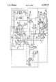
- the braking system includes a dual piston displacement-type master cylinder 10 having a primary and a secondary hydraulic cylinder 12, 14, respectively, actuated by pressurized fluid in a booster cylinder 16.
- the booster cylinder receives pressurized fluid the pressure of which is modulated by means of a control valve 18.
- Valve 18 is controlled by a manually operable brake pedal 20.
- Pressurized fluid is supplied from a pump and an accumulator assembly 22 which includes a hydraulic pump 24 driven by a motor 26, an accumulator 28, and associated check valve 30, return valve 32, and a low pressure switch 34.
- Fluid for the system is carried in a multiple chamber reservoir 40 there being a chamber for each of the primary and secondary cylinders 12, 14, and the booster cylinder 16. Fluid passes from the reservoir 40 to the respective chambers via stop valves 42, 44 or fill orifices and the control valve 18.
- a fluid level switch 46 is operatively coupled to the reservoir to provide an indication of the presence or absence of sufficient fluid for operation of the system.
- the braking system includes two braking circuits I and II.
- the hydraulic circuits I, II are fully isolated with circuit I providing pressurized brake fluid for the front wheels 50, 52 of a vehicle and circuit II providing pressurized fluid for operation of the wheels of the rear axle 54.
- a primary hydraulic line 56 exits the primary cylinder 12. This line passes through a filter 58 and through the normally open port 60 of a three-way isolation valve 62 to wheel cylinder 52. Connected to the normally closed port 64 of valve 62 are the normally closed ports 66, 68 of a build valve 70 and a decay valve 72.
- the inlet port 74 of build valve 70 is connected via a fluid line 78 and a flow control orifice 80 to the outlet of the booster cylinder 16.
- the outlet port 82 of decay valve 72 is connected via hydraulic line 84 to the reservoir 40.
- Appropriate filters 86, 88 are also provided and a check valve 90 is connected hydraulically in parallel with build valve 70 to bleed any trapped pressure in hydraulic line 92 when the build valve 70 is closed and the pressure in the primary cylinder 12 is less than pressure in the line 92.
- An isolation build, and decay valve array including valves 94, 96 and 98 are identically connected to the other front wheel cylinder 50 and array 100, 102 and 104 to rear axle cylinders 54, these arrays being otherwise identical to that described in conjunction with wheel cylinder 52.
- a brake switch 106 is operatively coupled to the brake pedal 20, switch 106 being adjustable to operate in response to predetermined amount of movement of the brake pedal 20.
- a front-rear proportioning valve 110, and differential pressure switches 112, 114 are connected between the primary and secondary cylinders 12, 14, and between primary cylinder 12 and booster 16, respectively, the operation of these switches in conjunction with the anti-lock braking system being more fully described in copending United States patent application Ser. No. 875,037 filed June 17, 1986 and commonly assigned to the assignee of this invention.
- a wheel speed sensor 120 which feeds data relevant to the rotational behavior of the wheel to an electronic control unit 122.
- outputs from the fluid level switch 46, low pressure switch 34 and differential pressure switches 112, 114 are connected to and provide relevant data of braking system operation to the control 122.
- the control 122 in response to this data, generates control signals at output terminals 124 to effect control of the isolation, build and decay valves such as valves 62, 70 and 72. Connections are shown only to these latter valves. However, the remaining isolation, build, and decay valves are identically connected and respond to the control signals from the control 122 to operate the valves and thereby effect control of braking pressure to the wheels 50, 52 and rear axle 54 of the vehicle.
- depression of the brake pedal 20 operates the control valve 18 to apply pressurized braking fluid from the pump and accumulator 24, 28 to the boost chamber 16.
- This pressure operates against primary piston 130 to apply pressure through isolation valves 94, 62 to the wheel cylinders 50, 52, respectively.
- Pressure in the primary chamber 12 produces movement of piston 132 applying braking pressure through hydraulic circuit II and isolation valve 100, to the rear wheel cylinders 54.
- the control system 122 energizes the appropriate isolation valve such as valve 62.
- Brake pressure to the associated wheel cylinder 52 is then controlled by applying or releasing brake pressure from the wheel cylinder through the isolation valve 62 or decayed to reservoir 40 through decay valve 72, pressurized fluid being supplied directly from the boost cylinder 16.
- the brake switch 106 is connected directly to the anti-lock control 122.
- the brake switch can be adjusted, typically by physical adjustment of a lock not assembly, to operate in response to any predetermined amount of movement of the brake pedal 20.
- the operation of the switch 106 is utilized by the control 122 to energize the isolation valves of one of the braking circuits I, II.
- the control will, under these circumstances, (normal braking, operation of brake switch 106, and anti-lock braking not controlling) energize the build valves associated with hydraulic circuit I, or II. This places the wheel cylinders of the circuit in direct communication with the boost chamber 16. This portion of the braking system will now operate as a full power hydraulically boosted braking system.
- the hydraulic cylinder 12 or 14 associated with this hydraulic circuit thus becomes less effective and any lag in the circuit is accommodated by the pressure and fluid from the boost chamber 16. This will remove the mechanical movement in the brake pedal 20 that would normally occur during normal braking to accommodate for play, resilience and the like of the hydraulic circuit isolated. Accordingly, it will be seen that the system of the present invention can substantially reduce the amount of pedal movement required and that this movement can be directly adjusted to provide a desired amount of "feel" by simple adjustment of the brake switch operation point.
- the system will, under control of the controller 122 operate as a conventional dual cylinder manual displacement type braking system without any loss in this important safety feature.
Abstract
Description
Claims (5)
Priority Applications (2)
| Application Number | Priority Date | Filing Date | Title |
|---|---|---|---|
| US06/899,857 US4718737A (en) | 1986-08-25 | 1986-08-25 | Power braking system with reduced pedal travel |
| PCT/US1987/002543 WO1989002843A1 (en) | 1986-08-25 | 1987-10-01 | Power braking system with reduced pedal travel |
Applications Claiming Priority (1)
| Application Number | Priority Date | Filing Date | Title |
|---|---|---|---|
| US06/899,857 US4718737A (en) | 1986-08-25 | 1986-08-25 | Power braking system with reduced pedal travel |
Publications (1)
| Publication Number | Publication Date |
|---|---|
| US4718737A true US4718737A (en) | 1988-01-12 |
Family
ID=25411658
Family Applications (1)
| Application Number | Title | Priority Date | Filing Date |
|---|---|---|---|
| US06/899,857 Expired - Fee Related US4718737A (en) | 1986-08-25 | 1986-08-25 | Power braking system with reduced pedal travel |
Country Status (2)
| Country | Link |
|---|---|
| US (1) | US4718737A (en) |
| WO (1) | WO1989002843A1 (en) |
Cited By (5)
| Publication number | Priority date | Publication date | Assignee | Title |
|---|---|---|---|---|
| US4807944A (en) * | 1986-07-22 | 1989-02-28 | Alfred Teves Gmbh | Brake system with anti-lock control and traction slip control |
| US4869559A (en) * | 1987-10-19 | 1989-09-26 | Alfred Teves Gmbh | Brake-slip-controlled automotive vehicle brake system |
| US5054860A (en) * | 1989-02-04 | 1991-10-08 | Aisin Seiki Kabushiki Kaisha | Hydraulic braking system for an automotive vehicle |
| US5108159A (en) * | 1990-10-26 | 1992-04-28 | Allied-Signal Inc. | Noise attenuated anti-lock brake system |
| US5110191A (en) * | 1990-08-17 | 1992-05-05 | Allied-Signal Inc. | Master cylinder with integrated supply regulator |
Citations (5)
| Publication number | Priority date | Publication date | Assignee | Title |
|---|---|---|---|---|
| US3761140A (en) * | 1971-09-13 | 1973-09-25 | Bendix Corp | Hydraulically actuated adaptive braking system using a single fluid |
| US3827763A (en) * | 1972-03-06 | 1974-08-06 | Aisin Seiki | Control valve assemblies for hydraulic brake systems of automobiles |
| US4568130A (en) * | 1983-06-14 | 1986-02-04 | Robert Bosch Gmbh | Vehicle wheel controlled anti-brake lock braking system |
| US4589706A (en) * | 1984-01-19 | 1986-05-20 | Robert Bosch Gmbh | Vehicle brake system for controlling wheel brake slippage and wheel drive slippage |
| US4620750A (en) * | 1982-11-04 | 1986-11-04 | Robert Bosch Gmbh | Main brake cylinder |
Family Cites Families (3)
| Publication number | Priority date | Publication date | Assignee | Title |
|---|---|---|---|---|
| DE3377782D1 (en) * | 1982-11-26 | 1988-09-29 | Bosch Gmbh Robert | Hydraulic vehicle brake system |
| DE3417018A1 (en) * | 1984-05-09 | 1985-11-14 | Alfred Teves Gmbh, 6000 Frankfurt | HYDRAULIC BRAKE SYSTEM WITH SLIP CONTROL |
| DE3527317A1 (en) * | 1985-07-31 | 1987-02-05 | Teves Gmbh Alfred | HYDRAULIC BRAKE SYSTEM WITH SLIP CONTROL, ESPECIALLY FOR MOTOR VEHICLES |
-
1986
- 1986-08-25 US US06/899,857 patent/US4718737A/en not_active Expired - Fee Related
-
1987
- 1987-10-01 WO PCT/US1987/002543 patent/WO1989002843A1/en unknown
Patent Citations (5)
| Publication number | Priority date | Publication date | Assignee | Title |
|---|---|---|---|---|
| US3761140A (en) * | 1971-09-13 | 1973-09-25 | Bendix Corp | Hydraulically actuated adaptive braking system using a single fluid |
| US3827763A (en) * | 1972-03-06 | 1974-08-06 | Aisin Seiki | Control valve assemblies for hydraulic brake systems of automobiles |
| US4620750A (en) * | 1982-11-04 | 1986-11-04 | Robert Bosch Gmbh | Main brake cylinder |
| US4568130A (en) * | 1983-06-14 | 1986-02-04 | Robert Bosch Gmbh | Vehicle wheel controlled anti-brake lock braking system |
| US4589706A (en) * | 1984-01-19 | 1986-05-20 | Robert Bosch Gmbh | Vehicle brake system for controlling wheel brake slippage and wheel drive slippage |
Cited By (5)
| Publication number | Priority date | Publication date | Assignee | Title |
|---|---|---|---|---|
| US4807944A (en) * | 1986-07-22 | 1989-02-28 | Alfred Teves Gmbh | Brake system with anti-lock control and traction slip control |
| US4869559A (en) * | 1987-10-19 | 1989-09-26 | Alfred Teves Gmbh | Brake-slip-controlled automotive vehicle brake system |
| US5054860A (en) * | 1989-02-04 | 1991-10-08 | Aisin Seiki Kabushiki Kaisha | Hydraulic braking system for an automotive vehicle |
| US5110191A (en) * | 1990-08-17 | 1992-05-05 | Allied-Signal Inc. | Master cylinder with integrated supply regulator |
| US5108159A (en) * | 1990-10-26 | 1992-04-28 | Allied-Signal Inc. | Noise attenuated anti-lock brake system |
Also Published As
| Publication number | Publication date |
|---|---|
| WO1989002843A1 (en) | 1989-04-06 |
Similar Documents
| Publication | Publication Date | Title |
|---|---|---|
| US5611606A (en) | Vehicle brake-pressure control device | |
| US4989925A (en) | Brake pressure control device for vehicles | |
| US4753490A (en) | Brake system for motor vehicles | |
| EP0371015B1 (en) | Vacuum modulator traction control | |
| JP3989956B2 (en) | Electronically controllable brake operating device | |
| US5967624A (en) | Process of operating an anti-lock motor vehicle brake system | |
| US4826258A (en) | Anti-lock brake system with traction slip control | |
| US7694790B2 (en) | Motor vehicle equipped with an integrated brake and clutch control system | |
| US4840436A (en) | Anti-lock brake system with traction slip control | |
| EP0796184B1 (en) | Improvements in hydraulic braking systems for vehicles | |
| US5855417A (en) | Integral control and isolation valve proportional brake system | |
| US4828336A (en) | Skid-controlled brake system | |
| US4898432A (en) | Adaptive braking system having hydraulic booster and pump-back system | |
| GB2160938A (en) | Hydraulic brake system | |
| US4718737A (en) | Power braking system with reduced pedal travel | |
| US4900101A (en) | Brake system with slip control | |
| EP0427787B1 (en) | Three-channel adaptive braking system | |
| US6092880A (en) | Integrated anti-skid and hydraulic booster braking control | |
| US4387782A (en) | Hydraulic power steering system | |
| US6019439A (en) | Method of operating an anti-locking automotive vehicle-brake system | |
| US4874208A (en) | Anti-skid control system | |
| WO1993000236A1 (en) | Electrohydraulic braking system with push through capability | |
| US20030234576A1 (en) | Brake system for a vehicle having an integral precharge pump | |
| EP0385973B1 (en) | Simplified anti-lock braking system | |
| US5472267A (en) | Flow control valve and pressure regulator for an anti-lock braking system |
Legal Events
| Date | Code | Title | Description |
|---|---|---|---|
| AS | Assignment |
Owner name: ALLIED CORPORATION COLUMBIA RD AND PARK AVE, MORRI Free format text: ASSIGNMENT OF ASSIGNORS INTEREST.;ASSIGNORS:BACH, LLOYD G.;SYPNIEWSKI, JAMES M.;REEL/FRAME:004595/0883;SIGNING DATES FROM 19860812 TO 19860813 |
|
| AS | Assignment |
Owner name: ALLIED-SIGNAL INC., A CORP. OF DE Free format text: MERGER;ASSIGNORS:ALLIED CORPORATION, A CORP. OF NY;TORREA CORPORATION, THE, A CORP. OF NY;SIGNAL COMPANIES, INC., THE, A CORP. OF DE;REEL/FRAME:004809/0501 Effective date: 19870930 |
|
| FEPP | Fee payment procedure |
Free format text: PAYOR NUMBER ASSIGNED (ORIGINAL EVENT CODE: ASPN); ENTITY STATUS OF PATENT OWNER: LARGE ENTITY |
|
| FPAY | Fee payment |
Year of fee payment: 4 |
|
| REMI | Maintenance fee reminder mailed | ||
| LAPS | Lapse for failure to pay maintenance fees | ||
| FP | Lapsed due to failure to pay maintenance fee |
Effective date: 19960117 |
|
| STCH | Information on status: patent discontinuation |
Free format text: PATENT EXPIRED DUE TO NONPAYMENT OF MAINTENANCE FEES UNDER 37 CFR 1.362 |