US4717993A - Aligning joining mechanism for luminaires - Google Patents
Aligning joining mechanism for luminaires Download PDFInfo
- Publication number
- US4717993A US4717993A US07/046,105 US4610587A US4717993A US 4717993 A US4717993 A US 4717993A US 4610587 A US4610587 A US 4610587A US 4717993 A US4717993 A US 4717993A
- Authority
- US
- United States
- Prior art keywords
- spanner
- cam
- threaded
- receiver
- portions
- Prior art date
- Legal status (The legal status is an assumption and is not a legal conclusion. Google has not performed a legal analysis and makes no representation as to the accuracy of the status listed.)
- Expired - Lifetime
Links
Images

Classifications
-
- F—MECHANICAL ENGINEERING; LIGHTING; HEATING; WEAPONS; BLASTING
- F21—LIGHTING
- F21V—FUNCTIONAL FEATURES OR DETAILS OF LIGHTING DEVICES OR SYSTEMS THEREOF; STRUCTURAL COMBINATIONS OF LIGHTING DEVICES WITH OTHER ARTICLES, NOT OTHERWISE PROVIDED FOR
- F21V21/00—Supporting, suspending, or attaching arrangements for lighting devices; Hand grips
- F21V21/005—Supporting, suspending, or attaching arrangements for lighting devices; Hand grips for several lighting devices in an end-to-end arrangement, i.e. light tracks
Definitions
- the present invention is directed to improvements in lighting fixtures of the luminaire type and relates more particularly to an aligning and joining mechanism for securing luminaires in end to end abutting relation in commercial and industrial installations.
- the interconnection procedures have required the disassembly of the luminaire structures to gain access to the interiors thereof and the reassembly of the luminaires thus connected. Since interconnection of the various luminaires must be accomplished after the luminaires are suspended from the ceiling structure, it will be evident that such procedure necessitates workmen effecting connection and reassembly of the luminaires while standing on ladders, scaffolds, and like awkward positions.
- the present invention may be summarized as directed to an improved attachment mechanism for connecting luminaires in end to end abutting relation, normally after they have been suspended in approximately their intended position. More particularly, the invention is directed to an aligning and joining mechanism for luminaires wherein interconnection of adjacent respective luminaires may be effected without the necessity of disassembling the luminaire fixtures and without the use of screws, bolts, or like connecting mechanisms which span adjacent luminaires.
- the invention is directed to an aligning and joining mechanism for luminaires wherein connection between adjacent luminaires is effected by the tightening of a single threaded adjustment member which adjustment member in addition to interconnecting the respective luminaires functions to draw the abutting luminaires into tight end to end engagement, thereby assuring that there will be no cracks or spaces at the interface between the abutting luminaires.
- the present invention is directed to an aligning and joining mechanism for luminaires which includes a spanner member fixed to one of said luminaires, the spanner member including a projecting portion which may be sleeved into a complemental receiver member previously secured to the next adjacent luminaire.
- the spanner member includes a cam portion, which when the projecting portion is mounted in the receiver member, underlies a threaded element mounted on the receiver member. Tightening of the threaded member results in projecting a lead portion of the threaded member against the cam member, whereby when the threaded member is progressively tightened, the lead portion engages the cam member functioning progressively to draw the receiver member toward the previously mounted luminaire until the two luminaire sections are wedged in end to end abutting relation.
- an aligning and joining mechanism for fluorescent luminaires wherein interconnection is effected by actuation of a single threaded member, the threaded member being accessible without disassembly of the luminaire components. Tightening of the threaded member functions not only to lock the luminaire sections together, but also functions to draw the sections into intimate end to end abutting relation providing a neat and space free interconnection between adjacent luminaires.
- a further object of the invention is the provision of a device of the type described which in addition to locking the luminaires in end to end abutting relation functions to draw the abutting end portions of the luminaires into tight inter-engaged relation.
- Still a further object of the invention is the provision of a device of the type described wherein the aligning and joining mechanism may also function as a receiver for hanger rods which support the luminaires from the ceiling structure.
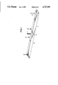
- FIG. 1 is a perspective view of a pair of luminaires connected in end to end abutting relation.
- FIG. 2 is a magnified vertical section taken on the line 2--2 of FIG. 1.
- FIG. 3 is a discontinuous section taken on the line 3--3 of FIG. 2.
- FIG. 4 is a section taken on the line 4--4 of FIG. 2.
- FIG. 1 an installation comprised of a pair of fluorescent luminaires 10 and 11 suspended from hanger rods 12, the upper ends of the hanger rods being secured in conventional fashion to the ceiling structure above the luminaires. It will be understood that while only two luminaires have been disclosed in FIG. 1, which luminaires meet at abutment line 13, that a given installation may include any desired number of end to end connected luminaires.
- the luminaires 10 and 11 may be comprised of aluminum extrusions which are generally u-shaped in transverse section, the extrusions including a central web 14 having upwardly projecting arms 15, 16 at the lateral side edges of the web.
- the arms 15, 16 may include at their upper and lower extremities opposed channels 17, 18 respectively for the reception of the spanner member 19 as will be more fully described hereafter.
- the extrusion from which luminaires 10, 11 is formed also includes an upstanding pair of L-shaped guide members 20, 21 defining inwardly directed opposed longitudinally extending slots 22, 23 respectively.
- the extrusions include vertically directed longitudinally extending flanges 24, 25 spaced from members 20 and 21 respectively, the space 26, 27 between members 20, 24 on the one hand and 21, 25 on the other defining a screw-way within which machine screws 28 may be mounted as will be more fully described hereinafter.
- the luminaires 10, 11 adjacent their respective abutting ends 10', 11' are provided with receiver members 30 and 31 respectively. Since the receiver members 30 and 31 are identical, a description of one such member will suffice. More particularly, the receiver member 30 includes a locking plate 32 having an upstanding boss 33 including a threaded aperture 34.
- the receiver member 30 includes laterally directed flanges 35, 36 mounted within the slots 22, 23 formed on the base of the extrusion. Preferably, the flanges 35, 36 incorporate upstanding projections 37, 38 which closely fill slots 22, 23 respectively to provide frictional but sliding engagement of the flanges within slots 22, 23.
- the receiver members 30, 31 are spaced a short distance inwardly from the abutment line 13 between adjacent luminaires.
- Spanner member 19 which is generally u-shaped in transverse section, includes upstanding side flanges 42, 43 the extremity of the flanges 42, 43 projecting above and below the base portion 44 of the spanner member.
- the flanges 42, 43 of the spanner are received within the opposed slots 17, 18 in the arms 15 and 16 of the extrusion.
- the base plate 44 may include apertures 45 which register with the screw way and are anchored into the screw way by the previously described sheet metal screws or machine screws 28.
- the spanner member 19 is anchored either to one or the other of the luminaires, in the illustrated embodiment to the luminaire 10, it being the function of the aligning joining mechanism to permit anchoring of the spanner to the opposite luminaire, i.e. luminaire 11, after the respective luminaires have been supported from the ceiling structure.
- the base plate 44 of the spanner includes an aperture 46 formed therethrough, a depending tongue 47 formed of the material of the base plate and defining a cam portion being deflected downwardly through the aperture of the spanner.
- the spanner base plate 44 may include a central mounting aperture 48 within which the headed portion 49 of hanger rod 12 is mounted. The connection of the rod to the spanner member base plate may be effected in any desired means and forms no part of the present invention.
- the receiver members 30 and 31 are previously affixed in the manner described adjacent the abutting edges 10', 11' of the respective luminaires 10 and 11.
- the spanner member 19 is secured to one or the other of the luminaires (illustratively by connection to the receiver member 30).
- This connection is effected by sliding the base plate 44 of the spanner member to a position beneath the locking plate 32 of the receiver member 30 in such manner that the cam portion 47 of the spanner member underlies the threaded member 34' mounted in threaded aperture 34.
- the threaded 34' is rotated so as to be driven downwardly against cam surface 47 as shown in FIG. 4.
- Auxiliary locking means for positioning the spanner relative to luminaire 10 such as machine screw 28 may be employed to securely position the spanner member relative to luminaire 10.
- the luminaire 10 with the hanger rod 12 supporting same prepositioned may be mounted to the ceiling in the usual manner.
- the luminaires are thereafter shifted into a position where at the end portions 10', 11' of the respective luminaires approach as closely as possible an abutted position.
- final adjustment is achieved by threading the bolt 34' of receiver 31 downwardly into engagement with cam 47'.
- the luminaire 11 will be camed toward luminaire 10 until a wedged or locking position is achieved by the engagement of the ends 10', 11' of the respective luminaires (FIG. 4). It will thus be observed that tightening of the threaded member 34' of receiver 31 not only functions to lock the two luminaires against separation in a horizontal direction, but also functions to shift the abutting edges of the two luminaires into intimate space free contact.
- the alignment of the respective luminaires is effected principally as a result of the sliding engagement of the side arms of the spanner member with the opposed slots of the respective extrusions, the cam locking function being primarily to prevent separation of the respective luminaires and to assure intimate contact of the abutting edges thereof.
- the final steps of assembling luminaire 11 to luminaire 10 involves merely the tightening of a single threaded member, a task which may readily be accomplished by a worker standing on a ladder or scaffold and certainly far easier than methods heretofor employed which require disassembly, subsequent connection, and reassembly while the worker is on the ladder or scaffold.
Abstract
Description
Claims (8)
Priority Applications (3)
| Application Number | Priority Date | Filing Date | Title |
|---|---|---|---|
| US07/046,105 US4717993A (en) | 1987-05-05 | 1987-05-05 | Aligning joining mechanism for luminaires |
| CA000556239A CA1294595C (en) | 1987-05-05 | 1988-01-11 | Aligning joining mechanism for luminaires |
| GB8806222A GB2204391B (en) | 1987-05-05 | 1988-03-16 | Aligning joining mechanism for luminaires |
Applications Claiming Priority (1)
| Application Number | Priority Date | Filing Date | Title |
|---|---|---|---|
| US07/046,105 US4717993A (en) | 1987-05-05 | 1987-05-05 | Aligning joining mechanism for luminaires |
Publications (1)
| Publication Number | Publication Date |
|---|---|
| US4717993A true US4717993A (en) | 1988-01-05 |
Family
ID=21941650
Family Applications (1)
| Application Number | Title | Priority Date | Filing Date |
|---|---|---|---|
| US07/046,105 Expired - Lifetime US4717993A (en) | 1987-05-05 | 1987-05-05 | Aligning joining mechanism for luminaires |
Country Status (3)
| Country | Link |
|---|---|
| US (1) | US4717993A (en) |
| CA (1) | CA1294595C (en) |
| GB (1) | GB2204391B (en) |
Cited By (11)
| Publication number | Priority date | Publication date | Assignee | Title |
|---|---|---|---|---|
| US5624202A (en) * | 1995-10-19 | 1997-04-29 | Ledalite Architectural Products, Inc. | Integral joint and mounting assembly for suspended linear structures |
| US5658066A (en) * | 1995-07-20 | 1997-08-19 | Linear Lighting Corp. | Joining system for sectional lighting assembly |
| EP0870981A1 (en) * | 1997-04-09 | 1998-10-14 | Koninklijke Philips Electronics N.V. | Luminaire for line illumination |
| US6007217A (en) * | 1998-05-01 | 1999-12-28 | Ledalite Architectural Products, Inc. | Luminaire assembly mounting system |
| US6191355B1 (en) | 1997-11-28 | 2001-02-20 | Hans P. Edelstein | Multi-sectional utility pole having slip-joint conical connections |
| US20060158877A1 (en) * | 2005-01-10 | 2006-07-20 | Lanczy Geza T | Method and apparatus for joining linear lighting fixtures to eliminate sag |
| US20070147053A1 (en) * | 2005-12-23 | 2007-06-28 | Canlyte Inc. | Support Device |
| US7673430B1 (en) | 2006-08-10 | 2010-03-09 | Koninklijke Philips Electronics, N.V | Recessed wall-wash staggered mounting system |
| DE202014106093U1 (en) * | 2014-12-17 | 2016-03-18 | Zumtobel Lighting Gmbh | connecting device |
| US10520170B2 (en) | 2017-08-01 | 2019-12-31 | Pinnacle Architectural Lighting Inc. | Brackets for lighting fixture systems |
| US11313543B2 (en) * | 2019-11-19 | 2022-04-26 | Focal Point, Llc | Screw ramp joiner bracket and system for adjoining light fixture sections |
Citations (6)
| Publication number | Priority date | Publication date | Assignee | Title |
|---|---|---|---|---|
| US2219383A (en) * | 1937-02-13 | 1940-10-29 | Harry J Dillon | Illuminating apparatus |
| US2990470A (en) * | 1958-03-10 | 1961-06-27 | Sunbeam Lighting Company | Reflecting fluorescent light fixture |
| US3011047A (en) * | 1958-02-21 | 1961-11-28 | Joseph H Spaulding | Leveling means for illuminator |
| US3019332A (en) * | 1959-06-03 | 1962-01-30 | Miller Co | Lighting fixture and connector therefor |
| US4419717A (en) * | 1981-10-02 | 1983-12-06 | Edison Price, Incorporated | Ceiling supported lighting fixtures |
| US4424554A (en) * | 1982-09-28 | 1984-01-03 | Lightolier Incorporated | Ceiling fixture with improved mounting means |
-
1987
- 1987-05-05 US US07/046,105 patent/US4717993A/en not_active Expired - Lifetime
-
1988
- 1988-01-11 CA CA000556239A patent/CA1294595C/en not_active Expired - Lifetime
- 1988-03-16 GB GB8806222A patent/GB2204391B/en not_active Expired - Fee Related
Patent Citations (6)
| Publication number | Priority date | Publication date | Assignee | Title |
|---|---|---|---|---|
| US2219383A (en) * | 1937-02-13 | 1940-10-29 | Harry J Dillon | Illuminating apparatus |
| US3011047A (en) * | 1958-02-21 | 1961-11-28 | Joseph H Spaulding | Leveling means for illuminator |
| US2990470A (en) * | 1958-03-10 | 1961-06-27 | Sunbeam Lighting Company | Reflecting fluorescent light fixture |
| US3019332A (en) * | 1959-06-03 | 1962-01-30 | Miller Co | Lighting fixture and connector therefor |
| US4419717A (en) * | 1981-10-02 | 1983-12-06 | Edison Price, Incorporated | Ceiling supported lighting fixtures |
| US4424554A (en) * | 1982-09-28 | 1984-01-03 | Lightolier Incorporated | Ceiling fixture with improved mounting means |
Cited By (14)
| Publication number | Priority date | Publication date | Assignee | Title |
|---|---|---|---|---|
| US5658066A (en) * | 1995-07-20 | 1997-08-19 | Linear Lighting Corp. | Joining system for sectional lighting assembly |
| US5624202A (en) * | 1995-10-19 | 1997-04-29 | Ledalite Architectural Products, Inc. | Integral joint and mounting assembly for suspended linear structures |
| EP0870981A1 (en) * | 1997-04-09 | 1998-10-14 | Koninklijke Philips Electronics N.V. | Luminaire for line illumination |
| US6191355B1 (en) | 1997-11-28 | 2001-02-20 | Hans P. Edelstein | Multi-sectional utility pole having slip-joint conical connections |
| US6007217A (en) * | 1998-05-01 | 1999-12-28 | Ledalite Architectural Products, Inc. | Luminaire assembly mounting system |
| US7380957B2 (en) | 2005-01-10 | 2008-06-03 | Pent Technologies, Inc. | Method and apparatus for joining linear lighting fixtures to eliminate sag |
| US20060158877A1 (en) * | 2005-01-10 | 2006-07-20 | Lanczy Geza T | Method and apparatus for joining linear lighting fixtures to eliminate sag |
| US20070147053A1 (en) * | 2005-12-23 | 2007-06-28 | Canlyte Inc. | Support Device |
| US8057077B2 (en) | 2005-12-23 | 2011-11-15 | Canlyte Inc. | Support device |
| US7673430B1 (en) | 2006-08-10 | 2010-03-09 | Koninklijke Philips Electronics, N.V | Recessed wall-wash staggered mounting system |
| US7856788B2 (en) | 2006-08-10 | 2010-12-28 | Genlyte Thomas Group Llc | Recessed wall-wash staggered mounting method |
| DE202014106093U1 (en) * | 2014-12-17 | 2016-03-18 | Zumtobel Lighting Gmbh | connecting device |
| US10520170B2 (en) | 2017-08-01 | 2019-12-31 | Pinnacle Architectural Lighting Inc. | Brackets for lighting fixture systems |
| US11313543B2 (en) * | 2019-11-19 | 2022-04-26 | Focal Point, Llc | Screw ramp joiner bracket and system for adjoining light fixture sections |
Also Published As
| Publication number | Publication date |
|---|---|
| GB2204391B (en) | 1990-11-14 |
| GB8806222D0 (en) | 1988-04-13 |
| GB2204391A (en) | 1988-11-09 |
| CA1294595C (en) | 1992-01-21 |
Similar Documents
| Publication | Publication Date | Title |
|---|---|---|
| CA2619115C (en) | Adjustable electrical box hanger bar assembly | |
| CA2390970C (en) | Hanger bar assembly | |
| US10333288B2 (en) | Mounting brace assembly for mounting an electrical box | |
| US7271336B2 (en) | Adjustable mounting bracket assembly for mounting an electrical box | |
| US4726781A (en) | Connective mechanism for adjacent fluorescent fixtures | |
| US7510159B2 (en) | Hanger bar centering mechanism | |
| US8240630B2 (en) | Hanger bar for recessed luminaires with integral nail | |
| US4717993A (en) | Aligning joining mechanism for luminaires | |
| AU2010249242A1 (en) | Building Element | |
| US20050247842A1 (en) | Hanger bar assemblies for recessed luminaires | |
| US20090173852A1 (en) | Hand rail system railing connector | |
| US4641805A (en) | Awning support system | |
| US6537155B2 (en) | Counterweight arbor guide system | |
| CA2582945C (en) | Adjustable mounting bracket assembly for mounting an electrical box | |
| JPH0449358A (en) | Support hardware for ceiling base | |
| KR200237599Y1 (en) | support structure of built-in light | |
| AU2002312646B2 (en) | Adjustment device and building element | |
| JP4484581B2 (en) | Fixing structure of bracket device for article mounting | |
| JPH0610008Y2 (en) | Ceiling field structure | |
| KR960009405Y1 (en) | U-chanel anchor | |
| KR200317010Y1 (en) | Fixation device the ceiling for finish panel | |
| JPH0449357A (en) | Ceiling structure | |
| KR19990038843U (en) | Mounting device of ceiling mounted fluorescent lamp | |
| KR20050120094A (en) | Easily installable fluorescent lamp fixtures | |
| GB2422154A (en) | Joint device for roof frame |
Legal Events
| Date | Code | Title | Description |
|---|---|---|---|
| AS | Assignment |
Owner name: LIGHTOLIER INCORPORATED, 100 LIGHTING WAY, SECAUCU Free format text: ASSIGNMENT OF ASSIGNORS INTEREST.;ASSIGNORS:BERNHART, HORST;CHAN, KINGSLEY;REEL/FRAME:004707/0134;SIGNING DATES FROM 19870425 TO 19870427 |
|
| STCF | Information on status: patent grant |
Free format text: PATENTED CASE |
|
| FEPP | Fee payment procedure |
Free format text: PAYOR NUMBER ASSIGNED (ORIGINAL EVENT CODE: ASPN); ENTITY STATUS OF PATENT OWNER: LARGE ENTITY |
|
| FPAY | Fee payment |
Year of fee payment: 4 |
|
| AS | Assignment |
Owner name: GENLYTE GROUP INCORPORATED, THE A CORP. OF DELAWA Free format text: MERGER;ASSIGNOR:LIGHTOLIER INCORPORATED, A CORP. OF NY;REEL/FRAME:006142/0734 Effective date: 19901228 |
|
| FPAY | Fee payment |
Year of fee payment: 8 |
|
| FPAY | Fee payment |
Year of fee payment: 12 |
|
| AS | Assignment |
Owner name: GENLYTE GROUP INCORPORATED, THE, NEW JERSEY Free format text: MERGER;ASSIGNOR:LIGHTOLIER INCORPORATED;REEL/FRAME:010602/0929 Effective date: 19901228 |
|
| AS | Assignment |
Owner name: GENLYTE THOMAS GROUP LLC, KENTUCKY Free format text: NUNC PRO TUNC ASSIGNMENT;ASSIGNOR:GENLYTE GROUP INCORPORATED, THE;REEL/FRAME:010696/0178 Effective date: 20000308 |