US4717240A - Interferometeric beamsplitter - Google Patents
Interferometeric beamsplitter Download PDFInfo
- Publication number
- US4717240A US4717240A US06/888,556 US88855686A US4717240A US 4717240 A US4717240 A US 4717240A US 88855686 A US88855686 A US 88855686A US 4717240 A US4717240 A US 4717240A
- Authority
- US
- United States
- Prior art keywords
- beamsplitter
- optical power
- light
- prism
- optical
- Prior art date
- Legal status (The legal status is an assumption and is not a legal conclusion. Google has not performed a legal analysis and makes no representation as to the accuracy of the status listed.)
- Expired - Fee Related
Links
Images


Classifications
-
- G—PHYSICS
- G02—OPTICS
- G02B—OPTICAL ELEMENTS, SYSTEMS OR APPARATUS
- G02B27/00—Optical systems or apparatus not provided for by any of the groups G02B1/00 - G02B26/00, G02B30/00
- G02B27/10—Beam splitting or combining systems
- G02B27/14—Beam splitting or combining systems operating by reflection only
- G02B27/144—Beam splitting or combining systems operating by reflection only using partially transparent surfaces without spectral selectivity
-
- G—PHYSICS
- G01—MEASURING; TESTING
- G01L—MEASURING FORCE, STRESS, TORQUE, WORK, MECHANICAL POWER, MECHANICAL EFFICIENCY, OR FLUID PRESSURE
- G01L1/00—Measuring force or stress, in general
- G01L1/10—Measuring force or stress, in general by measuring variations of frequency of stressed vibrating elements, e.g. of stressed strings
- G01L1/103—Measuring force or stress, in general by measuring variations of frequency of stressed vibrating elements, e.g. of stressed strings optical excitation or measuring of vibrations
-
- G—PHYSICS
- G01—MEASURING; TESTING
- G01L—MEASURING FORCE, STRESS, TORQUE, WORK, MECHANICAL POWER, MECHANICAL EFFICIENCY, OR FLUID PRESSURE
- G01L1/00—Measuring force or stress, in general
- G01L1/16—Measuring force or stress, in general using properties of piezoelectric devices
- G01L1/162—Measuring force or stress, in general using properties of piezoelectric devices using piezoelectric resonators
- G01L1/167—Measuring force or stress, in general using properties of piezoelectric devices using piezoelectric resonators optical excitation or measuring of vibrations
-
- G—PHYSICS
- G01—MEASURING; TESTING
- G01L—MEASURING FORCE, STRESS, TORQUE, WORK, MECHANICAL POWER, MECHANICAL EFFICIENCY, OR FLUID PRESSURE
- G01L1/00—Measuring force or stress, in general
- G01L1/24—Measuring force or stress, in general by measuring variations of optical properties of material when it is stressed, e.g. by photoelastic stress analysis using infrared, visible light, ultraviolet
-
- G—PHYSICS
- G01—MEASURING; TESTING
- G01L—MEASURING FORCE, STRESS, TORQUE, WORK, MECHANICAL POWER, MECHANICAL EFFICIENCY, OR FLUID PRESSURE
- G01L9/00—Measuring steady of quasi-steady pressure of fluid or fluent solid material by electric or magnetic pressure-sensitive elements; Transmitting or indicating the displacement of mechanical pressure-sensitive elements, used to measure the steady or quasi-steady pressure of a fluid or fluent solid material, by electric or magnetic means
- G01L9/0001—Transmitting or indicating the displacement of elastically deformable gauges by electric, electro-mechanical, magnetic or electro-magnetic means
- G01L9/0008—Transmitting or indicating the displacement of elastically deformable gauges by electric, electro-mechanical, magnetic or electro-magnetic means using vibrations
- G01L9/0022—Transmitting or indicating the displacement of elastically deformable gauges by electric, electro-mechanical, magnetic or electro-magnetic means using vibrations of a piezoelectric element
- G01L9/0023—Optical excitation or measuring
-
- G—PHYSICS
- G02—OPTICS
- G02B—OPTICAL ELEMENTS, SYSTEMS OR APPARATUS
- G02B6/00—Light guides; Structural details of arrangements comprising light guides and other optical elements, e.g. couplings
- G02B6/24—Coupling light guides
- G02B6/26—Optical coupling means
- G02B6/28—Optical coupling means having data bus means, i.e. plural waveguides interconnected and providing an inherently bidirectional system by mixing and splitting signals
- G02B6/2804—Optical coupling means having data bus means, i.e. plural waveguides interconnected and providing an inherently bidirectional system by mixing and splitting signals forming multipart couplers without wavelength selective elements, e.g. "T" couplers, star couplers
- G02B6/2821—Optical coupling means having data bus means, i.e. plural waveguides interconnected and providing an inherently bidirectional system by mixing and splitting signals forming multipart couplers without wavelength selective elements, e.g. "T" couplers, star couplers using lateral coupling between contiguous fibres to split or combine optical signals
Definitions
- This invention relates to the field of fiber optic based communications and more particularly to apparatus and methods for dividing and combining optical power on an optical fiber at a measurement site. More particularly, a single optical fiber carries optical power to a remote site where the optical beam is split, the split beams interacting with a target resonant element. After recombining the interferometrically modulated output beams are used to drive the resonator and communicate the resonator frequency to a location where it may be used.
- the beamsplitter of the present invention enables the necessary optical beam splitting and recombining functions.
- resonant mechanical structure generally refer to beam (hollow beam, cantilevered beam and cantilevered hollow beam, and double- or other multiple-beam elements), and ribbon, wire or other articles of manufacture, and their equivalents, all of which can be resonated at particular oscillation frequencies.
- tuning fork structures of the single- and double-ended varieties, as well as multiple tine tuning fork structures.
- Fiber optic means and equivalent terms refer to single or multiple communication paths.
- the term "radiant power", light, optical power or light flux includes electromagnetic power of wavelengths between 0.1 and 100 micrometers, and specifically includes infrared, ultraviolet, and visible light.
- light flux refers to the number of photons that pass through a plane per unit of time, and is measured in watts.
- radiant energy may be referred to generally and without limitation as “light” or “optical” power.
- Such radiant power may also be described as “steady” or “continuous” or “unmodulated” in order to distinguish it from radiant power signals which are modified to carry information.
- the term “radiant power” specifically includes coherent and incoherent light power.
- Modulation is used broadly herein, and it is intended to means modifying (or the modification of) some characteristic or characteristics of a light beam so that it varies in step with the instantaneous value of another signal, and specifically may be used herein to describe amplitude modulation and frequency modulation.
- Unmodulated optical power refers to optical power which is unmodulated in this sense.
- “Monochromatic” refers to radiant power composed of a single wavelength.
- Coldlight refers to radiant power having rays which are rendered substantially parallel to a certain line or direction.
- Fluid includes gases and/or liquids.
- force is used to describe any physical parameter or phenomenon capable of moving a body or modifying its motion, and specifically includes force exerted per unit area (pressure) and any parameter or phenomenon capable of conversion to pressure.
- Photothermal effect and “photokinetic effect”, as used herein, refer to the phenomenon wherein photons striking a suitable surface or surface coating cause localized heating, such heating being sufficient to cause localized expansion of the coating or substrate, and thus producing motion.
- the present invention relates to beamsplitter means for use with a sensor at a sensor site in which the beamsplitter divides light from a source into separate beams for interferometric modulation by the resonant element.
- the modulated optical power is used to energize the resonator and to communicate the resonant frequency to a location where it may be used.
- the present disclosure includes two specific embodiments: the first preferred embodiment makes use of a prism beamsplitter of a particular configuration.
- an optical fiber beamsplitter is used to achieve the sensitive light handling needed for the sensor. Variations of these embodiments are also described herein.
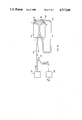
- FIG. 1 is a simplified block diagram of the invention
- FIGS. 2 through 5 show a prism form of the invention and its manufacture
- FIG. 6 is a plan view of the prism showing its major elements
- FIG. 7 illustrates the Michelson interferometric principles applied with the invention
- FIG. 8 show the relationship of the output light intensity with respect to motion of the moving mirror 84
- FIG. 9 is Equation I, showing the modulation of light by an ideal Michelson interferometer
- FIG. 10 illustrates improvements to a simle Michelson interferometer useful with the invention
- FIG. 11 is Equation II, which gives a expression for light modulation from a Michelson interferometer
- FIGS. 12 through 15 show the prism beamsplitter form of the invention.
- FIG. 16 shows a multiple path optical fiber form of the invention.
- FIG. 1 a generalized block diagram of the self-oscillating resonant sensor system 10 is illustrated, showing an optically-powered resonant sensor 20, a light source 22, a conventional beam splitter 25, an optical fiber 24 pathway, a special beamsplitter means 23, detection means 26, output means 28 for producing an output signal 30, and resonator 108.
- Light beams a and b represent the split interferometer beams which interact with the resonator.
- Beam d represents the drive light path to the resonator, while light beam m represents modulated light being returned for detection.
- the prism beam splitter of the present invention is prepared from a cube 27 ABCDEFGH (see FIG. 2) of fused silica or the equivalent, and having a half-mirror 80 in the BDHF plane (see FIG. 3) thereof.
- the half mirror should divide the light equally between transmission and reflection without preference for polarization.
- a first cut (FIG. 4) material is removed along the ABGH plane.
- a second cut material is removed along the BCHE plane (E is now an imaginary location in space), leaving a pyramid (see FIG. 5) having a square base ABCD and apex H wehrein edge DH is perpendicular to the ABCD plane.
- a "wall” or “skirt” may be left at the bottom of the base to aid in mounting and manufacture of the prism.
- FIG. 6 a plan view of the prism, shows prism 110 entrance face 112, first 45-degree prism roof face 114, second 45-degree prism roof face 116, and prism exit face 120.
- the prism bottom surface 118 is not visible.
- the half mirror beamsplitter 80 is seen edge-on as a line through BD and H.
- first collimator lens 76 collimator lens 76
- first output lens 78 prism beamsplitter 80
- first (or fixed) mirror 82 prism beamsplitter 80
- second (or target) mirror 84 transmitted light flux 86.
- FIG. 7 shows a simplified conventional Michelson interferometer.
- Unmodulated optical power from a source (not shown) is supplied via an optical fiber 24 and collimated by lens 76.
- This input light beam here shown as (I 0 ) is split by beamsplitter 80 which may conveniently be a conventional cube beamsplitter.
- Light flux (I 0 ) is divided into two portions without polarization preference for the purposes of this embodiment.
- Mirrors 82 and 84 return light energy to the beamsplitter. Two output beams result.
- One beam is collected by lens 78 which exits at 86 as transmitted beam (I t ).
- the other beam (I r ) is returned via optical fiber pathway 24.
- the first mirror 82 is fixed and the second mirror, 84, is a moving or vibrating surface having reflective characteristics.
- this may be viewed as a portion of a resonant element.
- the transmitted light flux (I t ) is modulated as shown in FIG. 8 for the case of monochromatic light which is parallel through the interferometer. Mirror and beamsplitter losses may be ignored for the present illustrative purposes.
- the variation of I t with motion of second mirror 84 is given by Equation I (see FIG. 9).
- the conventional simple Michelson interferometer configuration shown in FIGS. 7 and 8 is not ideally suited for use in combination with a resonant element as a moving mirror.
- the system can be advantageously modified for use in combination with resonant elements, as in the present invention.
- FIG. 10 There is shown in FIG. 10 light source 22, optical fiber 24, beamsplitter means 25, and detection means 26, as well as first collimator lens 76, first output lens 78, beamsplitter 80, first fixed mirror 82, and target mirror 84.
- lenses 76 and 78 are readjusted so as to focus the light beam through the interferometer to a focus on the two mirrors 82, 84.
- the small beam focus at mirror 84 is then compatible with the small area reflective surface of a micro-sized resonant element. That is, the mirror 84 is located on the surface of the resonator.
- the contrast and depth of modulation of the light intereference as mirror 84 moves decreases as the path length of the interferometer arms becomes unequal.
- the degree of modulation of light power (I t ), 86 in FIG. 10 is essentially as large as in the conventional parallel beam interferometer, FIG. 7.
- the change of transmitted light power as mirror 84 makes small changes in position is maximized as shown in Equation II, FIG. 11.
- the focussed beam Michelson interferometer is sensitive enough to be used in the feedback loop of a self-oscillating resonant element.
- the convergent beam Michelson interferometer is much less sensitive to tilt misadjustment of the mirrors 82 and 84.
- the Michelson interferometer based techique may be used with a wide variety of resonant structures, such as ribbons vibrating in torsion or flexure, tuning forks, double tuning forks (DTF's), cantilever beams and their sustitutes and equivalents.
- the modulated output beam should be used to drive the resonant element. This may be accomplished, for example, by directing the modulated light to a metal film on the resonator, where the metal film can couple the optical power to motion of the resonator by the previously described photokinetic effect.
- the phase should be selected to optimize positive feedback.
- the preferred embodiments have inherent rejection of common mode motions of the resonant element as a whole relative to the mounting structure and light delivery system.
- any independent motion of beamsplitter 80 and fixed mirror 82 relative to the resonator will result in unwanted modulation of the light.
- FIG. 12 shows the special prism best.
- the fiber optic or integrated optic version of the beamsplitter is shown best in FIG. 16, described hereinafter.
- the split beams terminate on the resonator at locations analogous to those of coatings at locations 82 and 84. Both locations move in push-pull fashion, doubling thereby the sensitivity and eliminating sensitivity to common mode motion of the resonator as a whole relative to the rest of the optical system.
- the resulting complementary modulated light beam returned toward the source, carries the modulating frequency, and thus the resonant element operating frequency, back to the remote location.
- a prism beamsplitter may be used to avoid the undesirable effects of ambient vibration and thermally induced dimensional change. It is shown in FIGS. 12 through 15.
- the special prism beamsplitter 110 used is designed such that both Michelson interferometer beams can be made parallel so that they can be reflected from two adjacent locations on a moving resonator which locations have differential motion in the desired mode of resonance. In this way light modulation is the result of the desired resonant vibration as distinct from common mode motion of the resonator with respect to the beamsplitter prism or mounting structure.
- FIG. 12 optical fiber 24, first collimator lens 76, output lens 78, resonator mounts 92, torsional ribbon resonator 108, special prism beamsplitter 110, prism entrance face 112, fist 45-degree prism roof face 114, second 45-degree prism roof face 116, and prism exit face 120.
- FIG. 13 there is shown prism entrance face 112, first 45-degree prism roof face 114 and prism bottom surface 118.
- Shown in FIG. 14 are second 45-degree prism roof face 116, prism bottom surface 188, and prism exit face 120.
- FIG. 15 shows torsional ribbon resonator 108, entrance prism facd 112, first 45-degree prism roof face 114 and prism bottom surface 118.
- the resonant element shown in FIGS. 12 and 15 is a torsional ribbon 108 such that, as the reflecting surface 82 (see FIG. 15) moves toward the beamsplitter prism 110, reflecting surface 84 moves away.
- Common mode motion of reflecting surfaces 82 and 84 together affects both arms of the interferometric arrangement equally so as not to contribute to light modulation.
- the desired torsional mode has a push-pull effect on the interferometer arms and results in high modulation sensitivity.
- FIGS. 12 through 15 depict various projections of the novel prism beamsplitter.
- the light paths are somewhat complex to visualize three-dimensionally, thus FIGS. 12 through 15 show the prism beamsplitter in plan view and the front, side and rear elevation views.
- Incident light flux I 0 enters prism beamsplitter 110 through face 112 and is divided by the beamsplitter half-mirror coating 80.
- the transmitted portion of the light flux meets 45-degree roof face 114 and is directed downwards through the bottom surface 118 of the prism beamsplitter 110 to focus on the resonator 108 at 82.
- the portion of the light flux reflected by beamsplitter 80 of prism 110 strikes 45-degree roof face 116 and is similarly directed downwards through bottom surface 118 of prism 110 to focus on the resonator 108 at coating 84.
- the modulated output beam I t exits face 120 and can be used to drive the resonator in any of the various ways known to artisans in the field, including the methods known as photokinetic, and "opto-electric” and “electro-optic", including the step of conversion of light to electricity.
- the input light (I 0 ) and exit light (I t ) paths can be made (by refraction at the air - prism interface) to lie along the axis of the resonator and so produce a very compact optically driven resonator package.
- light enters face CDH (112) and is split by the coating BDH (80) with transmitted and reflected split beams being totally internally reflected from faces ABH (114) and BCH (116) respectively before exiting portions of base ABD (118) and BCD respectively to impinge on retro-reflecting surfaces of the resonator.
- the resulting recombined and modulated transmitted beam exits face ADH (120) and the recombined and modulated reflected beam exits face CDH (112), back towards the source.
- surfaces 112, 118, and 120 may be antireflection coated. If surfaces 114 and 116 are not to be metalized, the prism refractive index should be sufficiently high to ensure total internal reflection.
- a Michelson interferometer can be constructed using optical fibers and a fiber splitter so as to eliminate the need for bulk optic components.
- the optical fibers transporting the split beams may terminate close to reflective locations on the resonator and so sense differential motion while discriminating against common mode undesired motions.
- an integrated optic splitter may be used.
- FIG. 16 there is shown a simplified view of the invention utilizing light source 22, fiber optic 24 pathway, fiber splitter 25, detection means 28, signal output 30, reflective layers or mirrors 82 and 84 on the surface of resonator 108, a four port fiber optic or integrated optic coupler 131, a drive light path fiber optic 133 pathway, providing light modulated at the natural frequency of the resonator which can be used to drive the resonator.
- the apparatus of FIG. 16 operates with a steady light source 22 providing a beam of steady light along fiber optic pathway 24 to four-port coupler 131 at entry port t, in which coupler the incoming light is split into two pathways internally to shine on mirrors 82 and 84 via ports v and w, respectively.
- the mirrors 82 and 84 are surface areas on resonator 108. Alternating torsional oscillations of the resonator 108 vary the optical path of the light 116 reflected by the mirrors (i.e., modulate the output beams according to the oscillation frequency of the resonator) back into ports v and w.
- the resonant frequency of resonator 108 may be varied in relation to an external value, which may be a measurand.
- a portion of the modulated light is returned along fiber optic 24 pathway carrying the frequency of the resonator and another portion is used to drive the resonator by positive feedback by fiber optic 133 pathway.
- This latter portion of the modulated light is used to drive the resonator 108 into resonant vibrations, such as by the photokinetic effect previously described, or such other methods as are known to those persons skilled in the art.
- the ports of the coupler v and w may be anti-reflection coated to increase modulation efficiency, and if reflective locations 82 and 84 are not closely adjacent to the ports v and w, some means of improving light collimation in the intervening space or of imaging the fiber ends on to the reflective locations may be employed.
Landscapes
- Physics & Mathematics (AREA)
- General Physics & Mathematics (AREA)
- Spectroscopy & Molecular Physics (AREA)
- Optics & Photonics (AREA)
- Instruments For Measurement Of Length By Optical Means (AREA)
Abstract
Description
Claims (8)
Priority Applications (1)
| Application Number | Priority Date | Filing Date | Title |
|---|---|---|---|
| US06/888,556 US4717240A (en) | 1986-07-21 | 1986-07-21 | Interferometeric beamsplitter |
Applications Claiming Priority (1)
| Application Number | Priority Date | Filing Date | Title |
|---|---|---|---|
| US06/888,556 US4717240A (en) | 1986-07-21 | 1986-07-21 | Interferometeric beamsplitter |
Publications (1)
| Publication Number | Publication Date |
|---|---|
| US4717240A true US4717240A (en) | 1988-01-05 |
Family
ID=25393397
Family Applications (1)
| Application Number | Title | Priority Date | Filing Date |
|---|---|---|---|
| US06/888,556 Expired - Fee Related US4717240A (en) | 1986-07-21 | 1986-07-21 | Interferometeric beamsplitter |
Country Status (1)
| Country | Link |
|---|---|
| US (1) | US4717240A (en) |
Cited By (7)
| Publication number | Priority date | Publication date | Assignee | Title |
|---|---|---|---|---|
| WO1991009271A1 (en) * | 1989-12-13 | 1991-06-27 | Werner Tabarelli | Interferometer head and interferometer arrangement using it |
| US5245473A (en) * | 1991-06-28 | 1993-09-14 | Sandia Corporation | Apparatus and method for laser velocity interferometry |
| US5521707A (en) * | 1991-08-21 | 1996-05-28 | Apeiron, Inc. | Laser scanning method and apparatus for rapid precision measurement of thread form |
| US5727110A (en) * | 1995-09-29 | 1998-03-10 | Rosemount Inc. | Electro-optic interface for field instrument |
| US5771114A (en) * | 1995-09-29 | 1998-06-23 | Rosemount Inc. | Optical interface with safety shutdown |
| US5825802A (en) * | 1991-11-25 | 1998-10-20 | Elkins; Robin K. | Optical elements for lasers |
| US20060284059A1 (en) * | 2005-06-21 | 2006-12-21 | Grot Annette C | Optical fiber based surface sensing system that enables spectral multiplexing |
Citations (4)
| Publication number | Priority date | Publication date | Assignee | Title |
|---|---|---|---|---|
| US4009940A (en) * | 1974-04-27 | 1977-03-01 | Takata Ophthalmic Instruments Co., Ltd. | Apparatus for producing optical interference pattern with continuously variable fringe spacing |
| US4329775A (en) * | 1977-09-19 | 1982-05-18 | The Foxboro Co. | Pressure measuring apparatus using vibratable wire |
| US4355900A (en) * | 1980-08-08 | 1982-10-26 | The United States Of America As Represented By The Secretary Of The Air Force | Self-calibrating interferometer |
| US4647206A (en) * | 1983-09-23 | 1987-03-03 | Carl-Zeiss-Stiftung | Multi-coordinate measuring machine |
-
1986
- 1986-07-21 US US06/888,556 patent/US4717240A/en not_active Expired - Fee Related
Patent Citations (4)
| Publication number | Priority date | Publication date | Assignee | Title |
|---|---|---|---|---|
| US4009940A (en) * | 1974-04-27 | 1977-03-01 | Takata Ophthalmic Instruments Co., Ltd. | Apparatus for producing optical interference pattern with continuously variable fringe spacing |
| US4329775A (en) * | 1977-09-19 | 1982-05-18 | The Foxboro Co. | Pressure measuring apparatus using vibratable wire |
| US4355900A (en) * | 1980-08-08 | 1982-10-26 | The United States Of America As Represented By The Secretary Of The Air Force | Self-calibrating interferometer |
| US4647206A (en) * | 1983-09-23 | 1987-03-03 | Carl-Zeiss-Stiftung | Multi-coordinate measuring machine |
Cited By (9)
| Publication number | Priority date | Publication date | Assignee | Title |
|---|---|---|---|---|
| WO1991009271A1 (en) * | 1989-12-13 | 1991-06-27 | Werner Tabarelli | Interferometer head and interferometer arrangement using it |
| US5245473A (en) * | 1991-06-28 | 1993-09-14 | Sandia Corporation | Apparatus and method for laser velocity interferometry |
| US5521707A (en) * | 1991-08-21 | 1996-05-28 | Apeiron, Inc. | Laser scanning method and apparatus for rapid precision measurement of thread form |
| US5712706A (en) * | 1991-08-21 | 1998-01-27 | M&M Precision Systems Corporation | Laser scanning method and apparatus for rapid precision measurement of thread form |
| US5825802A (en) * | 1991-11-25 | 1998-10-20 | Elkins; Robin K. | Optical elements for lasers |
| US5727110A (en) * | 1995-09-29 | 1998-03-10 | Rosemount Inc. | Electro-optic interface for field instrument |
| US5771114A (en) * | 1995-09-29 | 1998-06-23 | Rosemount Inc. | Optical interface with safety shutdown |
| US20060284059A1 (en) * | 2005-06-21 | 2006-12-21 | Grot Annette C | Optical fiber based surface sensing system that enables spectral multiplexing |
| US7155077B1 (en) * | 2005-06-21 | 2006-12-26 | Agilent Technologies, Inc | Optical fiber based surface sensing system that enables spectral multiplexing |
Similar Documents
| Publication | Publication Date | Title |
|---|---|---|
| EP0331671B1 (en) | Self-oscillating, optical resonant sensor | |
| Lu et al. | Review of micromachined optical accelerometers: From mg to sub-μg | |
| US5091983A (en) | Optical modulation apparatus and measurement method | |
| US6925213B2 (en) | Micromachined fiber optic sensors | |
| US5891747A (en) | Interferometric fiber optic displacement sensor | |
| US7428054B2 (en) | Micro-optical sensor system for pressure, acceleration, and pressure gradient measurements | |
| US5017010A (en) | High sensitivity position sensor and method | |
| US4772786A (en) | Photothermal oscillator force sensor | |
| US4446543A (en) | Optical resonator single-mode fiber hydrophone | |
| US4627728A (en) | Compensated Fabry Perot sensor | |
| CA2921227C (en) | All-optical system responsive to motion and optical module for use in the same | |
| JPH1123223A (en) | Unbalanced fiber-optic Michelson interferometer as optical pickoff | |
| NO871064L (en) | PROCEDURE AND APPARATUS FOR FEELING A SIZE SIZE. | |
| CA1223954A (en) | Optical fibre hydrophone | |
| US4717240A (en) | Interferometeric beamsplitter | |
| US5195374A (en) | Sensor systems | |
| US5521884A (en) | Vibrating element transducer | |
| EP0505177B1 (en) | Vibrating sensor | |
| US5265479A (en) | Micro resonator | |
| Hellesø et al. | Interferometric displacement sensor made by integrated optics on glass | |
| RU2057285C1 (en) | Fibre-optics displacement transducer | |
| CN116773851B (en) | Cavity-based optical-mechanical MEMS accelerometer with enhanced cavity optical performance | |
| AU8022787A (en) | Self-oscillating, optical resonant sensor | |
| JP2726860B2 (en) | Optical vibration force sensor | |
| Ghosh et al. | Packaging single fiber probe based reflective sensors |
Legal Events
| Date | Code | Title | Description |
|---|---|---|---|
| AS | Assignment |
Owner name: FOXBORO COMPANY THE, FOXBORO, MA, A MA CORP Free format text: ASSIGNMENT OF ASSIGNORS INTEREST.;ASSIGNOR:GILBY, ANTHONY C.;REEL/FRAME:004600/0472 Effective date: 19860721 Owner name: FOXBORO COMPANY THE, A MA CORP,MASSACHUSETTS Free format text: ASSIGNMENT OF ASSIGNORS INTEREST;ASSIGNOR:GILBY, ANTHONY C.;REEL/FRAME:004600/0472 Effective date: 19860721 |
|
| AS | Assignment |
Owner name: BANKERS TRUST COMPANY, 280 PARK AVENUE, NEW YORK, Free format text: SECURITY INTEREST;ASSIGNOR:FOXBORO COMPANY, THE, A CORP OF MA;REEL/FRAME:005477/0603 Effective date: 19900905 |
|
| FPAY | Fee payment |
Year of fee payment: 4 |
|
| FPAY | Fee payment |
Year of fee payment: 8 |
|
| REMI | Maintenance fee reminder mailed | ||
| LAPS | Lapse for failure to pay maintenance fees | ||
| FP | Lapsed due to failure to pay maintenance fee |
Effective date: 20000105 |
|
| STCH | Information on status: patent discontinuation |
Free format text: PATENT EXPIRED DUE TO NONPAYMENT OF MAINTENANCE FEES UNDER 37 CFR 1.362 |