US4716694A - Wear resistant panel arrangement - Google Patents
Wear resistant panel arrangement Download PDFInfo
- Publication number
- US4716694A US4716694A US06/934,621 US93462186A US4716694A US 4716694 A US4716694 A US 4716694A US 93462186 A US93462186 A US 93462186A US 4716694 A US4716694 A US 4716694A
- Authority
- US
- United States
- Prior art keywords
- panel
- recess
- wear resistant
- panels
- support frame
- Prior art date
- Legal status (The legal status is an assumption and is not a legal conclusion. Google has not performed a legal analysis and makes no representation as to the accuracy of the status listed.)
- Expired - Lifetime
Links
- 230000002093 peripheral effect Effects 0.000 claims abstract description 10
- 239000000463 material Substances 0.000 claims abstract description 9
- 229920002635 polyurethane Polymers 0.000 abstract description 3
- 239000004814 polyurethane Substances 0.000 abstract description 3
- 238000012216 screening Methods 0.000 description 5
- 229910000831 Steel Inorganic materials 0.000 description 1
- 238000003780 insertion Methods 0.000 description 1
- 230000037431 insertion Effects 0.000 description 1
- 239000002184 metal Substances 0.000 description 1
- 229920003023 plastic Polymers 0.000 description 1
- 239000004033 plastic Substances 0.000 description 1
- 239000010959 steel Substances 0.000 description 1
Images


Classifications
-
- F—MECHANICAL ENGINEERING; LIGHTING; HEATING; WEAPONS; BLASTING
- F16—ENGINEERING ELEMENTS AND UNITS; GENERAL MEASURES FOR PRODUCING AND MAINTAINING EFFECTIVE FUNCTIONING OF MACHINES OR INSTALLATIONS; THERMAL INSULATION IN GENERAL
- F16B—DEVICES FOR FASTENING OR SECURING CONSTRUCTIONAL ELEMENTS OR MACHINE PARTS TOGETHER, e.g. NAILS, BOLTS, CIRCLIPS, CLAMPS, CLIPS OR WEDGES; JOINTS OR JOINTING
- F16B5/00—Joining sheets or plates, e.g. panels, to one another or to strips or bars parallel to them
- F16B5/07—Joining sheets or plates, e.g. panels, to one another or to strips or bars parallel to them by means of multiple interengaging protrusions on the surfaces, e.g. hooks, coils
-
- E—FIXED CONSTRUCTIONS
- E01—CONSTRUCTION OF ROADS, RAILWAYS, OR BRIDGES
- E01C—CONSTRUCTION OF, OR SURFACES FOR, ROADS, SPORTS GROUNDS, OR THE LIKE; MACHINES OR AUXILIARY TOOLS FOR CONSTRUCTION OR REPAIR
- E01C23/00—Auxiliary devices or arrangements for constructing, repairing, reconditioning, or taking-up road or like surfaces
- E01C23/06—Devices or arrangements for working the finished surface; Devices for repairing or reconditioning the surface of damaged paving; Recycling in place or on the road
- E01C23/12—Devices or arrangements for working the finished surface; Devices for repairing or reconditioning the surface of damaged paving; Recycling in place or on the road for taking-up, tearing-up, or full-depth breaking-up paving, e.g. sett extractor
- E01C23/121—Devices or arrangements for working the finished surface; Devices for repairing or reconditioning the surface of damaged paving; Recycling in place or on the road for taking-up, tearing-up, or full-depth breaking-up paving, e.g. sett extractor with non-powered tools, e.g. rippers
-
- E—FIXED CONSTRUCTIONS
- E01—CONSTRUCTION OF ROADS, RAILWAYS, OR BRIDGES
- E01C—CONSTRUCTION OF, OR SURFACES FOR, ROADS, SPORTS GROUNDS, OR THE LIKE; MACHINES OR AUXILIARY TOOLS FOR CONSTRUCTION OR REPAIR
- E01C5/00—Pavings made of prefabricated single units
- E01C5/20—Pavings made of prefabricated single units made of units of plastics, e.g. concrete with plastics, linoleum
-
- E—FIXED CONSTRUCTIONS
- E04—BUILDING
- E04F—FINISHING WORK ON BUILDINGS, e.g. STAIRS, FLOORS
- E04F15/00—Flooring
- E04F15/02—Flooring or floor layers composed of a number of similar elements
- E04F15/024—Sectional false floors, e.g. computer floors
- E04F15/02405—Floor panels
-
- E—FIXED CONSTRUCTIONS
- E04—BUILDING
- E04F—FINISHING WORK ON BUILDINGS, e.g. STAIRS, FLOORS
- E04F15/00—Flooring
- E04F15/02—Flooring or floor layers composed of a number of similar elements
- E04F15/10—Flooring or floor layers composed of a number of similar elements of other materials, e.g. fibrous or chipped materials, organic plastics, magnesite tiles, hardboard, or with a top layer of other materials
Definitions
- This invention relates to a wear resistant panel arrangement.
- the invention relates to a fastening arrangement for a wear resistant panel arrangement for fastening panels to a support structure.
- the wear resistant panel arrangement may, for example, be screening panels for screening ores, or lining panels for lining chutes, bins, etc., used in the handling of ores.
- the panels have protrusions along their peripheral regions and are arranged in an abutting side-by-side relationship on a support frame, with the protrusions engaging a support frame through apertures in the support frame through which the protrusions extend.
- This arrangement ensures a secure fastening of the panels to the support frame.
- the protrusions When it is desired to replace a panel the protrusions must be withdrawn through the apertures in the support frame. This requires force and while it is not normally any problem, it could be difficult to do so in certain circumstances, for example where there is limited working space within which to manipulate a release tool.
- a wear resistant panel having protrusions of a resiliently deformable material located in the vicinity of the peripheral region of the panel by means of which the panel can be removably secured to a support structure, the panel being provided with at least one recess in the peripheral region of the panel into which recess a release tool can be forced to exert pressure to facilitate the removal of the panel from the support structure.
- the recess may conveniently be provided at or near a corner of the panel. Conveniently, a plurality of such recesses may be provided, and a recess may be provided at or near each side of each corner of the panel.
- the recess may be of a tapering configuration, tapering downwardly from the working surface of the panel to terminate at a zero depth some distance above the underside of the panel.
- the purpose of the tapering configuration of the recess is to prevent material from escaping from the working surface of the panel to the underside of the panel.
- recesses on identical panels may be provided in identical positions on the peripheral regions of the panels so that when the panels are arranged side-by-side on a supporting structure, the recesses are in register with each other and thus ensure that a release tool can conveniently be inserted into the full recess thus formed by the two half recesses on the abutting panels.
- a further recess may be provided on the rear or non-working surface of the panel immediately below the first recess.
- the function of the further recess is to further facilitate a release tool being forced underneath the panel between the panel and the support structure to thereby further facilitate the removal of the panel from the support structure.
- the second recess may be provided underneath a corner of the panel, and conveniently, a plurality of such recesses may be provided, one underneath each corner of the panel.
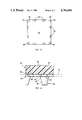
- FIG. 1 shows a framentary plan view of a support frame for supporting a wear resistant panel arrangement in accordance with the invention
- FIG. 2 shows a plan view of a plurality of panels in accordance with the invention arranged side-by-side on the support frame of FIG. 1;
- FIG. 3 shows a bottom plan view of one of the panels shown in FIG. 2;
- FIG. 4 shows on an enlarged scale a section on line IV--IV of FIG. 2;
- FIG. 5 shows a sectional view on line V--V of FIG. 2;
- FIG. 6 shows the arrangement shown in FIG. 5 during a removal of a panel from the support frame.
- reference numeral 10 indicates in general a fragmentary plan view of a support frame for supporting a wear resistant panel arrangement in accordance with the invention.
- the support frame includes a plurality of intersecting support members 12 and 14 having apertures 16 for securing protrusions on the wear resistant panel arrangement which will be described with reference to the other Figures.
- the support frame 10 is conveniently fabricated of a suitable metal such as steel.
- the panels 18 are of a suitable wear resistant, resiliently deformable material such as a suitable synthetic plastics material, for example polyurethane.
- the panels may be screening panels with screening apertures (not shown), or they may be lining panels, in which case no screening apertures are provided.
- each panel 18 At the periphery of each panel 18, near each corner of the panel, there is provided a recess 20. Where two such panels abut each other side-by-side, as shown in FIG. 2, the half recesses on each panel register with each other and thereby form full recesses.
- the recesses 20 are described in greater detail with reference to FIGS. 4, 5 and 6.
- the panel has a series of protrusions 22 of a resiliently deformable material, for example polyurethane, spaced from each other along the peripheral region of the panel.
- Each protrusion 22 has a stem 22 and a tapering portion 26 which are shown in greater detail in FIG. 4.
- FIG. 3 there is shown a second recess 28 in the rear or non-working surface of the panel below each corner.
- the recess 28 has chamfered sides 30 and it is shown in greater detail in FIG. 4.
- FIG. 4 a fragmentary sectional view of the panel 18 on an enlarged scale is shown.
- the panel is secured to the support frame 10 (shown in dotted lines) by means of the protrusions 22 which fit though the apertures 16 in the support frame.
- the tapering portion 26 of each protrusion facilitates the protrusion being fitted through the aperture 16 but the enlarged shoulder 32 on the protrusion, which is larger than the aperture 16, ensures that the protrusion, and thus the panel 18, are securely held on the support frame 16.
- the recess 20 on the peripheral region of the panel 18 is of a tapering shape which converges downwardly from the wearing surface 34 of the panel to a zero dimension some distance above the rear surface 36 of the panel.
- the recess 20 is positioned immediately above the recess 28 underneath each corner of the panel 28.
- the tapering shape of the recess 20 prevents material, such as material being screened on the working surface 34, from escaping from the working surface 34 to the bottom surface 36 of the panel.
- FIG. 5 a fragmentary cross-sectional view is shown of two panels 18 abutting side-by-side and being secured to the support frame 10 by means of their protrusions 22.
- the half recesses 20 on each panel 18 are in register with one another and thereby form a tapering full recess as shown in the drawing.
- the second recesses 28 on the panels are in register with one another.
- a release tool 38 which is shown in dotted lines, can be inserted through the full recess formed by the half recesses 20 and can be manipulated through the recesses past the chamfered faces 30 on the second recesses 28, and into one of the second recesses 28 to lift the corner of the panel. This arrangement is shown in greater detail in FIG. 6.
- the release tool 38 is shown in position in one of the recesses 28 beneath the corner of one of the panels 18.
- the end 40 of the release tool which is in position in one of the recesses 28, and which rests on the support frame 10, can exert an upward lifting force against the corner of the panel.
- the protrusion 22 can be deformed sufficiently to permit the protrusion to be withdrawn through the aperture 16 in the support frame 10. Thereby the panel can be released from the support frame 10.
- the recess 20 on each panel 18 facilitates the insertion of a release tool 38 between two abutting panels 18 and thereby facilitates the removal of the panels from the support frame 10.
- the second recess 28 underneath each corner 28 of the panel 18 further facilitates the operation of the release tool 38.
- the chamfered face 30 on the second recess 28 also assists in the operation of the release tool 38, and thereby the release of the panel 18 from the support frame.
Landscapes
- Engineering & Computer Science (AREA)
- Architecture (AREA)
- Civil Engineering (AREA)
- Structural Engineering (AREA)
- General Engineering & Computer Science (AREA)
- Mining & Mineral Resources (AREA)
- Mechanical Engineering (AREA)
- Preliminary Treatment Of Fibers (AREA)
Abstract
Description
Claims (2)
Applications Claiming Priority (2)
| Application Number | Priority Date | Filing Date | Title |
|---|---|---|---|
| ZA86/3864 | 1986-05-23 | ||
| ZA863864 | 1986-05-23 |
Publications (1)
| Publication Number | Publication Date |
|---|---|
| US4716694A true US4716694A (en) | 1988-01-05 |
Family
ID=25578417
Family Applications (1)
| Application Number | Title | Priority Date | Filing Date |
|---|---|---|---|
| US06/934,621 Expired - Lifetime US4716694A (en) | 1986-05-23 | 1986-11-24 | Wear resistant panel arrangement |
Country Status (1)
| Country | Link |
|---|---|
| US (1) | US4716694A (en) |
Cited By (11)
| Publication number | Priority date | Publication date | Assignee | Title |
|---|---|---|---|---|
| US5363621A (en) * | 1993-01-28 | 1994-11-15 | Dryvit Systems, Inc. | Insulative wall cladding having insulation boards fitting together to form channels |
| US5755334A (en) * | 1996-03-19 | 1998-05-26 | Illinois Tool Works Inc. | Method and apparatus for mounting a panel on a support member |
| WO2000075433A1 (en) * | 1999-06-04 | 2000-12-14 | Gary Deaton | Erosion control apparatus |
| US20030038060A1 (en) * | 2001-08-07 | 2003-02-27 | Freissle Manfred Franz Axel | Screening arrangement |
| BE1014438A3 (en) * | 2001-10-24 | 2003-10-07 | Novalati Nv | Fastener system, especially for securing seat covers, comprises male and female parts provided in two parts being secured together |
| US20040074820A1 (en) * | 1999-04-26 | 2004-04-22 | Kirk Sawall | Sieve bed for a sifting machine |
| US20050180816A1 (en) * | 2004-02-16 | 2005-08-18 | Frank Greiser | System of structural components for the connection of adjoining, especially stacked, structural parts |
| US20070078063A1 (en) * | 2004-04-26 | 2007-04-05 | Halliburton Energy Services, Inc. | Subterranean treatment fluids and methods of treating subterranean formations |
| US20100006481A1 (en) * | 2008-07-08 | 2010-01-14 | Miller Wire Works | Mechanism for Securing Screen Modules |
| US9375757B2 (en) | 2011-07-05 | 2016-06-28 | Lumsden Corporation | Screen surface forming system |
| US20170036091A1 (en) * | 2015-08-04 | 2017-02-09 | Fiberbuilt Manufacturing Inc. | Golf practice device |
Citations (9)
| Publication number | Priority date | Publication date | Assignee | Title |
|---|---|---|---|---|
| NL101116C (en) * | 1959-08-31 | |||
| US2509669A (en) * | 1945-03-19 | 1950-05-30 | Atomic Energy Commission | Mechanical coupling |
| US2956653A (en) * | 1958-11-14 | 1960-10-18 | Liskey Aluminum | Elevated false floor |
| FR1294682A (en) * | 1961-07-11 | 1962-05-26 | Assembly game | |
| DE1534572A1 (en) * | 1965-03-17 | 1969-08-21 | Tech Verwertungsgesellschaft F | Composite edge beams for roads |
| US3522137A (en) * | 1966-04-04 | 1970-07-28 | Robbert De La Rive Box | Semi-permanent mosaic |
| US3882652A (en) * | 1973-08-02 | 1975-05-13 | United States Gypsum Co | Demountable partition assembly and studs therefor |
| US3946529A (en) * | 1973-12-07 | 1976-03-30 | Jean Chevaux | Floor for sports and in particular for roller skating |
| US4578910A (en) * | 1984-07-02 | 1986-04-01 | Donn Incorporated | Elevated floor panel system |
-
1986
- 1986-11-24 US US06/934,621 patent/US4716694A/en not_active Expired - Lifetime
Patent Citations (9)
| Publication number | Priority date | Publication date | Assignee | Title |
|---|---|---|---|---|
| US2509669A (en) * | 1945-03-19 | 1950-05-30 | Atomic Energy Commission | Mechanical coupling |
| US2956653A (en) * | 1958-11-14 | 1960-10-18 | Liskey Aluminum | Elevated false floor |
| NL101116C (en) * | 1959-08-31 | |||
| FR1294682A (en) * | 1961-07-11 | 1962-05-26 | Assembly game | |
| DE1534572A1 (en) * | 1965-03-17 | 1969-08-21 | Tech Verwertungsgesellschaft F | Composite edge beams for roads |
| US3522137A (en) * | 1966-04-04 | 1970-07-28 | Robbert De La Rive Box | Semi-permanent mosaic |
| US3882652A (en) * | 1973-08-02 | 1975-05-13 | United States Gypsum Co | Demountable partition assembly and studs therefor |
| US3946529A (en) * | 1973-12-07 | 1976-03-30 | Jean Chevaux | Floor for sports and in particular for roller skating |
| US4578910A (en) * | 1984-07-02 | 1986-04-01 | Donn Incorporated | Elevated floor panel system |
Cited By (25)
| Publication number | Priority date | Publication date | Assignee | Title |
|---|---|---|---|---|
| US5363621A (en) * | 1993-01-28 | 1994-11-15 | Dryvit Systems, Inc. | Insulative wall cladding having insulation boards fitting together to form channels |
| US5755334A (en) * | 1996-03-19 | 1998-05-26 | Illinois Tool Works Inc. | Method and apparatus for mounting a panel on a support member |
| US20040074820A1 (en) * | 1999-04-26 | 2004-04-22 | Kirk Sawall | Sieve bed for a sifting machine |
| US7273151B2 (en) | 1999-04-26 | 2007-09-25 | Durex Products, Inc. | Sieve bed for a sifting machine |
| WO2000075433A1 (en) * | 1999-06-04 | 2000-12-14 | Gary Deaton | Erosion control apparatus |
| US6250845B1 (en) * | 1999-06-04 | 2001-06-26 | Gary Deaton | Erosion control apparatus |
| US7240801B2 (en) | 2001-08-07 | 2007-07-10 | Manfred Franz Axel Freissle | Screening arrangement |
| US20100025307A1 (en) * | 2001-08-07 | 2010-02-04 | Manfred Franz Axel Freissle | Screening Arrangement |
| US8025153B2 (en) | 2001-08-07 | 2011-09-27 | Manfred Franz Axel Freissle | Screening arrangement |
| US6957741B2 (en) | 2001-08-07 | 2005-10-25 | Manfred Franz Axel Freissle | Screening arrangement |
| US20060180510A1 (en) * | 2001-08-07 | 2006-08-17 | Polydeck Screen Corporation | Conversion kit for particulate screening system and related implementation methods |
| US20050040083A1 (en) * | 2001-08-07 | 2005-02-24 | Freissle Manfred Franz Axel | Screening arrangement |
| US7621406B2 (en) | 2001-08-07 | 2009-11-24 | Polydeck Screen Corporation | Conversion kit for particulate screening system and related implementation methods |
| US20030038060A1 (en) * | 2001-08-07 | 2003-02-27 | Freissle Manfred Franz Axel | Screening arrangement |
| US20070284292A1 (en) * | 2001-08-07 | 2007-12-13 | Freissle Manfred Franz A | Screening Arrangement |
| US20080047877A1 (en) * | 2001-08-07 | 2008-02-28 | Freissle Manfred Franz A | Screening Arrangement |
| US7604127B2 (en) | 2001-08-07 | 2009-10-20 | Manfred Franz Axel Freissle | Screening arrangement |
| BE1014438A3 (en) * | 2001-10-24 | 2003-10-07 | Novalati Nv | Fastener system, especially for securing seat covers, comprises male and female parts provided in two parts being secured together |
| US20050180816A1 (en) * | 2004-02-16 | 2005-08-18 | Frank Greiser | System of structural components for the connection of adjoining, especially stacked, structural parts |
| US20070078063A1 (en) * | 2004-04-26 | 2007-04-05 | Halliburton Energy Services, Inc. | Subterranean treatment fluids and methods of treating subterranean formations |
| US20100006481A1 (en) * | 2008-07-08 | 2010-01-14 | Miller Wire Works | Mechanism for Securing Screen Modules |
| US7857142B2 (en) * | 2008-07-08 | 2010-12-28 | Waites Jr Robert F | Mechanism for securing screen modules |
| US9375757B2 (en) | 2011-07-05 | 2016-06-28 | Lumsden Corporation | Screen surface forming system |
| US20170036091A1 (en) * | 2015-08-04 | 2017-02-09 | Fiberbuilt Manufacturing Inc. | Golf practice device |
| US10639538B2 (en) * | 2015-08-04 | 2020-05-05 | Fiberbuilt Manufacturing Inc. | Golf practice device |
Similar Documents
| Publication | Publication Date | Title |
|---|---|---|
| US4716694A (en) | Wear resistant panel arrangement | |
| US4882044A (en) | Screening arrangement | |
| KR100566055B1 (en) | Cutting inserts with universal identification | |
| US3980555A (en) | Replacable screen with frame | |
| US4757664A (en) | Wear resistant panel arrangement | |
| US4284409A (en) | Replaceable pulley lagging | |
| US5055336A (en) | Wear members for the inside of a chute | |
| US4043060A (en) | Combination strengthened loader bucket and replaceable cutting edge | |
| US12286063B2 (en) | Lining for a haul truck body, a transition lining element and a method for fastening a lining | |
| US5755334A (en) | Method and apparatus for mounting a panel on a support member | |
| EP0419585B1 (en) | Modular system | |
| US7857142B2 (en) | Mechanism for securing screen modules | |
| WO2002049760B1 (en) | Microplate cover assembly | |
| US5388940A (en) | Screen rail bolt retainer | |
| US5054956A (en) | Conduit hole cover | |
| US2874912A (en) | Impact hammer | |
| GB2050897A (en) | Trimming or fin cutting tool | |
| AU2021265721B2 (en) | Corner segment having protrusions on wear zones | |
| US5385242A (en) | Screening arrangement | |
| US4211370A (en) | Lining for grinding mills | |
| CA1323602C (en) | Screening arrangement | |
| AU736805B2 (en) | Screen panel | |
| AU644293B2 (en) | Screening panel | |
| GB2114641A (en) | Panel bedring hooks | |
| AU770350B2 (en) | Modular screening system |
Legal Events
| Date | Code | Title | Description |
|---|---|---|---|
| AS | Assignment |
Owner name: SCREENEX WIRE WEAVING MANUFACTURERS (PROPRIETARY) Free format text: ASSIGNMENT OF ASSIGNORS INTEREST.;ASSIGNOR:FREISSLE, MANFRED F.A.;REEL/FRAME:004636/0760 Effective date: 19861014 Owner name: SCREENEX WIRE WEAVING MANUFACTURERS (PROPRIETARY) Free format text: ASSIGNMENT OF ASSIGNORS INTEREST;ASSIGNOR:FREISSLE, MANFRED F.A.;REEL/FRAME:004636/0760 Effective date: 19861014 |
|
| STCF | Information on status: patent grant |
Free format text: PATENTED CASE |
|
| FEPP | Fee payment procedure |
Free format text: PAYOR NUMBER ASSIGNED (ORIGINAL EVENT CODE: ASPN); ENTITY STATUS OF PATENT OWNER: SMALL ENTITY |
|
| FPAY | Fee payment |
Year of fee payment: 4 |
|
| FPAY | Fee payment |
Year of fee payment: 8 |
|
| FEPP | Fee payment procedure |
Free format text: PAYER NUMBER DE-ASSIGNED (ORIGINAL EVENT CODE: RMPN); ENTITY STATUS OF PATENT OWNER: SMALL ENTITY Free format text: PAYOR NUMBER ASSIGNED (ORIGINAL EVENT CODE: ASPN); ENTITY STATUS OF PATENT OWNER: SMALL ENTITY |
|
| FEPP | Fee payment procedure |
Free format text: PAYER NUMBER DE-ASSIGNED (ORIGINAL EVENT CODE: RMPN); ENTITY STATUS OF PATENT OWNER: SMALL ENTITY Free format text: PAYOR NUMBER ASSIGNED (ORIGINAL EVENT CODE: ASPN); ENTITY STATUS OF PATENT OWNER: SMALL ENTITY |
|
| FEPP | Fee payment procedure |
Free format text: PAYER NUMBER DE-ASSIGNED (ORIGINAL EVENT CODE: RMPN); ENTITY STATUS OF PATENT OWNER: SMALL ENTITY |
|
| FPAY | Fee payment |
Year of fee payment: 12 |
|
| AS | Assignment |
Owner name: FREISSLE, MANFRED FRANZ AXEL, SOUTH AFRICA Free format text: ASSIGNMENT OF ASSIGNORS INTEREST;ASSIGNOR:SCREENEX WIRE WEAVING MANUFACTURERS (PROPRIETARY) LIMITED;REEL/FRAME:014634/0037 Effective date: 20040316 |