US4716632A - Panel mounting fastener system - Google Patents
Panel mounting fastener system Download PDFInfo
- Publication number
- US4716632A US4716632A US07/021,127 US2112787A US4716632A US 4716632 A US4716632 A US 4716632A US 2112787 A US2112787 A US 2112787A US 4716632 A US4716632 A US 4716632A
- Authority
- US
- United States
- Prior art keywords
- feet
- base plate
- fastener system
- fastener
- channels
- Prior art date
- Legal status (The legal status is an assumption and is not a legal conclusion. Google has not performed a legal analysis and makes no representation as to the accuracy of the status listed.)
- Expired - Fee Related
Links
Images

Classifications
-
- F—MECHANICAL ENGINEERING; LIGHTING; HEATING; WEAPONS; BLASTING
- F16—ENGINEERING ELEMENTS AND UNITS; GENERAL MEASURES FOR PRODUCING AND MAINTAINING EFFECTIVE FUNCTIONING OF MACHINES OR INSTALLATIONS; THERMAL INSULATION IN GENERAL
- F16B—DEVICES FOR FASTENING OR SECURING CONSTRUCTIONAL ELEMENTS OR MACHINE PARTS TOGETHER, e.g. NAILS, BOLTS, CIRCLIPS, CLAMPS, CLIPS OR WEDGES; JOINTS OR JOINTING
- F16B5/00—Joining sheets or plates, e.g. panels, to one another or to strips or bars parallel to them
- F16B5/06—Joining sheets or plates, e.g. panels, to one another or to strips or bars parallel to them by means of clamps or clips
- F16B5/0607—Joining sheets or plates, e.g. panels, to one another or to strips or bars parallel to them by means of clamps or clips joining sheets or plates to each other
- F16B5/0621—Joining sheets or plates, e.g. panels, to one another or to strips or bars parallel to them by means of clamps or clips joining sheets or plates to each other in parallel relationship
- F16B5/065—Joining sheets or plates, e.g. panels, to one another or to strips or bars parallel to them by means of clamps or clips joining sheets or plates to each other in parallel relationship the plates being one on top of the other and distanced from each other, e.g. by using protrusions to keep contact and distance
-
- B—PERFORMING OPERATIONS; TRANSPORTING
- B60—VEHICLES IN GENERAL
- B60R—VEHICLES, VEHICLE FITTINGS, OR VEHICLE PARTS, NOT OTHERWISE PROVIDED FOR
- B60R13/00—Elements for body-finishing, identifying, or decorating; Arrangements or adaptations for advertising purposes
- B60R13/02—Internal Trim mouldings ; Internal Ledges; Wall liners for passenger compartments; Roof liners
- B60R13/0206—Arrangements of fasteners and clips specially adapted for attaching inner vehicle liners or mouldings
-
- F—MECHANICAL ENGINEERING; LIGHTING; HEATING; WEAPONS; BLASTING
- F16—ENGINEERING ELEMENTS AND UNITS; GENERAL MEASURES FOR PRODUCING AND MAINTAINING EFFECTIVE FUNCTIONING OF MACHINES OR INSTALLATIONS; THERMAL INSULATION IN GENERAL
- F16B—DEVICES FOR FASTENING OR SECURING CONSTRUCTIONAL ELEMENTS OR MACHINE PARTS TOGETHER, e.g. NAILS, BOLTS, CIRCLIPS, CLAMPS, CLIPS OR WEDGES; JOINTS OR JOINTING
- F16B5/00—Joining sheets or plates, e.g. panels, to one another or to strips or bars parallel to them
- F16B5/06—Joining sheets or plates, e.g. panels, to one another or to strips or bars parallel to them by means of clamps or clips
- F16B5/0607—Joining sheets or plates, e.g. panels, to one another or to strips or bars parallel to them by means of clamps or clips joining sheets or plates to each other
- F16B5/0621—Joining sheets or plates, e.g. panels, to one another or to strips or bars parallel to them by means of clamps or clips joining sheets or plates to each other in parallel relationship
- F16B5/0657—Joining sheets or plates, e.g. panels, to one another or to strips or bars parallel to them by means of clamps or clips joining sheets or plates to each other in parallel relationship at least one of the plates providing a raised structure, e.g. of the doghouse type, for connection with the clamps or clips of the other plate
-
- Y—GENERAL TAGGING OF NEW TECHNOLOGICAL DEVELOPMENTS; GENERAL TAGGING OF CROSS-SECTIONAL TECHNOLOGIES SPANNING OVER SEVERAL SECTIONS OF THE IPC; TECHNICAL SUBJECTS COVERED BY FORMER USPC CROSS-REFERENCE ART COLLECTIONS [XRACs] AND DIGESTS
- Y10—TECHNICAL SUBJECTS COVERED BY FORMER USPC
- Y10T—TECHNICAL SUBJECTS COVERED BY FORMER US CLASSIFICATION
- Y10T24/00—Buckles, buttons, clasps, etc.
- Y10T24/30—Trim molding fastener
- Y10T24/304—Resilient metal type
- Y10T24/306—Strip formed
-
- Y—GENERAL TAGGING OF NEW TECHNOLOGICAL DEVELOPMENTS; GENERAL TAGGING OF CROSS-SECTIONAL TECHNOLOGIES SPANNING OVER SEVERAL SECTIONS OF THE IPC; TECHNICAL SUBJECTS COVERED BY FORMER USPC CROSS-REFERENCE ART COLLECTIONS [XRACs] AND DIGESTS
- Y10—TECHNICAL SUBJECTS COVERED BY FORMER USPC
- Y10T—TECHNICAL SUBJECTS COVERED BY FORMER US CLASSIFICATION
- Y10T24/00—Buckles, buttons, clasps, etc.
- Y10T24/30—Trim molding fastener
- Y10T24/304—Resilient metal type
- Y10T24/308—Wire formed
-
- Y—GENERAL TAGGING OF NEW TECHNOLOGICAL DEVELOPMENTS; GENERAL TAGGING OF CROSS-SECTIONAL TECHNOLOGIES SPANNING OVER SEVERAL SECTIONS OF THE IPC; TECHNICAL SUBJECTS COVERED BY FORMER USPC CROSS-REFERENCE ART COLLECTIONS [XRACs] AND DIGESTS
- Y10—TECHNICAL SUBJECTS COVERED BY FORMER USPC
- Y10T—TECHNICAL SUBJECTS COVERED BY FORMER US CLASSIFICATION
- Y10T24/00—Buckles, buttons, clasps, etc.
- Y10T24/44—Clasp, clip, support-clamp, or required component thereof
- Y10T24/44641—Clasp, clip, support-clamp, or required component thereof having gripping member formed from, biased by, or mounted on resilient member
- Y10T24/44769—Opposed engaging faces on gripping member formed from single piece of resilient material
- Y10T24/44778—Piece totally forms clasp, clip, or support-clamp and has shaped, wirelike, or bandlike configuration with uniform cross section throughout its length
Definitions
- This invention relates to mounting fasteners for attachment between a supporting structure and a supported panel. More specifically, the invention relates to mounting fasteners which are also spacers for use between contoured surfaces of a supporting member and a supported panel.
- panel fasteners in the automotive industry are to secure door panels to the door structure or secure interior panels to the body structure.
- Such fasteners are attached to the backside of a panel, and they typically include caps or pins that extend through holes provided for that purpose in the sheet metal structure of the body.
- the steel structural part of an automobile body is generally not flat, even in small areas.
- the interior paneling mounted on the steel structure is not flat.
- the spacing between them accordingly varies.
- the fastener systems that are used to mount a panel to a supporting structure must somehow accommodate the varying distances between panel and structure. A single size fastener will not fit all the appropriate attachment points.
- the fastener system of this invention may be summarized as a combination of a base plate and a resilient bent wire mounting bracket for snap engagement on the base plate.
- One form of the base plate is preferably a substantially flat plate with stamped-out "rosette" barbs for gripping engagement with the backside of a panel.
- the base plate has upward inturned lateral edges into which the mounting bracket is snapped.
- the mounting bracket is one of a variety or family of brackets made for snap engagement with the base plate, these brackets all having in common a pair of more or less parallel feet each terminating in an outwardly extending tip for engagement under the lateral edges of the base plate.
- the bracket also includes parallel legs extending upward from the feet, these legs being joined by a yoke forming a collar. A fastener having a flanged neck at one end is snapped into this collar, the other end of the fastener being adapted for engagement with a supporting structure.
- the base plate is of a plastic material and includes a number of raised points on its underside for joining the base plate to the panel member, preferably by sonic welding. Its edge channels are tapered so that the fit of the feet therein is tighter toward the heels than toward the tips.
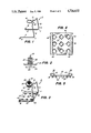
- FIG. 1 is a perspective view of a mounting bracket element according to this invention
- FIG. 2 is an elevation view of a fastener element
- FIG. 3 is a view, from the same direction as FIG. 1, of the combined base plate, mounting bracket, and fastener assembly;
- FIG. 4 is a top view of a base plate
- FIG. 5 is an end view of the base plate of FIG. 4;
- FIG. 6 is a top view of another form of mounting bracket
- FIG. 7 is an edge view of the bracket of FIG. 6.
- FIGS. 8-11 are perspective, top, and sectional views respectively of another form of base plate -- FIG. 10 being a section along the line 10--10 and FIG. 11 being a section along the line 11--11 of FIG. 9.
- the mounting bracket member 4 of this invention is shown in perspective view.
- the mounting bracket 4 includes a pair of generally parallel feet 6; a pair of generally parallel legs 8, one extending upward from each of the feet; and a yoke 10 joining the two legs 8, the yoke extending in a generally transverse plane over the feet 6.
- the plane of yoke 10 may or may not be parallel with the plane of the feet 6.
- the central portion of the yoke 10 includes a relatively narrow spring notch 12 and a relatively larger collar 14 into which a fastener such as that shown in FIG. 2 is snapped.
- the feet 6 are generally parallel so as to lie on base plate 30 (FIG. 3) which in turn lies on the back surface of a panel. Feet 6 terminate in oppositely extending tips 16 which are adapted to snap into engagement with mating apertures provided for the purpose on the edges of base plate 30.
- the mounting bracket 4 is formed of steel wire for strength and resilience, adapting it for snap engagement with base plate 30.
- Fastener 18 of the type known as a "Christmas tree" fastener is shown.
- Fastener 18 includes a central elongated body 20, a neck portion 22 defined by a pair of flanges 24, and a plurality of radial disk-like elements 26 spaced along the body 20.
- Fastener 18 is preferably formed of a plastic material.
- FIG. 3 the fastener 18 and mounting bracket 4 are shown joined by the snap-fit engagement of fastener 18 within the notch 12 and collar 14. The mounting bracket 4 is in turn snap-fit onto the base plate 30.
- FIGS. 4 and 5 show top and end views of base plate 30.
- Base plate 30 is a substantially flat metal plate having apertures 32 stamped through it, these stamped-out apertures forming barbs or "rosettes” 34 on the underside of the plate. These barbs are effective, when the plate 30 is pressed or formed onto the backside of a panel, to fasten the plate to the panel by substantial gripping action.
- Two of the parallel edges 36 of the plate 30 are upwardly inturned to form parallel longitudinal edge channels 38.
- a lateral tip hole 40 is formed near the upper end (FIG. 4) of each edge channel 38. At the lower end of each channel, the tip of each edge 36 is bent inward to form a tab 42.
- the mounting bracket 4 is shown in snap-fit engagement with the base plate 30.
- the legs and feet of bracket 4 are resiliently pressed together and the tips 16 and feet 6 of the bracket placed respectively in the tip holes 40 and edge channels 38 of the base plate.
- the heel portion 7 of each foot 6 abuts against a tab 42 to help lock the feet 6 in place within the edge channels.
- the fastener 18, mounted on the mounting bracket 4, is only one example among several types of fastener elements that might be mounted upon bracket 4. In addition to the fastener 18 as shown, there are numerous other types; and it is contemplated that the mounting bracket of this invention should accomodate such others.
- the mounting bracket 4 provides the base upon which the fastener 18 stands.
- the space between the plane of the bracket feet 6 and the yoke 10 is roughly the stand-off spacing provided by the bracket.
- a wide range of stand-off spacings, to accommodate the varying contours of the panels and structures between which they are mounted, is provided by using mounting brackets of various heights, i.e. leg dimensions.
- the bracket lends itself to production of such a variety of sizes because it is formed or bent from wire which is relatively easy to work.
- the plane of the yoke 10 may or may not be parallel with the plane of the feet 6.
- the bracket can easily be formed so that the plane of the yoke is inclined relative to that of the feet for mounting between a support structure and panel which are not parallel.
- the legs 8 can be of equal length as shown, and the plane of the yoke 10 can be inclined at other than 90° from legs 8. Also, legs 8 might be of uneven length so that the plane of yoke 10 is inclined toward one of the legs.
- FIGS. 6 and 7 show another form of mounting bracket, bracket 50 including feet 6 and tips 16 like bracket 4.
- the rest of bracket 50 is formed of legs 52 extending outwardly from the plane of the feet 6, joining at a yoke 54.
- Bracket 50 in this form can spring clip with a support structure or an adjacent panel, by means of its curved shape, as shown in FIG. 7.
- Bracket 50 may also be made of spring steel to add resilience and strength to its clipping action.
- FIGS. 8-11 show perspective, top, and sectional views of another form of base plate 60.
- Base plate 60 is a substantially flat plate of a plastic material having a plurality of stipples or raised points 62 on its underside to provide as many point contacts for joining or sonic welding of the base plate 60 onto the back side of a panel (these raised points 62 on the underside appear as dimples or recesses 64 in the top side as suggested in FIG. 9).
- Two of the parallel edges 66 of the plate 60 are upwardly inturned to form parallel longitudinal edge channels 68.
- a lateral tip hole 70 is formed near the upper end (FIG. 9) of each edge channel 68.
- the edges 66 are inturned slightly more at the lower end (FIG. 11) than at the upper end (FIG. 10).
Landscapes
- Engineering & Computer Science (AREA)
- General Engineering & Computer Science (AREA)
- Mechanical Engineering (AREA)
- Connection Of Plates (AREA)
Abstract
Description
Claims (23)
Priority Applications (2)
| Application Number | Priority Date | Filing Date | Title |
|---|---|---|---|
| US07/021,127 US4716632A (en) | 1987-03-03 | 1987-03-03 | Panel mounting fastener system |
| CA000560332A CA1293286C (en) | 1987-03-03 | 1988-03-02 | Panel mounting fastener system |
Applications Claiming Priority (1)
| Application Number | Priority Date | Filing Date | Title |
|---|---|---|---|
| US07/021,127 US4716632A (en) | 1987-03-03 | 1987-03-03 | Panel mounting fastener system |
Publications (1)
| Publication Number | Publication Date |
|---|---|
| US4716632A true US4716632A (en) | 1988-01-05 |
Family
ID=21802486
Family Applications (1)
| Application Number | Title | Priority Date | Filing Date |
|---|---|---|---|
| US07/021,127 Expired - Fee Related US4716632A (en) | 1987-03-03 | 1987-03-03 | Panel mounting fastener system |
Country Status (2)
| Country | Link |
|---|---|
| US (1) | US4716632A (en) |
| CA (1) | CA1293286C (en) |
Cited By (15)
| Publication number | Priority date | Publication date | Assignee | Title |
|---|---|---|---|---|
| WO1992004755A1 (en) * | 1990-09-06 | 1992-03-19 | Swifts Of Scarborough Limited | Cable tray systems and connecting devices therefor |
| US5704100A (en) * | 1996-03-01 | 1998-01-06 | Federal-Hoffman, Inc. | Retaining clip system |
| US6186256B1 (en) * | 1999-02-05 | 2001-02-13 | Mattel, Inc. | Battery retaining system for a children's ride-on vehicle |
| US6347679B1 (en) | 2000-11-09 | 2002-02-19 | Mattel, Inc. | Battery retaining system for children's ride-on vehicles |
| US6488437B1 (en) | 2000-09-11 | 2002-12-03 | Emery Jensen | Anchor plate |
| US6508322B2 (en) | 2000-11-09 | 2003-01-21 | Mattel, Inc. | Battery retaining system for children's ride-on vehicles |
| US20040148898A1 (en) * | 2000-05-01 | 2004-08-05 | Hick Robert Mainland | Weather strips |
| US20050056473A1 (en) * | 2003-09-11 | 2005-03-17 | Damon Daniel J. | Battery retainer assembly for children's ride-on vehicles |
| US20050056474A1 (en) * | 2003-09-11 | 2005-03-17 | Damon Daniel J. | Battery retainer assembly for children's ride-on vehicles |
| US20080236087A1 (en) * | 2001-09-07 | 2008-10-02 | Nu-Lok Roofing Systems Pty Ltd. | Weather strips |
| DE102007059271B3 (en) * | 2007-12-08 | 2009-05-07 | Jürgens, Joachim | System of spacer plates for equalizing assembly tolerances comprises one or two right-angled edges on each of at least one outer edge to form a uniform support even outside of the viewing region |
| US20110162564A1 (en) * | 2010-01-05 | 2011-07-07 | Heim Jeffrey R | System, method and apparatus for securing valuables |
| US20150000571A1 (en) * | 2013-06-27 | 2015-01-01 | Adie, LLC | Portable lock box |
| US8931422B2 (en) | 2010-01-05 | 2015-01-13 | Jeffrey R. Heim | System, method and apparatus for securing valuables |
| US9459074B2 (en) | 2010-01-05 | 2016-10-04 | Jeffrey R. Heim | System, method and apparatus for securing valuables |
Citations (12)
| Publication number | Priority date | Publication date | Assignee | Title |
|---|---|---|---|---|
| US1621720A (en) * | 1926-09-15 | 1927-03-22 | George H Harper | Table-cover holder |
| US1929590A (en) * | 1932-05-31 | 1933-10-10 | Edwin G Krentler | Automobile body inside panel fastener |
| US2037301A (en) * | 1930-11-28 | 1936-04-14 | Briggs Mfg Co | Fastener for trimming material |
| US2123527A (en) * | 1937-09-15 | 1938-07-12 | Magna Products Corp | Device for attaching license plates |
| US2198186A (en) * | 1937-07-09 | 1940-04-23 | Tinnerman Products Inc | Clip for moldings and the like |
| US2961723A (en) * | 1957-12-06 | 1960-11-29 | Illinois Tool Works | Molding clip |
| US3047920A (en) * | 1960-04-18 | 1962-08-07 | Stanley Works | Fastener |
| US3132727A (en) * | 1950-09-16 | 1964-05-12 | Automotive Rubber Company Inc | Spring retainer and seal |
| US3251105A (en) * | 1964-12-11 | 1966-05-17 | Penna Rose M La | Pop molding clip |
| US3254382A (en) * | 1963-11-29 | 1966-06-07 | Marion V Clark | Molding clip |
| JPS60191851A (en) * | 1984-11-02 | 1985-09-30 | Toyoda Gosei Co Ltd | Method of attaching protector molding |
| EP0170264A2 (en) * | 1984-07-30 | 1986-02-05 | Voplex Corporation | Retainer for molded panel |
-
1987
- 1987-03-03 US US07/021,127 patent/US4716632A/en not_active Expired - Fee Related
-
1988
- 1988-03-02 CA CA000560332A patent/CA1293286C/en not_active Expired - Fee Related
Patent Citations (12)
| Publication number | Priority date | Publication date | Assignee | Title |
|---|---|---|---|---|
| US1621720A (en) * | 1926-09-15 | 1927-03-22 | George H Harper | Table-cover holder |
| US2037301A (en) * | 1930-11-28 | 1936-04-14 | Briggs Mfg Co | Fastener for trimming material |
| US1929590A (en) * | 1932-05-31 | 1933-10-10 | Edwin G Krentler | Automobile body inside panel fastener |
| US2198186A (en) * | 1937-07-09 | 1940-04-23 | Tinnerman Products Inc | Clip for moldings and the like |
| US2123527A (en) * | 1937-09-15 | 1938-07-12 | Magna Products Corp | Device for attaching license plates |
| US3132727A (en) * | 1950-09-16 | 1964-05-12 | Automotive Rubber Company Inc | Spring retainer and seal |
| US2961723A (en) * | 1957-12-06 | 1960-11-29 | Illinois Tool Works | Molding clip |
| US3047920A (en) * | 1960-04-18 | 1962-08-07 | Stanley Works | Fastener |
| US3254382A (en) * | 1963-11-29 | 1966-06-07 | Marion V Clark | Molding clip |
| US3251105A (en) * | 1964-12-11 | 1966-05-17 | Penna Rose M La | Pop molding clip |
| EP0170264A2 (en) * | 1984-07-30 | 1986-02-05 | Voplex Corporation | Retainer for molded panel |
| JPS60191851A (en) * | 1984-11-02 | 1985-09-30 | Toyoda Gosei Co Ltd | Method of attaching protector molding |
Cited By (22)
| Publication number | Priority date | Publication date | Assignee | Title |
|---|---|---|---|---|
| WO1992004755A1 (en) * | 1990-09-06 | 1992-03-19 | Swifts Of Scarborough Limited | Cable tray systems and connecting devices therefor |
| US5704100A (en) * | 1996-03-01 | 1998-01-06 | Federal-Hoffman, Inc. | Retaining clip system |
| US6186256B1 (en) * | 1999-02-05 | 2001-02-13 | Mattel, Inc. | Battery retaining system for a children's ride-on vehicle |
| US20040148898A1 (en) * | 2000-05-01 | 2004-08-05 | Hick Robert Mainland | Weather strips |
| US7444790B2 (en) * | 2000-05-01 | 2008-11-04 | Nu-Lok Roofing Systems Pty, Ltd. | Weather strips |
| US6488437B1 (en) | 2000-09-11 | 2002-12-03 | Emery Jensen | Anchor plate |
| US6347679B1 (en) | 2000-11-09 | 2002-02-19 | Mattel, Inc. | Battery retaining system for children's ride-on vehicles |
| US6508322B2 (en) | 2000-11-09 | 2003-01-21 | Mattel, Inc. | Battery retaining system for children's ride-on vehicles |
| US20080236087A1 (en) * | 2001-09-07 | 2008-10-02 | Nu-Lok Roofing Systems Pty Ltd. | Weather strips |
| US7007767B2 (en) | 2003-09-11 | 2006-03-07 | Mattel, Inc. | Battery retainer assembly for children's ride-on vehicles |
| US6973987B2 (en) | 2003-09-11 | 2005-12-13 | Mattel, Inc. | Battery retainer assembly for children's ride-on vehicles |
| US20050056474A1 (en) * | 2003-09-11 | 2005-03-17 | Damon Daniel J. | Battery retainer assembly for children's ride-on vehicles |
| US20050056473A1 (en) * | 2003-09-11 | 2005-03-17 | Damon Daniel J. | Battery retainer assembly for children's ride-on vehicles |
| DE102007059271B3 (en) * | 2007-12-08 | 2009-05-07 | Jürgens, Joachim | System of spacer plates for equalizing assembly tolerances comprises one or two right-angled edges on each of at least one outer edge to form a uniform support even outside of the viewing region |
| US20110162564A1 (en) * | 2010-01-05 | 2011-07-07 | Heim Jeffrey R | System, method and apparatus for securing valuables |
| US8201426B2 (en) * | 2010-01-05 | 2012-06-19 | Heim Jeffrey R | System, method and apparatus for securing valuables |
| US8327777B2 (en) | 2010-01-05 | 2012-12-11 | Heim Jeffrey R | System, method and apparatus for securing valuables |
| US8534206B2 (en) | 2010-01-05 | 2013-09-17 | Jeffrey R. Heim | Bedding mounting system for a safe |
| US8770116B2 (en) | 2010-01-05 | 2014-07-08 | Jeffrey R. Heim | System, method and apparatus for securing valuables |
| US8931422B2 (en) | 2010-01-05 | 2015-01-13 | Jeffrey R. Heim | System, method and apparatus for securing valuables |
| US9459074B2 (en) | 2010-01-05 | 2016-10-04 | Jeffrey R. Heim | System, method and apparatus for securing valuables |
| US20150000571A1 (en) * | 2013-06-27 | 2015-01-01 | Adie, LLC | Portable lock box |
Also Published As
| Publication number | Publication date |
|---|---|
| CA1293286C (en) | 1991-12-17 |
Similar Documents
| Publication | Publication Date | Title |
|---|---|---|
| US4716632A (en) | Panel mounting fastener system | |
| US20050271492A1 (en) | Sheet metal fastening clip | |
| US4379536A (en) | Means for retaining a rod-shaped material | |
| US3680272A (en) | Structural assembly and clip | |
| US6398174B1 (en) | Receptacle with adjustable hanging bracket assembly | |
| US2712917A (en) | Cable clip or the like | |
| US4205815A (en) | Shelf bracket, shelf bracket-stud combination and shelf bracket-clip combination | |
| JPH0339688B2 (en) | ||
| JPS6123127Y2 (en) | ||
| KR102026241B1 (en) | Clip for perimeter trim | |
| US9850934B2 (en) | Self-reinforcing clip | |
| US3262662A (en) | Cable fastener | |
| US4779313A (en) | Retainer for molded panel | |
| US2723432A (en) | Clips for cables, conduits and the like | |
| US20180334803A1 (en) | Linear metal ceiling components | |
| US20040049894A1 (en) | Sheet metal fastening clip | |
| US20040244156A1 (en) | Sheet metal fastening clip | |
| JP3006114U (en) | Coupling clasp and drawer with coupling clasp | |
| US20040031889A1 (en) | Suspension device | |
| GB2149829A (en) | Improvements in or relating to a panel assembly | |
| EP0180836A1 (en) | Holder | |
| US4494346A (en) | Ceiling system and panel-securing device therefor | |
| JP2814103B2 (en) | Quick release fastener receptacle | |
| US2245375A (en) | Clip | |
| US4385858A (en) | Attachment clip |
Legal Events
| Date | Code | Title | Description |
|---|---|---|---|
| AS | Assignment |
Owner name: VOPLEX CORPORATION, 1100 PITTSFORD-VICTOR ROAD, PI Free format text: ASSIGNMENT OF ASSIGNORS INTEREST.;ASSIGNOR:PERL, UWE W.;REEL/FRAME:004797/0487 Effective date: 19871130 Owner name: VOPLEX CORPORATION, 1100 PITTSFORD-VICTOR ROAD, PI Free format text: ASSIGNMENT OF ASSIGNORS INTEREST;ASSIGNOR:PERL, UWE W.;REEL/FRAME:004797/0487 Effective date: 19871130 |
|
| FPAY | Fee payment |
Year of fee payment: 4 |
|
| REMI | Maintenance fee reminder mailed | ||
| LAPS | Lapse for failure to pay maintenance fees | ||
| AS | Assignment |
Owner name: BANKERS TRUST COMPANY, NEW YORK Free format text: ASSIGNMENT OF SECURITY INTEREST;ASSIGNOR:CAMBRIDGE INDUSTRIES, INC.;REEL/FRAME:007854/0613 Effective date: 19951117 |
|
| FP | Expired due to failure to pay maintenance fee |
Effective date: 19960110 |
|
| AS | Assignment |
Owner name: BANK OF AMERICA, N.A., CALIFORNIA Free format text: ASSIGNMENT OF SECURITY INTEREST;ASSIGNOR:CAMBRIDGE ACQUISITION CORP.;REEL/FRAME:011149/0335 Effective date: 20000714 |
|
| AS | Assignment |
Owner name: CAMBRIDGE INDUSTRIES, INC., MICHIGAN Free format text: RELEASE OF SECURITY INTEREST;ASSIGNOR:BANKERS TRUST COMPANY;REEL/FRAME:011511/0860 Effective date: 20000425 |
|
| STCH | Information on status: patent discontinuation |
Free format text: PATENT EXPIRED DUE TO NONPAYMENT OF MAINTENANCE FEES UNDER 37 CFR 1.362 |