US471197A - Gear-shifting mechanism for conveyers for harvesters - Google Patents
Gear-shifting mechanism for conveyers for harvesters Download PDFInfo
- Publication number
- US471197A US471197A US471197DA US471197A US 471197 A US471197 A US 471197A US 471197D A US471197D A US 471197DA US 471197 A US471197 A US 471197A
- Authority
- US
- United States
- Prior art keywords
- bevel
- bearing
- cams
- pinion
- pivoted
- Prior art date
- Legal status (The legal status is an assumption and is not a legal conclusion. Google has not performed a legal analysis and makes no representation as to the accuracy of the status listed.)
- Expired - Lifetime
Links
- 241001124569 Lycaenidae Species 0.000 title description 9
- 238000010276 construction Methods 0.000 description 3
- 241000758789 Juglans Species 0.000 description 2
- 235000009496 Juglans regia Nutrition 0.000 description 2
- 235000020234 walnut Nutrition 0.000 description 2
- 239000011230 binding agent Substances 0.000 description 1
- 230000001105 regulatory effect Effects 0.000 description 1
- 230000000284 resting effect Effects 0.000 description 1
Images

Classifications
-
- F—MECHANICAL ENGINEERING; LIGHTING; HEATING; WEAPONS; BLASTING
- F16—ENGINEERING ELEMENTS AND UNITS; GENERAL MEASURES FOR PRODUCING AND MAINTAINING EFFECTIVE FUNCTIONING OF MACHINES OR INSTALLATIONS; THERMAL INSULATION IN GENERAL
- F16H—GEARING
- F16H19/00—Gearings comprising essentially only toothed gears or friction members and not capable of conveying indefinitely-continuing rotary motion
- F16H19/02—Gearings comprising essentially only toothed gears or friction members and not capable of conveying indefinitely-continuing rotary motion for interconverting rotary or oscillating motion and reciprocating motion
- F16H19/06—Gearings comprising essentially only toothed gears or friction members and not capable of conveying indefinitely-continuing rotary motion for interconverting rotary or oscillating motion and reciprocating motion comprising flexible members, e.g. an endless flexible member
-
- Y—GENERAL TAGGING OF NEW TECHNOLOGICAL DEVELOPMENTS; GENERAL TAGGING OF CROSS-SECTIONAL TECHNOLOGIES SPANNING OVER SEVERAL SECTIONS OF THE IPC; TECHNICAL SUBJECTS COVERED BY FORMER USPC CROSS-REFERENCE ART COLLECTIONS [XRACs] AND DIGESTS
- Y10—TECHNICAL SUBJECTS COVERED BY FORMER USPC
- Y10T—TECHNICAL SUBJECTS COVERED BY FORMER US CLASSIFICATION
- Y10T74/00—Machine element or mechanism
- Y10T74/18—Mechanical movements
- Y10T74/18056—Rotary to or from reciprocating or oscillating
- Y10T74/18152—Belt or chain carried member
Definitions
- This invention relates to an improvemen in a gear-shifting mechanism for a reciprocating conveyer for harvesters and binders.
- the object of this invention is to secure compactness and efficiency in the gear-shifting mechanism and promote simplicity and cheapness in the construction in such mechanism.
- My invention consists in the construction and combination of parts, as will be hereinafter described and claimed.
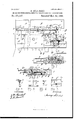
- Figure 1 is a plan View of a harvester-platform provided with my improvement.
- the upper plate is partly broken away, so as to show the mechanism below.
- Fig. 2 is a front view of the gearing and the inner portion of the platform with the finger-bar removed.
- Fig. 3 is a stubble end view of Fig. 1.
- Figs. 4, 5, 6, and 7 are detail Views of parts of the mechanism.
- Fig. 8 is a sectional view on line 1 1, Fig. 1, the strip a and the sprocket-wheel beyond the sectionline being shown in full lines.
- Fig. 9 is an enlarged side view of the cam j. 10 is an edge view of the serrated bevel-pinion, and
- Fig. 11 is a plan view of the rear or serrated side of the said bevel-pinion.
- A designates the upper plate of the platform, and A the lower plate.
- 13 designates the finger-bar, provided with the usual guards B and a shoe B.
- a and a are strips forming walls for the passage of the conveyor 1), the strip a forming the rear sill of the platform. Said strips a, a, and a are of proper width to provide room between the plate A and A for the mechanism hereinafter described.
- the plates A and A are secured to the finger-bar and the strips to, a, and a A slot 1) is left in the upper plate A.
- the strips a and a are discontinued near the stubble end of the platform to provide room for the shaft f.
- the strip a is out down at P and at P for the operation of the levers P and n.
- the finger-bar B is provided with avertical flange B near its stubble end to meet the plate A.
- Said plate Avis slightly elevated near the stubble end of the platform to provide room for the gearing beneath it.
- b is the ordinary grain-board, secured to the plates A and A and the finger-bar B in any well-known manner.
- f designates a shaft located near the stubble end of the platform and journaled with its rear end in a pivoted bearing J and with its front end in a movable bearing h and provided with a sprocket-wheeli near the center of the slot 1) and adjacent the pivoted bearing J, a collar J adjacent the rear side of the pivoted bearing J, a bevel-pinion f on its front end adjacent the front side of the movable bearing 72, and a collar J adjacent the rear side of the movable bearing h, thus preventing any rearward or forward movement of the movable bearing h.
- f designates a shaft provided with a hearing f secured to the finger-bar B in line with the pivoted bearing J.
- Bevel-pinions f and f are secured to the shaft f adjacent each side of the bearing f and in position for the bevel-pinion f to be engaged or disengaged therewith.
- h designates a movable bearing, prevented from moving, when not so desired, by the spring h, which is secured to the block if and of proper length to extend over the movable bearing h.
- Said block W is secured to the plate A and of proper length to provide a support for the movable bearing h.
- Said movable bearing 77. is constructed about as shown in Fig. 7, which shows a plan and a front view of same.
- the bearing is provided with a perforation h to receive the shaft f and with the downward projections k hiadapted to rest properly on the blockh and studs 71 h project forward from near the ends of the bearing, as shown, of proper length to receive the conveyer nears the stubble end of its the cams j and j Said cams j and j are pivoted with their lower ends to the studs h h and their other ends project upward and are connected together by the bar j.
- j j are anti-friction rollers rotating on studs j j secured in the upper ends of the cams j and j. the barj to the camsj and j.
- Fig. 4 is shown an enlarged edge view of one of the cams provided with the anti-friction roller f, the cam j being lightly serrated j and the rear side of the bevel-pinion f also being serrated f, as shown in Figs. 10 and 11, to prevent the cam j from disengaging with said bevel-pinion when not so desired.
- the bar j is provided with a stud ,7' near its center.
- n designates a lever pivotally secured to the stud 9' on the bar j" and pivoted on a pin 02 which extends with its upper end through the plate A and with the lower end through the finger-bar B, adjacent the vertical flange B and on line with the pivoted bearing J.
- the front end n of said lever '21 is provided with a draw-rod 01 which is extended to the operators seat. (Not shown in the drawings.)
- the other end of said lever projects rearward into the passage-way of the conveyer b, and is slightly curved grainward, as shown in Fig. 1, and connected to the lever P by the rod P.
- Said lever P is preferably pivot-ed at its front end to the plate A and projects toward the rear with its rear end in the passage-way of the con veyer.
- a proper Said studs j also pivotally connect distance apart and provided with set-screws t t to regulate the limit of movement of the 1 movable bearing It, thus regulating the mesh 1 of the bevel-pinion f with the bevel-pinions P and P are brackets secured to the strip 1 the grain end of the platform.
- Said sprocket- 1 wheel is secured near the center of the slot 1) on a shaft 71, which has its bearings in the strips a and a.
- the operation is as follows, viz: The shaft f receives its movement from gearing of the harvester, (not shown,) and is rotated in the direction shown by the arrow in Fig. 3. Vhen the operator desires to start the conveyer, he draws the draw-rod 01 thus shifting the rear end of lever n and the upper end of the cams jj grainward, thus engaging the cam j and anti-friction roller against the bevel-pinion f gwhich forces the lower end of the cam and the movable bearing stubbleward, thus engaging the bevel-pinion f with the bevelpinion f thereby starting the conveyer.
- the draw-rod 01 thus shifting the rear end of lever n and the upper end of the cams jj grainward, thus engaging the cam j and anti-friction roller against the bevel-pinion f gwhich forces the lower end of the cam and the movable bearing stubbleward, thus engaging the bevel-pinion f with the bevelpinion f thereby starting the conveyer.
- a bevel-pinion secured to a shaft mounted in a bearing 7a, supported to slide on a beam or block h, said bearing being provided with studs h" h, having cams j and 7" pivoted thereto, said cams j and j pivotally connected by a bar j and provided with antifriction rollers 9' and j", said cams and antifriction rollers in position to engage or disengage with the bevel-pinions f and f for the purpose described, a lever 11, pivoted to the bar j and pivoted to the harvester-platform and provided on its forward projecting end at with a draw-rod 92 as shown, and for the purpose described.
- a bevel-pinion secured to a shaft mounted in a hearing it, supported to slide on a beam or block it, said bearing being provided with studs h h, having cams j and j pivoted thereto, said cams j and j pivotally connected by a bar j and provided with antifriction rollers fiandj, the cam j serrated for the purpose described, said cams and antifriction rollers arranged in position to engage or disengage with the bevel-pinions f and f a lever n, pivoted to the bar 3 and to the platform, as shown, extending with one end toward the rear, as shown, and a conveyer IIO moving in the platform, as shown, and for the purpose described.
- a shaft f journaled with its rear end in a pivoted bearing J and provided with a sprocket-Wheel 1', carrying a chain c" to operate the conveyer
- a movable bearing h for supporting the shaft f, said bearing being supported to slide on a block or bracket secured to the platform and provided with studs h 71*, having cams j and j pivoted to said studs h h in position to engage with the bevel-pinions f and f anti-friction rollers f and j on the upper or free ends of said cams, a bar 7' connecting said cams and provided with a stud 7' a lever n, pivoted to the stud 7' and to the frame of the machine, and a spring It, secured with one end to the platform and with its other end resting on the movable bearing h, as shown, and for the purpose described.
- a bevel-pinion secured to a shaft mounted in a bearing h, supported to slide on a block or bracket 72/ said bearing being provided with studs h 72/ having cams pivoted to said studs, anti-friction rollers on said cams, the cams and anti-friction rollers in position to engage with the rear side of the bevelpinions f and f a bar j, connecting the free end of said cam and provided with a stud 3' a lever 'n, pivoted to the stud 7' and to the frame of the machine, and lugs 15 t, secured in the block or bracket k and provided with set screws t t, as shown, and for the purpose described.
- a bevel-pinion secured to a shaft mounted in a bearing it, supported to slide on a block or bracket 71?, said bearing being provided with studs 71 h, having cams pivoted to said studs, anti-friction rollers on said cams, the cams and anti-friction rollers in position to engage or disengage with the bevelpinions f and f, a bar j, connecting the free end of said cams and provided with a stud f, a lever n, pivoted to the stud 7' and to the frame of the machine, and brackets P and P secured to the platform or to the strip a, as shown, and for the purpose described.
Landscapes
- Engineering & Computer Science (AREA)
- General Engineering & Computer Science (AREA)
- Mechanical Engineering (AREA)
- Harvesting Machines For Root Crops (AREA)
Description
(No Model.) 2 Sheets-Sheet 2. I
. G. SGHUBERT. GEAR SHII'TING'MEGHANISM FOR GONVBYERS FOR HARVESTERS.
No.. 471,197. Patented Mar. 22, 1892.
WITNESSES 1.7V VZZ/V Z 0?? m: mm vex-ans co., PHOwLy Twm, msnmcrou n c NITE STATES GEORGE SCHUBERT, OF WALNUT, TEXAS.
GEAR-SHIFTING MECHANISM FOR CONVEY ERS FOR HARVESTERS.
SPECIFICATION forming part of Letters Patent No. 471,197, dated March 22, 1892. 7
Application filed July 15, 1891. Serial No. 399,558- (No model.)
To aZZ whom it may concern:
Be it known that I, GEORGE SOHUBERT, a citizen of the United States, residing at Walnut, in the county of Bosque and State of Texas, have invented a new and useful Gear- Shifting Mechanism for Conveyors for I-Iarvesters, &c., of which the following is a specification.
This invention relates to an improvemen in a gear-shifting mechanism for a reciprocating conveyer for harvesters and binders.
The object of this invention is to secure compactness and efficiency in the gear-shifting mechanism and promote simplicity and cheapness in the construction in such mechanism.
My invention consists in the construction and combination of parts, as will be hereinafter described and claimed.
Referring to the drawings, Figure 1 is a plan View of a harvester-platform provided with my improvement. The upper plate is partly broken away, so as to show the mechanism below. Fig. 2 is a front view of the gearing and the inner portion of the platform with the finger-bar removed. Fig. 3 is a stubble end view of Fig. 1. Figs. 4, 5, 6, and 7 are detail Views of parts of the mechanism. Fig. 8 is a sectional view on line 1 1, Fig. 1, the strip a and the sprocket-wheel beyond the sectionline being shown in full lines. Fig. 9 is an enlarged side view of the cam j. 10 is an edge view of the serrated bevel-pinion, and Fig. 11 is a plan view of the rear or serrated side of the said bevel-pinion.
In the drawings, A designates the upper plate of the platform, and A the lower plate.
13 designates the finger-bar, provided with the usual guards B and a shoe B.
a and a are strips forming walls for the passage of the conveyor 1), the strip a forming the rear sill of the platform. Said strips a, a, and a are of proper width to provide room between the plate A and A for the mechanism hereinafter described. The plates A and A are secured to the finger-bar and the strips to, a, and a A slot 1) is left in the upper plate A.
b are notches formed in the inward1y-projecting edges of the plate A near each end of the platform, as shown in Fig. 1, for the op eration of the conveyor 1).
The strips a and a are discontinued near the stubble end of the platform to provide room for the shaft f. The strip a is out down at P and at P for the operation of the levers P and n. The finger-bar B is provided with avertical flange B near its stubble end to meet the plate A. Said plate Avis slightly elevated near the stubble end of the platform to provide room for the gearing beneath it.
b is the ordinary grain-board, secured to the plates A and A and the finger-bar B in any well-known manner.
f designates a shaft located near the stubble end of the platform and journaled with its rear end in a pivoted bearing J and with its front end in a movable bearing h and provided with a sprocket-wheeli near the center of the slot 1) and adjacent the pivoted bearing J, a collar J adjacent the rear side of the pivoted bearing J, a bevel-pinion f on its front end adjacent the front side of the movable bearing 72, and a collar J adjacent the rear side of the movable bearing h, thus preventing any rearward or forward movement of the movable bearing h. The pivotal bearing J rests on a block A secured to the plate A and held in position by the bolt J, extending through the plate A and the block A and screwed partly into the pivoted bear= ing J.
f designates a shaft provided with a hearing f secured to the finger-bar B in line with the pivoted bearing J. Bevel-pinions f and f are secured to the shaft f adjacent each side of the bearing f and in position for the bevel-pinion f to be engaged or disengaged therewith.
h designates a movable bearing, prevented from moving, when not so desired, by the spring h, which is secured to the block if and of proper length to extend over the movable bearing h. Said block W is secured to the plate A and of proper length to provide a support for the movable bearing h. Said movable bearing 77. is constructed about as shown in Fig. 7, which shows a plan and a front view of same. The bearing is provided with a perforation h to receive the shaft f and with the downward projections k hiadapted to rest properly on the blockh and studs 71 h project forward from near the ends of the bearing, as shown, of proper length to receive the conveyer nears the stubble end of its the cams j and j Said cams j and j are pivoted with their lower ends to the studs h h and their other ends project upward and are connected together by the bar j.
j j are anti-friction rollers rotating on studs j j secured in the upper ends of the cams j and j. the barj to the camsj and j.
In Fig. 4 is shown an enlarged edge view of one of the cams provided with the anti-friction roller f, the cam j being lightly serrated j and the rear side of the bevel-pinion f also being serrated f, as shown in Figs. 10 and 11, to prevent the cam j from disengaging with said bevel-pinion when not so desired. The bar j is provided with a stud ,7' near its center. v
n designates a lever pivotally secured to the stud 9' on the bar j" and pivoted on a pin 02 which extends with its upper end through the plate A and with the lower end through the finger-bar B, adjacent the vertical flange B and on line with the pivoted bearing J. The front end n of said lever '21 is provided with a draw-rod 01 which is extended to the operators seat. (Not shown in the drawings.) The other end of said lever projects rearward into the passage-way of the conveyer b, and is slightly curved grainward, as shown in Fig. 1, and connected to the lever P by the rod P. Said lever P is preferably pivot-ed at its front end to the plate A and projects toward the rear with its rear end in the passage-way of the con veyer.
In Fig. 2 the front end of the lever 01 is shown broken away.
If t are lugs secured in the block 71, a proper Said studs j also pivotally connect distance apart and provided with set-screws t t to regulate the limit of movement of the 1 movable bearing It, thus regulating the mesh 1 of the bevel-pinion f with the bevel-pinions P and P are brackets secured to the strip 1 the grain end of the platform. Said sprocket- 1 wheel is secured near the center of the slot 1) on a shaft 71, which has its bearings in the strips a and a.
The operation is as follows, viz: The shaft f receives its movement from gearing of the harvester, (not shown,) and is rotated in the direction shown by the arrow in Fig. 3. Vhen the operator desires to start the conveyer, he draws the draw-rod 01 thus shifting the rear end of lever n and the upper end of the cams jj grainward, thus engaging the cam j and anti-friction roller against the bevel-pinion f gwhich forces the lower end of the cam and the movable bearing stubbleward, thus engaging the bevel-pinion f with the bevelpinion f thereby starting the conveyer. As
movement it moves against the levern, shift ing it along in the same direction, or stubbleward, thereby moving the upper ends of the cams stubbleward, thus disengaging the antifriction-rollerj from the bevel-pinion f and engaging the cam j with the bevel-pinion f Said cam j being slightly serrated or notched, j will remain in engagement with the bevelpinion f until it has passed said bevel-pinion f 2 and been disengaged by the anti-friction roll 7' thus shifting the movable bearing grainward, which disengages the bevel-pinion f from the bevel-pinion f and engages it with the bevel-pinion f thereby reversing the movement of the conveyer, and as the conveyer nears the grain end of its movement it moves toward the lever P and moves it grainward, thus moving the rear end of the levern and the upper end of the cams j andj in the same directions, disengaging the antifriction roller 9' and engaging the cam j with the bevel-pinion f which forces the movable bearing stubbleward, and thus disengages the bevel-pinion f from the bevel-pinion f thus discontinuing the movement of the conveyor. The cam j, being smooth, will not shift the bearing h the entire distance stubbleward without pressure against its upper end toward the bevelpinion f received from the drawrod if, as heretofore described.
Having thus described my invention, and not wishing to be understood as confining my claims of invention to the precise form or proportion of parts herein shown and described so long as the principles of construction and mode of operation are essentially the same as that herein set forth, what I claim, and desire to secure by Letters Patent, is-
1. In a gear-shifting mechanism for harvesters, a bevel-pinion secured to a shaft mounted in a bearing 7a, supported to slide on a beam or block h, said bearing being provided with studs h" h, having cams j and 7" pivoted thereto, said cams j and j pivotally connected by a bar j and provided with antifriction rollers 9' and j", said cams and antifriction rollers in position to engage or disengage with the bevel-pinions f and f for the purpose described, a lever 11, pivoted to the bar j and pivoted to the harvester-platform and provided on its forward projecting end at with a draw-rod 92 as shown, and for the purpose described.
2. In a gear-shifting mechanism for harvesters, a bevel-pinion secured to a shaft mounted in a hearing it, supported to slide on a beam or block it, said bearing being provided with studs h h, having cams j and j pivoted thereto, said cams j and j pivotally connected by a bar j and provided with antifriction rollers fiandj, the cam j serrated for the purpose described, said cams and antifriction rollers arranged in position to engage or disengage with the bevel-pinions f and f a lever n, pivoted to the bar 3 and to the platform, as shown, extending with one end toward the rear, as shown, and a conveyer IIO moving in the platform, as shown, and for the purpose described.
3. In a gear-shifting mechanism for harvesters, a shaft f, journaled with its rear end in a pivoted bearing J and provided with a sprocket-Wheel 1', carrying a chain c" to operate the conveyer, a movable bearing h for supporting the shaft f, said bearing being supported to slide on a block or bracket secured to the platform and provided with studs h 71*, having cams j and j pivoted to said studs h h in position to engage with the bevel-pinions f and f anti-friction rollers f and j on the upper or free ends of said cams, a bar 7' connecting said cams and provided with a stud 7' a lever n, pivoted to the stud 7' and to the frame of the machine, and a spring It, secured with one end to the platform and with its other end resting on the movable bearing h, as shown, and for the purpose described.
4. In a gear-shifting mechanism for harvesters, a bevel-pinion secured to a shaft mounted in a bearing h, supported to slide on a block or bracket 72/ said bearing being provided with studs h 72/ having cams pivoted to said studs, anti-friction rollers on said cams, the cams and anti-friction rollers in position to engage with the rear side of the bevelpinions f and f a bar j, connecting the free end of said cam and provided with a stud 3' a lever 'n, pivoted to the stud 7' and to the frame of the machine, and lugs 15 t, secured in the block or bracket k and provided with set screws t t, as shown, and for the purpose described.
5. In a gear-shifting mechanism for harvesters, a bevel-pinion secured to a shaft mounted in a bearing it, supported to slide on a block or bracket 71?, said bearing being provided with studs 71 h, having cams pivoted to said studs, anti-friction rollers on said cams, the cams and anti-friction rollers in position to engage or disengage with the bevelpinions f and f, a bar j, connecting the free end of said cams and provided with a stud f, a lever n, pivoted to the stud 7' and to the frame of the machine, and brackets P and P secured to the platform or to the strip a, as shown, and for the purpose described.
GEORGE SOHUBERT.
Witnesses:
J. W. RUNDELL, S. H. RUssELL.
Publications (1)
| Publication Number | Publication Date |
|---|---|
| US471197A true US471197A (en) | 1892-03-22 |
Family
ID=2540056
Family Applications (1)
| Application Number | Title | Priority Date | Filing Date |
|---|---|---|---|
| US471197D Expired - Lifetime US471197A (en) | Gear-shifting mechanism for conveyers for harvesters |
Country Status (1)
| Country | Link |
|---|---|
| US (1) | US471197A (en) |
-
0
- US US471197D patent/US471197A/en not_active Expired - Lifetime
Similar Documents
| Publication | Publication Date | Title |
|---|---|---|
| US833456A (en) | Delivery mechanism for beet-harvesters and the like. | |
| US395493A (en) | Cutting mechanism for harvesters | |
| US481202A (en) | Gear-shifting mechanism for harvesters | |
| US475423A (en) | Grain-conveyer for binders | |
| US632269A (en) | Corn-topper. | |
| US211862A (en) | Improvement in harvesting-machines | |
| US415123A (en) | Grain binder | |
| US493530A (en) | Self-binding harvester | |
| US486900A (en) | Conveyer-gearing for harvesters | |
| US223812A (en) | Harvester | |
| US429311A (en) | Corn-harvester | |
| US326694A (en) | Joseph yan de water | |
| US771204A (en) | Straw-feeding machine. | |
| US564280A (en) | Band-cutter and feeder | |
| US588752A (en) | Machine for exterminating insects | |
| US1261813A (en) | Thresher. | |
| US216706A (en) | Improvement in harvester reel and dropper | |
| US319553A (en) | Straw-stacker | |
| US285730A (en) | Harvesting-machine | |
| US434494A (en) | Harvester | |
| US470213A (en) | Grain-conveyer for binders | |
| US183730A (en) | Improvement in harvesters | |
| US128564A (en) | Improvement in harvester-droppers | |
| US256477A (en) | Harvester-frame | |
| US420429A (en) | baker |