US471037A - Shuttle-actuating mechanism for sewing-machines - Google Patents
Shuttle-actuating mechanism for sewing-machines Download PDFInfo
- Publication number
- US471037A US471037A US471037DA US471037A US 471037 A US471037 A US 471037A US 471037D A US471037D A US 471037DA US 471037 A US471037 A US 471037A
- Authority
- US
- United States
- Prior art keywords
- gear
- pins
- wheel
- sewing
- shuttle
- Prior art date
- Legal status (The legal status is an assumption and is not a legal conclusion. Google has not performed a legal analysis and makes no representation as to the accuracy of the status listed.)
- Expired - Lifetime
Links
Images

Classifications
-
- D—TEXTILES; PAPER
- D05—SEWING; EMBROIDERING; TUFTING
- D05B—SEWING
- D05B3/00—Sewing apparatus or machines with mechanism for lateral movement of the needle or the work or both for making ornamental pattern seams, for sewing buttonholes, for reinforcing openings or for fastening articles, e.g. buttons, by sewing
- D05B3/02—Sewing apparatus or machines with mechanism for lateral movement of the needle or the work or both for making ornamental pattern seams, for sewing buttonholes, for reinforcing openings or for fastening articles, e.g. buttons, by sewing with mechanisms for needle-bar movement
Definitions
- This invention relates to sewing-machines.
- the object of the invention is to produce a mechanism for imparting to the loop-taker of a sewing-machine an intermittent movement, whereby a rotary motion will be imparted to the loop-taker to carry the loop of the needlethread when presented to the loop-taker and to stop the same when a loop taken by the loop-taker is being drawn up into the cloth, the cessation of movement being so timed as to allow the forward movement of the cloth and the operation of the feed during such cessation.
- the invention consists, essentially, in a sewing-machine comprising a driving-shaft provided with a gearwheel, an independent shaft mounted adjacent to the main shaft and provided with a gear-wheel meshing with that on the main shaft of the machine, a second gear-wheel loosely mounted on the independent shaft and gearing with the loop-taker of the machine, and two sliding pins, one mounted on the frame of the machine and the other carried by a wheelinterposed between the gear-wheels on the independent shaft and revolving with the shaft, and calms whereby the pins are alternately brought into contact with and drawn from the loose gear-wheel.
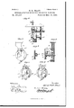
- Figure 1 is an end elevation of a sewing-machine containing my invention.
- Fig. 2 is a side elevation of the shuttle and of the parts moving the same containing my invention.
- Fig. 3 is a detail view of a supporting device for the driving and stopping mechanism.
- Fig. t is a View in side elevation of a wheel having a cam-groove, whereby the pins of the stopping mechanism are operated.
- Fig. 5 is a view, partly in section, showing the means for accomplishing the stopping and starting of the shuttle.
- Fig. 6 is a view similar to Fig. 3 with the pin-operating wheel in position, with the inner pins engaged and the outer pins free; and
- Fig. 7 is a similar view with the outer pins engaged and the inner pins free.
- A represents the main driving-shaft of the machine, on which is placed a belt or other wheel, (not shown,) which receives motion from any suitable source, such as a treadle, motor, or the like. Motion from the driving-shaft is communicated to the needle-bar and to the shuttle in any suitable wellknown way to cause two reciprocations of the needle-bar to each complete revolution of the loop-taker.
- a large gearwheel B of suitable size and fixed upon the driving-shaft back of the loop-taker, has at each side of it and supported in hangers b on shafts b gear-wheels B of one-half the diameter of the gear-wheel B, and meshing with this wheel, while mounted loosely on the outer ends of the shafts 12 are gear-wheels B of the same diameter as the loop-taker.- Interposed between each of the gear-wheels B and a gearwheel B is the mechanism whereby the gearwheels B are given motion from the shafts b and are stopped twice during each revolution of the shaft.
- This mechanism comprises a wheel 0, fixed upon the shaft b and carrying on its inner face a rigid pin, upon which slides a plate 0 carrying a pin 0 which is capable of sliding through a hole in the wheel C to project from the front face thereof or to be withdrawn to a position bringing its ends flush with the outer face of the Wheel.
- the upper portion of the plate 0 projects a short distance above the pin 0 and this projection enters grooves din plates D on the hangers as the wheel 0 revolves.
- the grooves 01 are so formed that the pins 0 are moved into one of the curved slots d of the gear-wheel B at the time when the needle of the machine, through suitable intermediate mechanism, is at a position to present the loop of the needle-thread carried thereby to one of the hooks of the loop-taker.
- the loop-taker of the machine is designated by the letter E. It is preferably made in the form illustrated in the drawings, decreasing in thickness from a point near its center toward its circumference, Where the thickness is so reduced as to present a small edge, and
- the periphery is provided with gearteeth meshing with those of the gear-wheels 13'.
- a sewing-machine comprising a loop-taker having peripheral engaging-gear and a driving-shaft provided with a gear-wheel, an independent shaft mounted adjacent to the main shaft and provided with a gear-wheel meshing with that on the main shaft of the machine, a second slotted gear wheel loosely mounted on the independent shaft and gearing with the 1oop-taker of the machine, and two sliding pins, one mounted on the frame of the machine and the other carried by a wheel interposed between the gear-wheels on the independent shaft and revolving with the shaft, and cams whereby the pins are alternately brought into contact with and drawn from the loose gear-wheel, substantially as described.
Landscapes
- Engineering & Computer Science (AREA)
- Textile Engineering (AREA)
- Sewing Machines And Sewing (AREA)
Description
2 SheetsSheet 1.
(No Model.)
H. R. TRAGY.. SHUTTLE AOTUATING MECHANISM FOR SEWING MACHINES. No. 471,037. Patented Mar. 15, 1892.
@llllfi witness/0o alter/mug,
35 her ai wawtoz (No Model.) 2 Sheets-Sheefi2.
H. R. TRACY. SHUTTLE AGTUATING MECHANISM FOR SEWING MACHINES.
Patented Mar. 15,1892.
witmooeo 351 11 01 attozmu areas 00., "IMO-HTML, wasuwc'rou, o 1:.
UNITED STATES PATENT Gr nch.
HARRIET RUTH TRACY, OF NEW BRIGHTON, NEW YORK SHUTTLE-ACTUATING MECHANISM FOR SEWING-MACHINES.
SPECIFICATION forming part of Letters Patent No. 471,037, dated March 15, 1892.
Application flled December 18, 1891' Serial No. 415,520. (No model.)
.To all whom it may concern:
Be it known that I, HARRIET RUTH TRACY, a citizen of the United States, residing atNew Brighton, in the county of Richmond and State of New York, have invented certain new and useful Improvements in Shuttle-Actuating Mechanism for Sewing-Machines; and I do hereby declare the following to be a full, clear, and exact description of the invention, such as will enable others skilled in the art to which it appertains to make and use the same.-
This invention relates to sewing-machines.
The object of the invention is to produce a mechanism for imparting to the loop-taker of a sewing-machine an intermittent movement, whereby a rotary motion will be imparted to the loop-taker to carry the loop of the needlethread when presented to the loop-taker and to stop the same when a loop taken by the loop-taker is being drawn up into the cloth, the cessation of movement being so timed as to allow the forward movement of the cloth and the operation of the feed during such cessation.
With these objects in view the invention consists, essentially, in a sewing-machine comprising a driving-shaft provided with a gearwheel, an independent shaft mounted adjacent to the main shaft and provided with a gear-wheel meshing with that on the main shaft of the machine, a second gear-wheel loosely mounted on the independent shaft and gearing with the loop-taker of the machine, and two sliding pins, one mounted on the frame of the machine and the other carried by a wheelinterposed between the gear-wheels on the independent shaft and revolving with the shaft, and calms whereby the pins are alternately brought into contact with and drawn from the loose gear-wheel.
In the accompanying drawings, forming a part of this specification, and in which like letters of reference indicate corresponding parts, Figure 1 is an end elevation of a sewing-machine containing my invention. Fig. 2 is a side elevation of the shuttle and of the parts moving the same containing my invention. Fig. 3 is a detail view of a supporting device for the driving and stopping mechanism. Fig. t is a View in side elevation of a wheel having a cam-groove, whereby the pins of the stopping mechanism are operated. Fig.
5 is a view, partly in section, showing the means for accomplishing the stopping and starting of the shuttle. Fig. 6 is a view similar to Fig. 3 with the pin-operating wheel in position, with the inner pins engaged and the outer pins free; and Fig. 7 is a similar view with the outer pins engaged and the inner pins free.
In the drawings, A represents the main driving-shaft of the machine, on which is placed a belt or other wheel, (not shown,) which receives motion from any suitable source, such as a treadle, motor, or the like. Motion from the driving-shaft is communicated to the needle-bar and to the shuttle in any suitable wellknown way to cause two reciprocations of the needle-bar to each complete revolution of the loop-taker.
One way of driving the loop-taker is shown in the accompanying drawings. A large gearwheel B, of suitable size and fixed upon the driving-shaft back of the loop-taker, has at each side of it and supported in hangers b on shafts b gear-wheels B of one-half the diameter of the gear-wheel B, and meshing with this wheel, while mounted loosely on the outer ends of the shafts 12 are gear-wheels B of the same diameter as the loop-taker.- Interposed between each of the gear-wheels B and a gearwheel B is the mechanism whereby the gearwheels B are given motion from the shafts b and are stopped twice during each revolution of the shaft. This mechanism comprises a wheel 0, fixed upon the shaft b and carrying on its inner face a rigid pin, upon which slides a plate 0 carrying a pin 0 which is capable of sliding through a hole in the wheel C to project from the front face thereof or to be withdrawn to a position bringing its ends flush with the outer face of the Wheel. The upper portion of the plate 0 projects a short distance above the pin 0 and this projection enters grooves din plates D on the hangers as the wheel 0 revolves. The grooves 01 are so formed that the pins 0 are moved into one of the curved slots d of the gear-wheel B at the time when the needle of the machine, through suitable intermediate mechanism, is at a position to present the loop of the needle-thread carried thereby to one of the hooks of the loop-taker. The pins 0 entering the slots (1 turn the wheel B around half a revolution,
when the pins are withdrawn by grooves similar to the grooves 61 and pass through an open space between the plates D before they are again brought into engagement with the gear-wheels B The peripheries of the wheels 0 are provided with cam-grooves c, in which rest plates 0 carrying pins 0 The plates 0 are supported on the pins 0 which are placed in such position on the hangers b as to be opposite to slots 12 in the gear-wheels B The pins receive a reciprocating motion during the operation of the machine, and the wheels C are so placed on their shafts that the pins 0 are projected into one of the slots b at the time when the pins 0 are withdrawn from the slot [1 serving to check the motion of the gear-wheels.
As additional means of checking the motion of the gear-wheels B, I provide the springseated pins 0 with their outer ends rounded, these pins being designed to enter indentations in the inner face of the gear-wheels, placed in such position as to be opposite the pins 0 when the impelling-pins are withdrawn.
The loop-taker of the machine is designated by the letter E. It is preferably made in the form illustrated in the drawings, decreasing in thickness from a point near its center toward its circumference, Where the thickness is so reduced as to present a small edge, and
the periphery is provided with gearteeth meshing with those of the gear-wheels 13'.
Having thus fully described my invention, what I claim, and desire to secure by Letters Patent, is
A sewing-machine comprising a loop-taker having peripheral engaging-gear and a driving-shaft provided with a gear-wheel, an independent shaft mounted adjacent to the main shaft and provided with a gear-wheel meshing with that on the main shaft of the machine, a second slotted gear wheel loosely mounted on the independent shaft and gearing with the 1oop-taker of the machine, and two sliding pins, one mounted on the frame of the machine and the other carried by a wheel interposed between the gear-wheels on the independent shaft and revolving with the shaft, and cams whereby the pins are alternately brought into contact with and drawn from the loose gear-wheel, substantially as described.
In testimony whereof I affix my signature in presence of two witnesses.
HARRIET RUTH TRACY.
Witnesses:
R. G. DYRENFORTH, E. II. PARRY.
Publications (1)
| Publication Number | Publication Date |
|---|---|
| US471037A true US471037A (en) | 1892-03-15 |
Family
ID=2539897
Family Applications (1)
| Application Number | Title | Priority Date | Filing Date |
|---|---|---|---|
| US471037D Expired - Lifetime US471037A (en) | Shuttle-actuating mechanism for sewing-machines |
Country Status (1)
| Country | Link |
|---|---|
| US (1) | US471037A (en) |
-
0
- US US471037D patent/US471037A/en not_active Expired - Lifetime
Similar Documents
| Publication | Publication Date | Title |
|---|---|---|
| US679511A (en) | Sewing-machine. | |
| US470796A (en) | Loop-taker and actuating mechanism therefor | |
| US287576A (en) | Sewing machine | |
| US432957A (en) | Island | |
| US2314513A (en) | Rotary take-up for sewing machines | |
| US437439A (en) | Robert h | |
| US240178A (en) | Feeding device for button-hole sewing-machines | |
| US1234773A (en) | Sewing-machine. | |
| US471035A (en) | Loop-taker for sewing-machines | |
| US627748A (en) | Hemstitch embroidering-machine. | |
| US351594A (en) | Sewing-machine | |
| US875620A (en) | Needle-actuating mechanism for sewing-machines. | |
| US727384A (en) | Feeding mechanism for sewing-machines. | |
| US225553A (en) | bebtin | |
| US372226A (en) | Machine for barring button-holes | |
| US300760A (en) | Machine for uniting looped fabrics | |
| CN115247320B (en) | Adjusting mechanism and sewing machine | |
| US1168536A (en) | Intermittent feed mechanism for sewing-machines. | |
| US493131A (en) | Shuttle-actuating mechanism for sewing-machines | |
| US432955A (en) | Sewing-machine | |
| US447253A (en) | Shuttle-actuating mechanism for sewing-machines | |
| US187822A (en) | Improvement in sewing-machines | |
| US1032621A (en) | Buttonhole-sewing machine. | |
| US875627A (en) | Looper-movement for sewing-machines. | |
| US979537A (en) | Sewing-machine. |