US4709414A - Optical fiber order wire system - Google Patents
Optical fiber order wire system Download PDFInfo
- Publication number
- US4709414A US4709414A US06/799,833 US79983385A US4709414A US 4709414 A US4709414 A US 4709414A US 79983385 A US79983385 A US 79983385A US 4709414 A US4709414 A US 4709414A
- Authority
- US
- United States
- Prior art keywords
- frequency
- optical
- output
- modulator
- transceiver
- Prior art date
- Legal status (The legal status is an assumption and is not a legal conclusion. Google has not performed a legal analysis and makes no representation as to the accuracy of the status listed.)
- Expired - Lifetime
Links
- 239000013307 optical fiber Substances 0.000 title claims abstract description 35
- 230000003287 optical effect Effects 0.000 claims abstract description 71
- 238000011144 upstream manufacturing Methods 0.000 claims abstract description 23
- 238000004891 communication Methods 0.000 claims abstract description 20
- 238000009434 installation Methods 0.000 abstract description 3
- 238000012423 maintenance Methods 0.000 abstract description 3
- 230000008929 regeneration Effects 0.000 abstract description 3
- 238000011069 regeneration method Methods 0.000 abstract description 3
- 239000000835 fiber Substances 0.000 description 15
- 230000015556 catabolic process Effects 0.000 description 3
- 238000006243 chemical reaction Methods 0.000 description 3
- 238000006731 degradation reaction Methods 0.000 description 3
- XUIMIQQOPSSXEZ-UHFFFAOYSA-N Silicon Chemical compound [Si] XUIMIQQOPSSXEZ-UHFFFAOYSA-N 0.000 description 2
- 230000000694 effects Effects 0.000 description 2
- 229910052732 germanium Inorganic materials 0.000 description 2
- GNPVGFCGXDBREM-UHFFFAOYSA-N germanium atom Chemical compound [Ge] GNPVGFCGXDBREM-UHFFFAOYSA-N 0.000 description 2
- 229910052710 silicon Inorganic materials 0.000 description 2
- 239000010703 silicon Substances 0.000 description 2
- 230000005236 sound signal Effects 0.000 description 2
- 229910000530 Gallium indium arsenide Inorganic materials 0.000 description 1
- KXNLCSXBJCPWGL-UHFFFAOYSA-N [Ga].[As].[In] Chemical compound [Ga].[As].[In] KXNLCSXBJCPWGL-UHFFFAOYSA-N 0.000 description 1
- 230000003321 amplification Effects 0.000 description 1
- 238000010586 diagram Methods 0.000 description 1
- 230000013011 mating Effects 0.000 description 1
- 238000000034 method Methods 0.000 description 1
- 238000012986 modification Methods 0.000 description 1
- 230000004048 modification Effects 0.000 description 1
- 238000003199 nucleic acid amplification method Methods 0.000 description 1
- 238000010079 rubber tapping Methods 0.000 description 1
- 238000012360 testing method Methods 0.000 description 1
Images


Classifications
-
- H—ELECTRICITY
- H04—ELECTRIC COMMUNICATION TECHNIQUE
- H04B—TRANSMISSION
- H04B10/00—Transmission systems employing electromagnetic waves other than radio-waves, e.g. infrared, visible or ultraviolet light, or employing corpuscular radiation, e.g. quantum communication
- H04B10/27—Arrangements for networking
- H04B10/278—Bus-type networks
-
- H—ELECTRICITY
- H04—ELECTRIC COMMUNICATION TECHNIQUE
- H04B—TRANSMISSION
- H04B10/00—Transmission systems employing electromagnetic waves other than radio-waves, e.g. infrared, visible or ultraviolet light, or employing corpuscular radiation, e.g. quantum communication
- H04B10/40—Transceivers
Definitions
- This invention relates to communication systems using optical fibers.
- optical fiber communication systems For the installation of optical fiber communication systems it has been proposed to use a dedicated optical fiber cable known as an order wire which can be used during installation and maintenance of the system by the installing and maintenance company to test the system. Specifically at remote sites, engineers would connect to the order wire communication sets which include microphone and earphone whereby the engineers can communicate with each other.
- order wire communication sets which include microphone and earphone whereby the engineers can communicate with each other.
- Such communication sets operate on a half-duplex principle, i.e., one party talks while the other listens and vice versa. Also, only two parties can use the system at any one time. Finally, the received signal is not regenerated so that the range between sites is limited.
- a transceiver for use with an optical fiber communication system, comprising an audio input and an audio output, laser means optically connected to a downstream link and to an upstream link of an optical fiber forming part of the communication system, optical detector means optically connected to the downstream and upstream links, encoding and drive means connected between the audio input and the laser means and arranged to encode the audio input signal into a portion encoded according to a first code and a portion encoded according to a second code, the laser means being driven by both portions, decoding means connected between the optical detector means and the audio output and arranged to recover from the upstream link signals encoded according to the first code and to recover from the downstream link signals encoded according to the second code, and signal regeneration means connected between the decoding means and the encoding means whereby recovered signals are regenerated in their originally encoded form and mixed with new signals from the audio input.
- a transceiver for use with an optical fiber communication system, comprising an audio input and an audio output, a first optical connector for connection of the transceiver to a downstream link of an optical fiber forming part of the communication system and a second optical connector for connection of the transceiver to an upstream link of the optical fiber, a first frequency modulator and a second frequency modulator both connected to the audio input, the first modulator operating at a first centre frequency f 1 and the second modulator operating at a second centre frequency f 2 , a first laser connected for modulation by the first modulator and optically connected to the first optical connector, a second laser connected for modulation by the second modulator and optically connected to the second optical connector, a first optical detector optically connected to the second optical connector and connected to a first demodulator having an output connected both to the audio output and to the first frequency modulator, a second optical detector optically connected to the first optical connector and connected to a second demodulator having an output connected
- bandpass filters are connected before the demodulators, one stopping f 2 frequencies and the other stopping f 1 frequencies.
- a transceiver for use with an optical fiber communication system, comprising an audio input and an audio output, a first optical connector for connection of the transceiver to a downstream link of an optical fiber forming part of the communication system and a second optical connector for connection of the transceiver to an upstream link of the optical fiber, a first frequency modulator and a second frequency modulator both connected to the audio input the first modulator operating at a first centre frequency f 1 and the second modulator operating at a second centre frequency f 2 , a laser connected for modulation by both the first modulator and the second modulator and optically connected to both the first optical connector and the second optical connector, a first optical detector optically connected to the second optical connector and connected through a first filter means to a first demodulator having an output connected both to the audio output and to the first frequency modulator, the first filter means being arranged to pass frequencies substantially at f 1 and stop frequencies at f 2 , a second optical detector optically connected to the first optical
- the filter means are necessary to proper operation because both f 1 and f 2 frequencies are transmitted both upstream and downstream.
- the invention also contemplates a digital, instead of an analog, system of communication, in which frequency upshifters and downshifters are used instead of the frequency modulators and demodulators and A/D and D/A converters are used as appropriate.
- FIG. 1 is a schematic view of a fiber-optic cable order-wire system according, to the invention
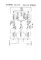
- FIGS. 2(a), (b) and (c) together constitute a view of part of the system of FIG. 1 illustrating schematically the electrical components and interconnections in the interface boxes located at each of three stations;
- FIG. 3 is a schematic view illustrating a first modified version of interface box
- FIG. 4 is a schematic view illustrating a second modified version of interface box
- FIGS. 5(a), (b) and (c) constitute a view similar to FIG. 2 but showing a modified system according to the invention
- FIGS. 6(a), (b) and (c) constitute a view similar to FIGS. 2 and 5 but illustrating a digital system according to the invention
- FIG. 7 is a schematic view illustrating the components of an interface box of a modified digital system.
- FIG. 8 is a diagram showing the arrangement of data words used in the system of FIG. 7.
- each splice enclosure includes a splice 13 comprising a first connector 14 terminating one portion of the optical fiber 11 and a second, mating connector 15, carried on the end of a fiber element 16 known as a pigtail which terminates an adjacent portion of the optical fiber 11.
- a fiber element 16 known as a pigtail which terminates an adjacent portion of the optical fiber 11.
- each interface box 17 has a connector 20 adapted to mate with connector 15 and a connector 21 on the end of a pigtail fiber 22, which connector 21 is adapted to mate with connector 14.
- FIG. 2 Three interface boxes 17 are shown schematically in FIG. 2, located at three different points along the order wire referred to as stations 1, 2 and 3.
- the handset 18 shown in FIG. 1 is illustrated in FIG. 2 as a separate microphone 24 and speaker or earphone 25.
- Microphone 24 is connected through an amplifier 26 to two adders 27 and 28 each of which also has an input connected to the audio output side via lines 29 and 30.
- the output of adder 27 is connected through a frequency modulator 31, which modulates at a first centre frequency f 1 , to a first input of an adder 32 and the output of adder 28 is connected through a frequency modulator 33, which modulates at a second centre frequency f 2 , to a second input of adder 32.
- f 1 and f 2 should not be related harmonically. In an experimental system f 1 was 48 KHz and f 2 was 75 KHz. Preferably, however, f 1 should not be less than 100 KHz and f 2 should be greater than 250 KHz.
- the output of adder 32 is connected to a laser driver 36 which is connected to drive a laser 37, typically an L.E.D.
- the laser output is connected to an optical fiber 38 which is connected by an optical coupler 39 to two further optical fibers 40 and 41.
- Optical fiber 40 is connected through an optical coupler 42 to connector 20 for connection to the upstream side of optical fiber 11 and optical fiber 41 is connected through an optical coupler 43 to connector 21 for connection to the downstream side of optical fiber 11.
- Optical couplers 42 and 43 are singlemode - singlemode couplers each formed, for example, as a fused biconical coupler made of 2 singlemode fibers.
- Optical coupler 42 also connects the upstream side of optical fiber 11 to a first input side comprising an optical fiber 47, an optical detector 48, an amplifier 49, a band pass filter 50 designed to pass frequency f 1 but not f 2 and an FM demodulator 51 the output of which is connected through an amplifier 52 to earphone 25.
- the output of demodulator 51 is also connected via line 29 to adder 27 as described above.
- optical coupler 43 connects the downstream side of optical fiber 11 to a second input side comprising an optical fiber 55, an optical detector 56, an amplifier 57, a bandpass filter 58 designed to pass frequency f 2 but not f 1 and an FM demodulator 59 the output of which is connected through the amplifier 52 to earphone 25.
- the output of demodulator is also connected via line 30 to adder 28 as described above.
- a device suitable for use as detectors 48 and 56 at a wavelength of approximately 0.8 m is a Silicon PIN (P-Instrinic-N) photodiode or a Silicon APD (Avalanche Photodiode).
- the detectors could each comprise a Germanium PIN photodiode, a Germanium APD or, because of its lower noise, a photodiode constructed from Indium Gallium Arsenide (In Ga As).
- the operation of the system will be described from the point of view of station 2.
- the signal from the speaker frequency modulates the two frequencies f 1 and f 2 and this combined signal drives laser 37.
- the optical signal Via couplers 39 and 42 the optical signal is coupled into the upstream fiber link and via couplers 39 and 43 the optical signal is coupled into the downstream fiber link.
- the optical signal is coupled by optical coupler 43 in station 1 to optical detector 56 and converted into an electrical signal which is amplified and passed to bandpass filter 58 which passes frequency f 2 but filters out f 1 .
- the filtered signal is then demodulated in demodulator 59 to drive earphone 25 via amplifier 52.
- the recovered demodulated signal also passes along line 30 to amplifier 28 and modulator 33 which regenerates the modulated centre frequency f 2 .
- Laser 37 in station 1 regenerates the optical signal with centre frequency f 2 which via couplers 39, 42 and 43 is passed both upstream and downstream. For the upstream case, the process described above is repeated.
- the optical signal at frequency f 2 from station 1 is passed through optical coupler 42 in station 2 and detected by optical detector 48.
- the resultant electrical signal is stopped by band pass filter 50 which is designed to block frequency f 2 , thus preventing feedback from station 1 to station 2.
- band pass filter 50 which is designed to block frequency f 2 , thus preventing feedback from station 1 to station 2.
- FIG. 3 When using a single laser 37 modulated by both f l and f 2 a portion of the optical signal being sent out of an interface box 17 may be returned through the optical couplers 42 and 43.
- the way in which the effect of this undesirable feedback is minimized is illustrated in FIG. 3.
- Amplifier 59 of FIG. 2 is formed as a subtractor 59' having an inverting input connected to the output of f 2 modulator 33 through a potentiometer 62. In this way a selectable fraction K of the f 2 modulated signal used to drive laser 37 is subtracted in subtractor 59' from the signal detected in optical detector 56.
- This value K can be chosen to correspond to the fraction of the outgoing signal f 1 +f 2 which is inadvertently coupled back to detector 56 by optical coupler 43.
- the signal which is being received from the downstream station at optical coupler 43 is designated f 1 '+f 2 '.
- the signal remaining is f 1 '+f 2 '+Kf 1 and so the output of the bandpass filter 58 is f 2 ' which shows that the feedback has been removed, thereby increasing the carrier-to-noise ratio and increasing the range of operation.
- amplifier 49 is replaced with subtractor 49' having an inverting input connected to the output of the f 1 modulator 31 through a potentiometer 63 so as to subtract KF 1 from the signal before it reaches bandpass filter 50.
- FIG. 4 In which most of the components and interconnections are unchanged from the FIG. 2 embodiment.
- the specific changes are that laser driver 36 and laser 37 are replaced with laser drivers 36a and 36b and lasers 37a and 37b.
- Adder 32 is dispensed with, the output of f 1 modulator 31 being connected directly to laser driver 36a, and the output of f 2 modulator 33 being connected directly to laser driver 36b.
- Optical coupler 39 is also dispensed with.
- f 1 and f 2 are not both applied to both upstream and downstream links; only f 2 is applied to the upstream link and only f 1 applied to the downstream link.
- the bandpass filters in this case are used to remove internal feedback arising from the optical couplers and are not necessary to filter out directly received f 1 or f 2 signals.
- the transceiver of the present invention permits full duplex and multi-party operation and, since the incoming signal is regenerated at each station, it removes any limits on range providing the next station is less than -25 dB away.
- FIG. 5 illustrates a variation of the system shown in FIG. 2 which is adapted to access multimode fiber in addition to a singlemode fiber.
- the difference is that the 1 ⁇ 2 singlemode optical couplers 42 and 43 of FIG. 2 are replaced with 2 ⁇ 2 multimode-singlemode couplers 42' and 43'.
- One of the inputs of coupler 42' is connected to the upstream singlemode fiber and the other input is connected to the upstream multimode fiber (not shown) by means of appropriate connectors 20 and 70, respectively.
- One of the inputs of coupler 43' is connected to the downstream singlemode fiber and the other input is connected to the downstream multimode fiber (not shown) by means of appropriate connectors 21 and 71, respectively.
- each multimode-singlemode coupler is a fused biconical coupler made of 1 singlemode and 1 multimode fiber. The remaining components may be identical to those described with reference to FIG. 2.
- FIG. 6 illustrates a digital version of the system shown in FIGS. 2 and 5.
- the principal differences are the frequency modulators 31 and 33 and frequency demodulators 51 and 59 are replaced, respectively, with frequency upshifters 73 and 74 and frequency downshifters 75 and 76.
- the laser driver 36 is replaced with an A/D converter 77 and the amplifiers 49 and 59 are replaced with D/A converters 78 and 79. It is believed that a detailed description of this digital version is unnecessary and that the operation thereof will be readily apparent to those skilled in the art particularly in the light of the foregoing description of the analog version.
- Typical values for the two shift frequencies f 1 and f 2 are 0 and 5 KHz.
- the main advantages of the digital system are that it can sustain a loss of 36 dB instead of the 25 dB loss it can endure in the analog version and the system experiences no degradation when the signal is regenerated.
- FIGS. 5 and 6 Also illustrated in FIGS. 5 and 6 are the fact that the interface boxes may be connected to the fibers either by splicing without connectors, or by means of connectors or what is termed local launch and detect. The last option involves retaining the integrity of the fiber and tapping into the fiber via diodes 80.
- FIG. 4 circuitry A digital version of the FIG. 4 circuitry is also contemplated.
- the frequency modulators and demodulators would be replaced with frequency upshifters and downshifters, and amplifiers 49 and 59 would be replaced with D/A converters.
- the difference over the FIG. 6 embodiment would be that, because two lasers are used, there would be two A/D converters (in place of the laser drivers).
- FIG. 7 The system illustrated in FIG. 7 is also a digital system but this represents a somewhat refined version of the basic digital system.
- an audio signal is digitized, each sample consisting of n bits.
- these n bits are assembled into a word 2 n bits long: bits 0 to n-1 convey data downstream in the order wire system and are called “Digital Word #1", while bits n to 2n-1 convey data upstream and are called “Digital Word #2”.
- a serial bit stream is detected by optical detector 81 and, after amplification, decoding and removal of start, stop, parity bits and other necessary additional elements by block 82, the serial bit stream is converted by serial to parallel register 83 to a sequence of parallel primary words, i.e., Digital Word #1.
- register 83 will receive a block of 2n bits comprising Digital Words #1 and #2 but Digital Word #2 is "thrown away" i.e. nothing is done with it: only Digital Word #1 is used from this register.
- the audio signal produced by microphone 86 is amplified by amplifier 87 and converted by A/D converter 88 to a sequence of parallel words each of n bits.
- a digital adder 89 sums the digitized audio from the microphone and recovered Digital Word #1 to produce bits 0 to n-1 of the word which is to be transmitted by laser 90. Bits n to 2n-1 of the word to be transmitted are obtained by summing in an adder 92 the Digital Word #2, which is recovered from the digital signal detected by detector 93 and passed through amplifying and demodulating stage 94 and serial to parallel register 95, and the digitized audio from the microphone. As with register 83 only one of the two digital words is used from register 95, in this case Digital Word #2. Words #1 and #2 are combined in a parallel to series register 96 and passed to a laser driver 97 for driving laser diode 90.
- Received Digital Words #1 and #2 are summed by adder 99, converted back to an analog signal by a D/A converter 100 and amplified by amplifier 101 for connection to earphone 102.
- This system is a full duplex, multi-party system in which regeneration of data passed downstream and upstream is entirely digital.
- the significant difference between the system of FIG. 6 and that of FIG. 7 is that the former involves conversion from digital to analog (in D/A 78) after receipt of the transmitted signal and then reconversion back to digital (in A/D 77) and such conversion in both directions may give rise to some degradation of the signal.
- the signal to be regenerated remains as a digital signal and does not, therefore, suffer any degradation as a result of conversion and reconversion.
- FIG. 7 embodiment could be modified by providing two lasers somewhat in the manner shown in FIG. 4 with appropriate modifications in circuitry.
Landscapes
- Engineering & Computer Science (AREA)
- Physics & Mathematics (AREA)
- Electromagnetism (AREA)
- Computer Networks & Wireless Communication (AREA)
- Signal Processing (AREA)
- Computing Systems (AREA)
- Optical Communication System (AREA)
- Bidirectional Digital Transmission (AREA)
- Interconnected Communication Systems, Intercoms, And Interphones (AREA)
- Monitoring And Testing Of Transmission In General (AREA)
Abstract
Description
Claims (7)
Applications Claiming Priority (2)
| Application Number | Priority Date | Filing Date | Title |
|---|---|---|---|
| CA000483730A CA1235185A (en) | 1985-06-12 | 1985-06-12 | Optical fiber order wire system |
| CA483730 | 1985-06-12 |
Publications (1)
| Publication Number | Publication Date |
|---|---|
| US4709414A true US4709414A (en) | 1987-11-24 |
Family
ID=4130689
Family Applications (1)
| Application Number | Title | Priority Date | Filing Date |
|---|---|---|---|
| US06/799,833 Expired - Lifetime US4709414A (en) | 1985-06-12 | 1985-11-20 | Optical fiber order wire system |
Country Status (6)
| Country | Link |
|---|---|
| US (1) | US4709414A (en) |
| JP (1) | JPS61285855A (en) |
| AU (1) | AU584203B2 (en) |
| CA (1) | CA1235185A (en) |
| GB (1) | GB2176363B (en) |
| NZ (1) | NZ216211A (en) |
Cited By (5)
| Publication number | Priority date | Publication date | Assignee | Title |
|---|---|---|---|---|
| US4825113A (en) * | 1986-03-03 | 1989-04-25 | Seiko Instruments Inc. | Single transmission line bidirectional optical communication system |
| US5005212A (en) * | 1989-12-12 | 1991-04-02 | At&T Bell Laboratories | Interference suppression in optical communication systems |
| US5202943A (en) * | 1991-10-04 | 1993-04-13 | International Business Machines Corporation | Optoelectronic assembly with alignment member |
| US5532864A (en) * | 1995-06-01 | 1996-07-02 | Ciena Corporation | Optical monitoring channel for wavelength division multiplexed optical communication system |
| EP0944990A1 (en) * | 1996-10-10 | 1999-09-29 | MVS Incorporated | Cellular system with optical link between mobile telephone switching office and cell sites |
Families Citing this family (6)
| Publication number | Priority date | Publication date | Assignee | Title |
|---|---|---|---|---|
| JPS63301661A (en) * | 1987-06-01 | 1988-12-08 | Sumitomo Electric Ind Ltd | Light transmitting type communication telephone |
| DE3827228A1 (en) * | 1988-08-11 | 1990-02-15 | Standard Elektrik Lorenz Ag | TRANSMITTER / RECEIVER FOR A BIDIRECTIONAL COHERENT-OPTICAL TRANSMISSION SYSTEM |
| GB8903568D0 (en) * | 1989-02-16 | 1989-04-05 | British Telecomm | Optical communications system |
| CA2067300C (en) * | 1992-04-27 | 1996-01-09 | Akira Fujisaki | Converting device using an optical fiber |
| US5729335A (en) * | 1996-08-23 | 1998-03-17 | Mcdonnell Douglas Corporation | Optical fiber monitoring apparatus and an associated method for monitoring bending or strain on an optical fiber during installation |
| US5963349A (en) * | 1997-01-27 | 1999-10-05 | Lucent Technologies Inc. | Inexpensive single-fiber bidirectional data link |
Citations (4)
| Publication number | Priority date | Publication date | Assignee | Title |
|---|---|---|---|---|
| JPS58111449A (en) * | 1981-12-24 | 1983-07-02 | Fujitsu Ten Ltd | Multiplex optical transmission system |
| US4393516A (en) * | 1979-03-09 | 1983-07-12 | Electric Power Research Institute, Inc. | Data transmission system and method |
| JPS58171138A (en) * | 1982-04-01 | 1983-10-07 | Nec Corp | Optical transmission and reception system |
| DE3436135A1 (en) * | 1983-10-03 | 1985-04-25 | Fuji Electric Co., Ltd., Kawasaki, Kanagawa | Optical data transmission loop |
Family Cites Families (3)
| Publication number | Priority date | Publication date | Assignee | Title |
|---|---|---|---|---|
| JPS6030143B2 (en) * | 1979-07-17 | 1985-07-15 | 株式会社東芝 | Call route system in distributed control exchange |
| FR2472889A1 (en) * | 1979-12-28 | 1981-07-03 | Comp Generale Electricite | OPTICAL TELEPHONY DEVICE |
| JPS5991745A (en) * | 1982-11-18 | 1984-05-26 | Yamatake Honeywell Co Ltd | Coupler for optical communication |
-
1985
- 1985-06-12 CA CA000483730A patent/CA1235185A/en not_active Expired
- 1985-11-20 US US06/799,833 patent/US4709414A/en not_active Expired - Lifetime
-
1986
- 1986-05-16 NZ NZ216211A patent/NZ216211A/en unknown
- 1986-05-21 AU AU57631/86A patent/AU584203B2/en not_active Ceased
- 1986-05-29 GB GB8613060A patent/GB2176363B/en not_active Expired
- 1986-06-09 JP JP61133604A patent/JPS61285855A/en active Pending
Patent Citations (4)
| Publication number | Priority date | Publication date | Assignee | Title |
|---|---|---|---|---|
| US4393516A (en) * | 1979-03-09 | 1983-07-12 | Electric Power Research Institute, Inc. | Data transmission system and method |
| JPS58111449A (en) * | 1981-12-24 | 1983-07-02 | Fujitsu Ten Ltd | Multiplex optical transmission system |
| JPS58171138A (en) * | 1982-04-01 | 1983-10-07 | Nec Corp | Optical transmission and reception system |
| DE3436135A1 (en) * | 1983-10-03 | 1985-04-25 | Fuji Electric Co., Ltd., Kawasaki, Kanagawa | Optical data transmission loop |
Non-Patent Citations (8)
| Title |
|---|
| Anritsu Electric Co., Ltd. Cat. No. MS98A, "Optical Portable Telephone", 1984. |
| Anritsu Electric Co., Ltd. Cat. No. MS98A, Optical Portable Telephone , 1984. * |
| Coyne Integrated Broadband Distribution International Symposium on Subscriber Loops & Services Atlanta, Ga. 20 24, Mar. 1978, pp. 44 48. * |
| Coyne-Integrated Broadband Distribution-International Symposium on Subscriber Loops & Services-Atlanta, Ga.-20-24, Mar. 1978, pp. 44-48. |
| Plantronics, Wilcom brochure, "Model T347B Fiber Optic . . . ", 1984. |
| Plantronics, Wilcom brochure, Model T347B Fiber Optic . . . , 1984. * |
| Tau Tron brochure, 5490R Voicelink Fiber Communications Set . * |
| Tau-Tron brochure, "5490R Voicelink Fiber Communications Set". |
Cited By (7)
| Publication number | Priority date | Publication date | Assignee | Title |
|---|---|---|---|---|
| US4825113A (en) * | 1986-03-03 | 1989-04-25 | Seiko Instruments Inc. | Single transmission line bidirectional optical communication system |
| US5005212A (en) * | 1989-12-12 | 1991-04-02 | At&T Bell Laboratories | Interference suppression in optical communication systems |
| US5202943A (en) * | 1991-10-04 | 1993-04-13 | International Business Machines Corporation | Optoelectronic assembly with alignment member |
| US5532864A (en) * | 1995-06-01 | 1996-07-02 | Ciena Corporation | Optical monitoring channel for wavelength division multiplexed optical communication system |
| US5798855A (en) * | 1995-06-01 | 1998-08-25 | Ciena Corporation | Optical monitoring channel for wavelength division multiplexed optical communication system |
| EP0944990A1 (en) * | 1996-10-10 | 1999-09-29 | MVS Incorporated | Cellular system with optical link between mobile telephone switching office and cell sites |
| EP0944990A4 (en) * | 1996-10-10 | 2001-07-04 | Mvs Inc | Cellular system with optical link between mobile telephone switching office and cell sites |
Also Published As
| Publication number | Publication date |
|---|---|
| CA1235185A (en) | 1988-04-12 |
| GB8613060D0 (en) | 1986-07-02 |
| GB2176363A (en) | 1986-12-17 |
| AU584203B2 (en) | 1989-05-18 |
| JPS61285855A (en) | 1986-12-16 |
| AU5763186A (en) | 1986-12-18 |
| NZ216211A (en) | 1989-04-26 |
| GB2176363B (en) | 1989-07-05 |
Similar Documents
| Publication | Publication Date | Title |
|---|---|---|
| US5995256A (en) | Method and system for managing optical subcarrier reception | |
| US4709414A (en) | Optical fiber order wire system | |
| GB2251148A (en) | Optical repeater having loop-back function | |
| EP0528225A2 (en) | Low distortion laser system for am fiber optic communication | |
| JP3188719B2 (en) | Optical transmission system | |
| JPH02230220A (en) | Light transmission system | |
| RU2138913C1 (en) | Method for signal transmission in passive optical long-distance communication system | |
| JP2000059306A (en) | Optical amplifying repeater | |
| EP1209840A2 (en) | Bidirectional optical communications which allows data recovery without first establishing timing and phase lock | |
| US5005212A (en) | Interference suppression in optical communication systems | |
| CN112769538B (en) | Secure communication system with hidden time delay signature | |
| US4499600A (en) | Supervision of transmission systems | |
| KR20010034668A (en) | WDM transmission repeater, WDM transmission system and WDM transmission method | |
| US6509984B1 (en) | Crosstalk reduction in a bidirectional optical link | |
| JP3339277B2 (en) | Optical transmission system | |
| JP3141554B2 (en) | SV / ALC signal superposition method | |
| JP2003198486A (en) | Bidirectional light transmission system, light transmitter, and light receiver | |
| JPS58188945A (en) | Subsignal transmission system | |
| EP0848514A2 (en) | Wavelength division multiplex optical transmitter capable of supressing degradation of optical SN | |
| JPH05136745A (en) | Optical transmission system | |
| JPH07154330A (en) | Optical repeater | |
| JPH1041887A (en) | Optical network system | |
| JPS6030456B2 (en) | Optical bipolar communication system | |
| JP2504166B2 (en) | Optical submarine repeater | |
| JP2000151522A (en) | Transmission link for transmitting optical signal |
Legal Events
| Date | Code | Title | Description |
|---|---|---|---|
| AS | Assignment |
Owner name: NORTHERN TELECOM LIMITED, P. O. BOX 6123, STATION Free format text: ASSIGNMENT OF ASSIGNORS INTEREST.;ASSIGNOR:BELL CANADA;REEL/FRAME:004493/0776 Effective date: 19851122 Owner name: BELL-NORTHERN RESEARCH LTD., P. O. BOX 3511, STATI Free format text: ASSIGNMENT OF ASSIGNORS INTEREST.;ASSIGNORS:SO, VINCENT C.;VELLA, PAUL J.;CLEGG, DAVID D.;AND OTHERS;REEL/FRAME:004493/0774 Effective date: 19851015 Owner name: BELL CANADA, 1050 BEAVER HALL HILL, MONTREAL, QUEB Free format text: ASSIGNMENT OF ASSIGNORS INTEREST.;ASSIGNOR:BELL-NORTHERN RESEARCH LTD.;REEL/FRAME:004493/0775 Effective date: 19851104 |
|
| STCF | Information on status: patent grant |
Free format text: PATENTED CASE |
|
| FPAY | Fee payment |
Year of fee payment: 4 |
|
| FEPP | Fee payment procedure |
Free format text: PAYOR NUMBER ASSIGNED (ORIGINAL EVENT CODE: ASPN); ENTITY STATUS OF PATENT OWNER: LARGE ENTITY |
|
| FPAY | Fee payment |
Year of fee payment: 8 |
|
| FPAY | Fee payment |
Year of fee payment: 12 |
|
| AS | Assignment |
Owner name: NORTEL NETWORKS CORPORATION, CANADA Free format text: CHANGE OF NAME;ASSIGNOR:NORTHERN TELECOM LIMITED;REEL/FRAME:010567/0001 Effective date: 19990429 |
|
| AS | Assignment |
Owner name: NORTEL NETWORKS LIMITED, CANADA Free format text: CHANGE OF NAME;ASSIGNOR:NORTEL NETWORKS CORPORATION;REEL/FRAME:011195/0706 Effective date: 20000830 Owner name: NORTEL NETWORKS LIMITED,CANADA Free format text: CHANGE OF NAME;ASSIGNOR:NORTEL NETWORKS CORPORATION;REEL/FRAME:011195/0706 Effective date: 20000830 |