US470692A - Mince-meat machine - Google Patents
Mince-meat machine Download PDFInfo
- Publication number
- US470692A US470692A US470692DA US470692A US 470692 A US470692 A US 470692A US 470692D A US470692D A US 470692DA US 470692 A US470692 A US 470692A
- Authority
- US
- United States
- Prior art keywords
- mince
- meat
- chamber
- plate
- chambers
- Prior art date
- Legal status (The legal status is an assumption and is not a legal conclusion. Google has not performed a legal analysis and makes no representation as to the accuracy of the status listed.)
- Expired - Lifetime
Links
- 239000000463 material Substances 0.000 description 15
- 238000007599 discharging Methods 0.000 description 9
- 210000003414 extremity Anatomy 0.000 description 8
- 235000013372 meat Nutrition 0.000 description 6
- 238000010276 construction Methods 0.000 description 5
- 238000004519 manufacturing process Methods 0.000 description 4
- 210000001364 upper extremity Anatomy 0.000 description 4
- 210000003141 lower extremity Anatomy 0.000 description 3
- XLYOFNOQVPJJNP-UHFFFAOYSA-N water Substances O XLYOFNOQVPJJNP-UHFFFAOYSA-N 0.000 description 3
- 238000012856 packing Methods 0.000 description 2
- 241000439007 Gaius Species 0.000 description 1
- 230000002708 enhancing effect Effects 0.000 description 1
- 238000003825 pressing Methods 0.000 description 1
- 230000001105 regulatory effect Effects 0.000 description 1
- 238000009877 rendering Methods 0.000 description 1
- 239000007787 solid Substances 0.000 description 1
- 238000003892 spreading Methods 0.000 description 1
- 238000005303 weighing Methods 0.000 description 1
Images


Classifications
-
- B—PERFORMING OPERATIONS; TRANSPORTING
- B29—WORKING OF PLASTICS; WORKING OF SUBSTANCES IN A PLASTIC STATE IN GENERAL
- B29C—SHAPING OR JOINING OF PLASTICS; SHAPING OF MATERIAL IN A PLASTIC STATE, NOT OTHERWISE PROVIDED FOR; AFTER-TREATMENT OF THE SHAPED PRODUCTS, e.g. REPAIRING
- B29C45/00—Injection moulding, i.e. forcing the required volume of moulding material through a nozzle into a closed mould; Apparatus therefor
- B29C45/17—Component parts, details or accessories; Auxiliary operations
- B29C45/26—Moulds
- B29C45/27—Sprue channels ; Runner channels or runner nozzles
- B29C45/2725—Manifolds
Definitions
- i l r 6 are respectively top plan and side elevation of said revoluble support, illustrating the same as with the outer walls of the blockforming chambers removed therefrom.
- vention furthermore consists in a carrier or yUNITED STATES PATENT Grrrcn.
- My invention relates to improvements in mince-meat machines, and has for its object the production of a simple and effective device vwhereby the mince-meat previously prepared is formed into blocks of equal size and weight, thus obviating the necessity of hand-Weighing, and bringing the blocks to a uniform size and of sufficient firmness to be readily handled, as required by the consequent wrapping in paper to which said blocks are subjected in packing; and to this end the invention consists, essentially, in a chamber for containing the prepared mincemeat, a revoluble support.
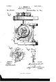
- FIG. 1 and 2 are respectively side elevation and top plan View of myimproved invention.
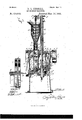
- Fig. 3 is a longitudinal vertical sectional view taken on line Fig. 2.
- Fig. 4t is a top plan View of the detached revoluble support which contains the chambers for forming the mince-meat into blocks.
- Fig. 7 is a transverse horizontal sectional view on line y y, Fig. 3.
- Fig. 8 is a top plan view of the plate beneath which the forming-chambers revolve;
- Figs. 9 and 10 are respectively side elevation and top plan View of the cam for reciprocating the plungers, and
- Fig. l1 is ⁇ a detail perspective View.
- My invention is designed to form the previously-prepared mince-meat into blocks of a uniform size and weight without the necessity of hand-labor, except the mere wrapping of the blocks, which, owing to their consistency after passage through the machine, are readily and quickly handled, thus reducing the cost of manufacture very materially and enhancing the uniformity, appearance, and value of the article produced.
- A represents the frame of the machine, which is of desirable form,size, and construction, being here Villustrated as composed of the top plate a, standards a', and bottom plate a2, supported at the central part of said standards by brackets a3,
- B represents the motor-shaft, having one extremity journaled in the bracket B and the other in a bearing B2, formed on the frameof the machine.
- a pulley b which is driven by any suitable power-transmitting mechanism, as a belt b', and at the opposite extremity of the shaft B is suitable gearing c, which transmits motion to a vertiroo cal shaft C, journaled in the frame A and adapted to transmit motion tothe conveyer for feeding the mince-meat to the formingchambers and designed to revolve the support for said conveyers, as presently described.
- the mince-meat when prepared for the operation of mymachine is filled'into a suitable chamber D, whence it is continually fed to the forming-chambers, it being evident that as the supply is exhausted in the chamber D 1t is constantly replenished.
- Beneath the chamber D is a plate E, secured to the frame A at E', and beneath the plate E is the revoluble support F, which contains the formingchambers F3 and is rigidly secured to the shaft C.
- the chamber D is enlarged in area at its upper extremity to permitl ready inlet of the material and is supported upon a sleeve D encircling the upper extremity of the shaft C and mounted upon the plate E.
- an arm d Extending laterally from the sleeve D is an arm d, and journaled therein is a vertical shaft d', the lower end of which revolves within the chamber D and is provided with a spiral conveyer d2 of a shape similar to that of the interior of the chamber D for continually forcing the mincemeat into the chambers F2 through the exitopening cl2 of the chamber D and the openings e through the plate E.
- the opening c (best seen at Fig.
- Motion is transmitted to the con veyer-shaft d by means of sprocket-wheels d4 and d, mounted upon the respective shafts d and O and connected by a sprocket chain or belt d6.
- the support F consists of an upper plate F', having a series of guideways or chambers F2, in which the mince-meat is compressed by the plungers H, movable in said guideways or chambers.
- the outer wall F3 (best seen at Fig. 1l) of the guideways or chambers F2 is removably secured at F4 to the remainder of the support F, and at Figs. 5 and G the detached support F is shown with all of said outer walls F3 removed for the purpose of further illustrating the construction of said support.
- the G represents vertical arms depending from the inner and outer walls F6 and F3 of the chambers F2, the lower extremity of the inner arms G being secured to a plate G carried by the vertical shaft C.
- the upper extremities of the adjacent faces of the arms G are disposed in the same plane as the corresponding faces of the inner and outer walls FG and F3 of the chambers F2, and the lower ends of said faces of the arms G are provided with ribs g, which project toward each other from said arms and form guides g for the plungerl-L
- the plunger H is designed to compress' the mince-meat within the chambers F2 into blocks of the required size and to discharge said blocks from said chambers.
- plunger The upper extremity of this plunger closely its the guideways or chambers F2 and is lnovably mounted ltherein, and the other extremity extends downwardly between the outer and inner arms G, is formed with ribs 7L, movable in the guideways g of said arms G, and is cut away at h for the purpose of lightening the plunger.
- plunger is formed, as described, by ribs g, projecting beyond the plane of the superimposed wall of the chamber F2, and said chamber is formed with a removable wall having vlike projecting ribs at its lower extremity in order that the frame composing said chamber and its removable wall may be cast to the desired form and the guides g then formed by an ordinary planer, thus reducing the cost 0f these parts to a minimum.
- an anti-friction roller h2 At the lower extremity of the plunger is an anti-friction roller h2, which bears upon the top edge of a cam I, mounted upon the table a2 and adapted to reciprocate the plunge
- the depression 0l of the cam l is directly beneath the exit d3 of the chamber D and the opening e of the plate E, so that when the chamber F2 is in alignment with said exit d2 the material is free to feed into the chamber until by the revolution of the supportF the table E forms a cut-off for the chamber F2.
- formed in the plate E is of considerable less area than the inlet e to the chamber F2 and is in advance of said inlet, so that as soon as the plunger His raised by the portion i2 of the cam-tooth i the chamber is aligned with the exit e and the excess of material immediately escapes to the top of the plate E, being prevented from spreading by an upright flange E2 upon said plate.
- the plunger still has a slight movement, in order to further compress and shape the block after the excess of material hasbeen expelled, and after such operation the chamber F2 passes from beneath the plate E, and the portion i3 of the cam elevates the plunger l-l a sufficient distance to expel the block 0f mince-meat from the chamber F2, whereupon it is readily engaged by the attendant, after which the lower vend of the plunger registers with a cut-out t2 in the cam and assumes its lower position to permit inlet of the mince-meat upon registration of the chamber F2 with the exit d3.
- the i'lowof the Water is so regulated as to afford ⁇ the desired amount of moisture and entirely obviates the difficulty referred to.
- a carrier K which may be of any desirable form, size, and construction, preferably consisting of a beit 7a, passed over a pulley 7a', which is mounted on the shaft 7a2, driven from the shaft B by a belt 7c3.
- he top face of the belt 7c is slightly elevated above the table a, and is arranged in close proximity to the erator may readily remove the blocks to the belt, whence they will be fed onward to any suitable table, and may then be quickly wrapped in the usual wrapping-paper or packed in any other desirable manner.
- a mince-meat machine the combination of a movable chamber for receiving the mince-meat, a plate above the chamber for forming the top wall thereof, and a plunger mounted in said chamber and movable toward said Vplate for compressing the mince-meat between the plate and plunger, substantially as and for the purpose set forth.
- a mince-meat machine the combination of a movable frame having the chamber for receiving the mince-meat, a plate above the chamber forforming the top wall thereof, a plunger having one extremity mounted in support Fiu order that the op- ⁇ said chamber and movable toward the plate for compressing the mince-meat between the plate and plunger, projecting ribs on the plunger, and guides on said frame for Athe plunger-ribs,snbstantiallyas and for thepurpose described.
- a mince-meat machine the combination of a chamber for receiving the mincemeat, a second chamber movable beneath the former chamber for receiving the mince-meat from the former chamber, a plate above the latter chamber for forming the top wall thereof, and a plunger mounted in said chamber and movable toward said plate for compressing the mince-meat between the plate and plunger, substantially as and for the purpose set forth.
- a mince-meat machine the combination of a movable frame having aseries of chambers for receiving the mince-meat, a plate above said chambers adapted to form the top wall thereof. and arranged with one edge above the frame, whereby the chambers pass from beneath said plate, and a plunger movable toward said frame forcompressing the mince-meat between the plate and frame, said plunger being further movable after the chamber has passed said edge of the plate for discharging the mince-meat from the chamber, substantially as set fort-h. 5.
- a mince-meat machine In a mince-meat machine, the combination of a movable frame having a series of chambers for ,receiving the mince-meat, a plate mounted above the chambers for forming the top wall thereof and formed with an opening of greater length in one plane than the corresponding cross-sectional length of the chambers, whereby when one chamber is passing beneath the plate from one extremity of said opening the succeeding chamber is registering with the opposite extremity of said opening, and plungers movably mounted in said chambers for compressing the mincemeat between the plate and plungers, substantially as and for the purpose described.
- a mince-meat machine the combination of a chamber adapted to receive the mince-meat and provided with a .dischargeopening, a movableframe provided with a se- IOO ries of chambers movable beneath the discharge-opening of the former chamber, a conveyer within the former chamber for forcing the material through said discharge-opening into the latter chambers, a plate mounted above the latter chambers for forming the top wall thereof, and plungers movably mounted in said latter chambers for compressing the mince-meat between the plate and plungers, substantially as and for the purpose specified.
- a mince-meat machine the combina- ⁇ tion of a movable chamber for receiving an excess of the mince-meat, a plate mounted above the chamber for forming the top wall thereof and provided with an exit-opening for the excess of material, and a plunger movably mounted in said chamber for forcing the material against said plate and discharging the excess through said exit-opening, substantially as and for the purpose set forth.
- a mince-meat machine the combination of a chamber for receiving the mincemeat, a second chamber of sufficient area when open to receive an excess of the mincemeat and provided With an outlet for discharging said excess, and a plunger rnovably mounted-in the latter chamber for compressing the mince-meat and discharging the excess through said outlet-opening, substantially as specified.
- a movable frame having a chamber for receiving the mince-meat, a plate above Ihechamber for forming the top Wall thereof, a pipe for supplying Water to said chamber, and a plunger mounted in said chamber and movable toward said plate for compressing the mince-meat between the plate and plunger, substantially as set forth.
- a mince-meat machine the combination of a plate, a frame movable beneath the plate, provided with chambers for receiving the meat and forming the same into blocks, an exit-opening in the plate for permitting outlet of the excess of material, a plunger movable in the chamber toward the plate for compressing the blocks and discharging them from the chamber, and a cam for raising said plunger, said cam having an incline for slightly raising the plunger after it is aligned with the said exit-opening, substantially as described.
- a mince-meat machine the combination of a plate having a pair of openings, one vof less area than the other, a chamber above said plate for receiving the mince-meat and discharging the same through the opening of greater area, a frame Vbeneath the plate, having a chamber for receiving an excess of material from the former chamber, and a plunger for forcing the excess of material through the opening of less area and discharging the compressed mince-meat from the chamber in said plate, substantially as specified.
- a4 mince-meat machine the combination of a plate having a pair of openings, one of less area than the other, a frame movable beneath the plate and provided with chambers forl receiving the meat and forming it into blocks, a conveycr for feeding the meat through the larger opening in said plate into the movable chambers, a plunger for-forcing the excess of material through said opening of less area, and a cam for reciprocating said plunger, substantially as set forth.
- a mince-meat machine the combination of a stationary table, a carrier in proximity to the table, a revolving frame arranged in proximity to the stationary table and formed With a series of chambers for receiving and compressing the mince-meat, a plate above the revolving frame, adapted to become the top Wall of said chambers, and plungers mounted in said chambers and movable toward said plate for compressing the mincemeat between the plate and plungers, substantially as described.
- a mince-meat machine the combination of a stationary table, a carrier in proximity to the table, a revolving frame arranged in proximity to the stationary table and formed with a series of chambers for receiving an excess of the mince-meat and compressing the same into blocks of the required size.
- a plate above the revolving frame adapted to become the top Wall of said chambers and formed with an outlet-opening for the excess of material, plungers mounted in said chambers and movable toward said plate for compressing the mincemeat between the plate and plungers, and a guard on said plate for preventing the escape of the mince-meat therefrom, substantially as and for the purpose set forth.
Landscapes
- Engineering & Computer Science (AREA)
- Manufacturing & Machinery (AREA)
- Mechanical Engineering (AREA)
- Meat, Egg Or Seafood Products (AREA)
Description
4 Sheets-Sheet 1.
GQL. MERRELL. MINE MBATMACHINE.
Patented Mar. 15, 1892.
(No Model.) r 4 sheets-sheet 2:.
G. L. MERRELL.' MINCE MEAT MACHINE.
No. 470,692. Patented Mar. 15, 18927.
4 YSheets-Sheet 3.
' (No Model.)
G. LQ MERRELL. MINCB MEAT MACHINE.
WITNESSES:
me Ncmms Pneus co., mmoumo., wAsmNacN. n. c,
(No Model.) 4 sheets-sheet 4.
G. L. MERRELL.
MINGB MEAT MAGHINE.
No. 470,692. Patented Mar. 15, 1892.
i l r 6 are respectively top plan and side elevation of said revoluble support, illustrating the same as with the outer walls of the blockforming chambers removed therefrom. Fig.
vention furthermore consists in a carrier or yUNITED STATES PATENT Grrrcn.
GAIUS LEWIS MERRELL, OF SYRACUSE, NEW YORK.
IVIINCE-IVIEAT MACHINE.
SPECIFICATION forming part of Letters Patent No. 470,692, dated March 15, 1892.
Application inea May 1s, 1891.
To all whom it may concern:
Be it known that I, GAIUs LEWIS MERRELL,. of Syracuse, in the county of Onondaga, in the State of New York, have invented new and useful Improvements in Mince-Meat Machines, of which the following, taken in connection with the accompanying drawings, is a full, clear, and exact description.
My invention relates to improvements in mince-meat machines, and has for its object the production of a simple and effective device vwhereby the mince-meat previously prepared is formed into blocks of equal size and weight, thus obviating the necessity of hand-Weighing, and bringing the blocks to a uniform size and of sufficient firmness to be readily handled, as required by the consequent wrapping in paper to which said blocks are subjected in packing; and to this end the invention consists, essentially, in a chamber for containing the prepared mincemeat, a revoluble support. having a series of chambers movable beneath the former chamber for receiving the meat, plungers movably mounted in said chambers for pressing and discharging the blocks of meat, and an exitopen-ing from the latter chambers for permitting outlet of the excess of material. The inendless belt lmovable in proximity y to the point Where the blocks are discharged for permitting their ready removal from the machine; and it furthermore consists in the detail construction and arrangement of the parts, all as hereinafter more particularly described, and pointed out in the claims.
In describing this invention reference is had to the accompanying drawings, forming a part of this specification, in which like lettersindicate corresponding parts in allthe views. u Figures 1 and 2 are respectively side elevation and top plan View of myimproved invention. Fig. 3 is a longitudinal vertical sectional view taken on line Fig. 2. Fig. 4t is a top plan View of the detached revoluble support which contains the chambers for forming the mince-meat into blocks. Figs. 5 and Serial No. 393,068. (No model.)
7 is a transverse horizontal sectional view on line y y, Fig. 3. Fig. 8 is a top plan view of the plate beneath which the forming-chambers revolve; Figs. 9 and 10 are respectively side elevation and top plan View of the cam for reciprocating the plungers, and Fig. l1 is `a detail perspective View.
It is well known that at present acommercial mince-meat is placed upon themarket in a substantially dry condition, being packed in small boxes containinga uniform amount, usually one pound. I-Ieretofore the mincerneat after being brought to the desired condition for packing and when quite moist has been weighed by hand to insure uniformity and protect both the manufacturer and buyer and has afterward been formed by hand into a block and wrapped in paper before being placed in an incasing box, in which the mincemeat remains until used. This handling of each separate package consumes a great amount of time, and even when the operator is extremely careful such is the speed at which -he must work that the blocks vary considerably in size and greatly in form.
My invention is designed to form the previously-prepared mince-meat into blocks of a uniform size and weight without the necessity of hand-labor, except the mere wrapping of the blocks, which, owing to their consistency after passage through the machine, are readily and quickly handled, thus reducing the cost of manufacture very materially and enhancing the uniformity, appearance, and value of the article produced.
A represents the frame of the machine, which is of desirable form,size, and construction, being here Villustrated as composed of the top plate a, standards a', and bottom plate a2, supported at the central part of said standards by brackets a3,
B represents the motor-shaft, having one extremity journaled in the bracket B and the other in a bearing B2, formed on the frameof the machine. Upon the shaft Bis a pulley b, which is driven by any suitable power-transmitting mechanism, as a belt b', and at the opposite extremity of the shaft B is suitable gearing c, which transmits motion to a vertiroo cal shaft C, journaled in the frame A and adapted to transmit motion tothe conveyer for feeding the mince-meat to the formingchambers and designed to revolve the support for said conveyers, as presently described.
The mince-meat when prepared for the operation of mymachine is filled'into a suitable chamber D, whence it is continually fed to the forming-chambers, it being evident that as the supply is exhausted in the chamber D 1t is constantly replenished. Beneath the chamber D is a plate E, secured to the frame A at E', and beneath the plate E is the revoluble support F, which contains the formingchambers F3 and is rigidly secured to the shaft C. As best illustrated in Figs. l and 3, the chamber D is enlarged in area at its upper extremity to permitl ready inlet of the material and is supported upon a sleeve D encircling the upper extremity of the shaft C and mounted upon the plate E. Extending laterally from the sleeve D is an arm d, and journaled therein is a vertical shaft d', the lower end of which revolves within the chamber D and is provided with a spiral conveyer d2 of a shape similar to that of the interior of the chamber D for continually forcing the mincemeat into the chambers F2 through the exitopening cl2 of the chamber D and the openings e through the plate E. It will be noted that the opening c (best seen at Fig. S) in the plate E is of greater length than the corresponding cross-sectional length of the chambers F2, whereby when the chamber which has just been filled is being moved beneath said plate out of registration with the open ing the succeeding chamber F2 is in registration with the opposite end of said opening for rendering the passage of the mince-meat to said chambers continuous.
Motion is transmitted to the con veyer-shaft d by means of sprocket-wheels d4 and d, mounted upon the respective shafts d and O and connected by a sprocket chain or belt d6.
As illustrated, the support F consists of an upper plate F', having a series of guideways or chambers F2, in which the mince-meat is compressed by the plungers H, movable in said guideways or chambers. As shown at Figs. 1 and 4, the outer wall F3 (best seen at Fig. 1l) of the guideways or chambers F2 is removably secured at F4 to the remainder of the support F, and at Figs. 5 and G the detached support F is shown with all of said outer walls F3 removed for the purpose of further illustrating the construction of said support.
G represents vertical arms depending from the inner and outer walls F6 and F3 of the chambers F2, the lower extremity of the inner arms G being secured to a plate G carried by the vertical shaft C. The upper extremities of the adjacent faces of the arms G are disposed in the same plane as the corresponding faces of the inner and outer walls FG and F3 of the chambers F2, and the lower ends of said faces of the arms G are provided with ribs g, which project toward each other from said arms and form guides g for the plungerl-L The plunger H is designed to compress' the mince-meat within the chambers F2 into blocks of the required size and to discharge said blocks from said chambers. The upper extremity of this plunger closely its the guideways or chambers F2 and is lnovably mounted ltherein, and the other extremity extends downwardly between the outer and inner arms G, is formed with ribs 7L, movable in the guideways g of said arms G, and is cut away at h for the purpose of lightening the plunger. plunger is formed, as described, by ribs g, projecting beyond the plane of the superimposed wall of the chamber F2, and said chamber is formed with a removable wall having vlike projecting ribs at its lower extremity in order that the frame composing said chamber and its removable wall may be cast to the desired form and the guides g then formed by an ordinary planer, thus reducing the cost 0f these parts to a minimum. At the lower extremity of the plunger is an anti-friction roller h2, which bears upon the top edge of a cam I, mounted upon the table a2 and adapted to reciprocate the plunger.
As best seen at Figs. l and 3, the depression 0l of the cam l is directly beneath the exit d3 of the chamber D and the opening e of the plate E, so that when the chamber F2 is in alignment with said exit d2 the material is free to feed into the chamber until by the revolution of the supportF the table E forms a cut-off for the chamber F2.
In order to produce a well-formed block of the mince meat and bring the successive blocks to the same weight, l have discovered that it is absolutely necessary to open the chamber a sufficient amount to receive such a quantity of the material which, if solid or firm, is in excess of that required and to provide an exit-opening from said chamber for permitting the outlet of the excess of material. As preferably constructed, formed in the plate E is of considerable less area than the inlet e to the chamber F2 and is in advance of said inlet, so that as soon as the plunger His raised by the portion i2 of the cam-tooth i the chamber is aligned with the exit e and the excess of material immediately escapes to the top of the plate E, being prevented from spreading by an upright flange E2 upon said plate. After the chamber has passed this exit the plunger still has a slight movement, in order to further compress and shape the block after the excess of material hasbeen expelled, and after such operation the chamber F2 passes from beneath the plate E, and the portion i3 of the cam elevates the plunger l-l a sufficient distance to expel the block 0f mince-meat from the chamber F2, whereupon it is readily engaged by the attendant, after which the lower vend of the plunger registers with a cut-out t2 in the cam and assumes its lower position to permit inlet of the mince-meat upon registration of the chamber F2 with the exit d3. The
this exit e.
The guide for the IOO IIO
`and upon fing thereby carried within the chambers F2.
ily perceived from the foregoing ment after the block is formed to the desired' size. Consequently I provide the pipe J, having one extremity connected to any suitable water source and the other discharging slowly upon the top face of the revolnble support F the top face of the plungers H, be-
The i'lowof the Water is so regulated as to afford` the desired amount of moisture and entirely obviates the difficulty referred to.
In order to withdraw the blocks from the machine, I provide a carrier K, which may be of any desirable form, size, and construction, preferably consisting of a beit 7a, passed over a pulley 7a', which is mounted on the shaft 7a2, driven from the shaft B by a belt 7c3. he top face of the belt 7c is slightly elevated above the table a, and is arranged in close proximity to the erator may readily remove the blocks to the belt, whence they will be fed onward to any suitable table, and may then be quickly wrapped in the usual wrapping-paper or packed in any other desirable manner.
The operation of my invention willbe readdescription and upon reference to the drawings, and itis evident that the blocks of mince-meat are all brought to a uniform size and weight, that they are rendered extremely firm, are readily wrapped and packed away, and handled with great ease and convenience, thus reducing'the cost of manufacture, simplifying the production of commercial mince-meat, and adding to the appearance of the blocks. It is evident, however` that considerable change may be made in the detail construction and arrangment of the parts of my invention without departing from the spirit thereof.
IIaving thusfully described my invention, what I claim as new, and desire to secure by Letters Paten t, is-
1. In a mince-meat machine, the combination of a movable chamber for receiving the mince-meat, a plate above the chamber for forming the top wall thereof, and a plunger mounted in said chamber and movable toward said Vplate for compressing the mince-meat between the plate and plunger, substantially as and for the purpose set forth.
2. In a mince-meat machine, the combination of a movable frame having the chamber for receiving the mince-meat, a plate above the chamber forforming the top wall thereof, a plunger having one extremity mounted in support Fiu order that the op-` said chamber and movable toward the plate for compressing the mince-meat between the plate and plunger, projecting ribs on the plunger, and guides on said frame for Athe plunger-ribs,snbstantiallyas and for thepurpose described.
3. In a mince-meat machine, the combination of a chamber for receiving the mincemeat, a second chamber movable beneath the former chamber for receiving the mince-meat from the former chamber, a plate above the latter chamber for forming the top wall thereof, and a plunger mounted in said chamber and movable toward said plate for compressing the mince-meat between the plate and plunger, substantially as and for the purpose set forth. p
4t. In a mince-meat machine, the combination of a movable frame having aseries of chambers for receiving the mince-meat, a plate above said chambers adapted to form the top wall thereof. and arranged with one edge above the frame, whereby the chambers pass from beneath said plate, and a plunger movable toward said frame forcompressing the mince-meat between the plate and frame, said plunger being further movable after the chamber has passed said edge of the plate for discharging the mince-meat from the chamber, substantially as set fort-h. 5. In a mince-meat machine, the combination of a movable frame having a series of chambers for ,receiving the mince-meat, a plate mounted above the chambers for forming the top wall thereof and formed with an opening of greater length in one plane than the corresponding cross-sectional length of the chambers, whereby when one chamber is passing beneath the plate from one extremity of said opening the succeeding chamber is registering with the opposite extremity of said opening, and plungers movably mounted in said chambers for compressing the mincemeat between the plate and plungers, substantially as and for the purpose described.
6. In a mince-meat machine, the combination of a chamber adapted to receive the mince-meat and provided with a .dischargeopening, a movableframe provided with a se- IOO ries of chambers movable beneath the discharge-opening of the former chamber, a conveyer within the former chamber for forcing the material through said discharge-opening into the latter chambers, a plate mounted above the latter chambers for forming the top wall thereof, and plungers movably mounted in said latter chambers for compressing the mince-meat between the plate and plungers, substantially as and for the purpose specified.
7. In a mince-meat machine, the combina-` tion of a movable chamber for receiving an excess of the mince-meat, a plate mounted above the chamber for forming the top wall thereof and provided with an exit-opening for the excess of material, and a plunger movably mounted in said chamber for forcing the material against said plate and discharging the excess through said exit-opening, substantially as and for the purpose set forth.
8. In a mince-meat machine, the combination of a chamber for receiving the mincemeat, a second chamber of sufficient area when open to receive an excess of the mincemeat and provided With an outlet for discharging said excess, and a plunger rnovably mounted-in the latter chamber for compressing the mince-meat and discharging the excess through said outlet-opening, substantially as specified.
9. In a mince-meat machine, the combination of a movable frame having a chamber for receiving the mince-meat, a plate above Ihechamber for forming the top Wall thereof, a pipe for supplying Water to said chamber, and a plunger mounted in said chamber and movable toward said plate for compressing the mince-meat between the plate and plunger, substantially as set forth.
10. In a mince-meat machine` the combination of a plate, a frame movable beneath the plate, provided with chambers for receiving the meat and forming the same into blocks, an exit-opening in the plate for permitting outlet of the excess of material, a plunger movable in the chamber toward the plate for compressing the blocks and discharging them from the chamber, and a cam for raising said plunger, said cam having an incline for slightly raising the plunger after it is aligned with the said exit-opening, substantially as described.
11. In a mince-meat machine, the combination of a plate having a pair of openings, one vof less area than the other, a chamber above said plate for receiving the mince-meat and discharging the same through the opening of greater area, a frame Vbeneath the plate, having a chamber for receiving an excess of material from the former chamber, and a plunger for forcing the excess of material through the opening of less area and discharging the compressed mince-meat from the chamber in said plate, substantially as specified.
12. In a4 mince-meat machine, the combination of a plate having a pair of openings, one of less area than the other, a frame movable beneath the plate and provided with chambers forl receiving the meat and forming it into blocks, a conveycr for feeding the meat through the larger opening in said plate into the movable chambers, a plunger for-forcing the excess of material through said opening of less area, and a cam for reciprocating said plunger, substantially as set forth.
13. In a mince-meat machine, the combination of a stationary table, a carrier in proximity to the table, a revolving frame arranged in proximity to the stationary table and formed With a series of chambers for receiving and compressing the mince-meat, a plate above the revolving frame, adapted to become the top Wall of said chambers, and plungers mounted in said chambers and movable toward said plate for compressing the mincemeat between the plate and plungers, substantially as described.
14C. In a mince-meat machine, the combination of a stationary table, a carrier in proximity to the table, a revolving frame arranged in proximity to the stationary table and formed with a series of chambers for receiving an excess of the mince-meat and compressing the same into blocks of the required size. a plate above the revolving frame, adapted to become the top Wall of said chambers and formed with an outlet-opening for the excess of material, plungers mounted in said chambers and movable toward said plate for compressing the mincemeat between the plate and plungers, and a guard on said plate for preventing the escape of the mince-meat therefrom, substantially as and for the purpose set forth.
l5. In a mince-meat machine, the combination of a block having a series of guideways, guide-ribs beneath the guideways and proj ect-ing beyond and perpendicular to the Wall of the guideway above the same,a removable wall adapted to be secured to said guideway, guide-ribs provided in said Wall, and plungers movable in said guideways With one extremity guided by said guide-ribs, substantially as andfor the purpose specified.
In testimony whereof I have hereunto signed my name, in the presence of two attesting Witnesses, at Syracuse, in the county of Onondaga, in the State of New York, this 14th day of May, 1891.
` GAIUS LEWIS MERRELL. Nitnessess CLARK H. NORTON,
E. A. WEISBURG.
Publications (1)
| Publication Number | Publication Date |
|---|---|
| US470692A true US470692A (en) | 1892-03-15 |
Family
ID=2539552
Family Applications (1)
| Application Number | Title | Priority Date | Filing Date |
|---|---|---|---|
| US470692D Expired - Lifetime US470692A (en) | Mince-meat machine |
Country Status (1)
| Country | Link |
|---|---|
| US (1) | US470692A (en) |
Cited By (5)
| Publication number | Priority date | Publication date | Assignee | Title |
|---|---|---|---|---|
| US2641797A (en) * | 1949-03-22 | 1953-06-16 | Edgar P Guice | Shrimp assimilating machine |
| US2757411A (en) * | 1952-12-01 | 1956-08-07 | Grand Duchess Steaks Inc | Apparatus for forming and sorting meat patties |
| US3304855A (en) * | 1963-05-15 | 1967-02-21 | H G Molenaar & Company Proprie | Extractor means for extracting liquid from a liquids containing mass |
| US4987643A (en) * | 1989-08-10 | 1991-01-29 | Marlen Research Corporation | Slide plate patty forming apparatus |
| WO1992001451A1 (en) * | 1990-06-12 | 1992-02-06 | Board Of Regents, The University Of Texas System | Method for killing hiv-infected cells |
-
0
- US US470692D patent/US470692A/en not_active Expired - Lifetime
Cited By (5)
| Publication number | Priority date | Publication date | Assignee | Title |
|---|---|---|---|---|
| US2641797A (en) * | 1949-03-22 | 1953-06-16 | Edgar P Guice | Shrimp assimilating machine |
| US2757411A (en) * | 1952-12-01 | 1956-08-07 | Grand Duchess Steaks Inc | Apparatus for forming and sorting meat patties |
| US3304855A (en) * | 1963-05-15 | 1967-02-21 | H G Molenaar & Company Proprie | Extractor means for extracting liquid from a liquids containing mass |
| US4987643A (en) * | 1989-08-10 | 1991-01-29 | Marlen Research Corporation | Slide plate patty forming apparatus |
| WO1992001451A1 (en) * | 1990-06-12 | 1992-02-06 | Board Of Regents, The University Of Texas System | Method for killing hiv-infected cells |
Similar Documents
| Publication | Publication Date | Title |
|---|---|---|
| US470692A (en) | Mince-meat machine | |
| US692903A (en) | Measuring-machine for plastic material. | |
| US1425374A (en) | Apparatus for sorting out and delivering bodies or lids of tins or the like | |
| US794130A (en) | Pie-machine. | |
| US843565A (en) | Briquet-making machine. | |
| US1233261A (en) | Filling-machine. | |
| US741466A (en) | Apparatus for boxing matches. | |
| US805324A (en) | Molding apparatus. | |
| US1257523A (en) | Machine for subdividing plastic substances. | |
| US1752890A (en) | Plastic material measuring and filling machine | |
| US846658A (en) | Cigarette-box making and packing machine. | |
| US584401A (en) | Oil cake teimmee | |
| US54476A (en) | Improvement in machines for making fillers for cigars | |
| US715336A (en) | Machine for packing pulverulent and mastic substances. | |
| US713491A (en) | Machine for filling and closing paper boxes. | |
| US391795A (en) | Can-filling machine | |
| US418887A (en) | Ttxitti | |
| US1331693A (en) | Candy-molding machine | |
| US1257012A (en) | Filling-machine. | |
| US3913791A (en) | Conveying apparatus, especially for granular and lump form material | |
| US836787A (en) | Machine for dividing measured charges from a mass of material. | |
| US845299A (en) | Feeder for briquet-machines. | |
| US747328A (en) | Machine for shaping and pressing plastic material. | |
| US1360438A (en) | pa-ridon | |
| US594968A (en) | Machine for wrapping and securing tobacco in packets |