US4706561A - Printing activator test circuit generating back EMF - Google Patents
Printing activator test circuit generating back EMF Download PDFInfo
- Publication number
- US4706561A US4706561A US06/850,436 US85043686A US4706561A US 4706561 A US4706561 A US 4706561A US 85043686 A US85043686 A US 85043686A US 4706561 A US4706561 A US 4706561A
- Authority
- US
- United States
- Prior art keywords
- printing
- signal
- detecting
- electromotive force
- circuit
- Prior art date
- Legal status (The legal status is an assumption and is not a legal conclusion. Google has not performed a legal analysis and makes no representation as to the accuracy of the status listed.)
- Expired - Lifetime
Links
Images


Classifications
-
- B—PERFORMING OPERATIONS; TRANSPORTING
- B41—PRINTING; LINING MACHINES; TYPEWRITERS; STAMPS
- B41J—TYPEWRITERS; SELECTIVE PRINTING MECHANISMS, i.e. MECHANISMS PRINTING OTHERWISE THAN FROM A FORME; CORRECTION OF TYPOGRAPHICAL ERRORS
- B41J9/00—Hammer-impression mechanisms
- B41J9/16—Means for cocking or resetting hammers
-
- B—PERFORMING OPERATIONS; TRANSPORTING
- B41—PRINTING; LINING MACHINES; TYPEWRITERS; STAMPS
- B41J—TYPEWRITERS; SELECTIVE PRINTING MECHANISMS, i.e. MECHANISMS PRINTING OTHERWISE THAN FROM A FORME; CORRECTION OF TYPOGRAPHICAL ERRORS
- B41J29/00—Details of, or accessories for, typewriters or selective printing mechanisms not otherwise provided for
- B41J29/38—Drives, motors, controls or automatic cut-off devices for the entire printing mechanism
- B41J29/393—Devices for controlling or analysing the entire machine ; Controlling or analysing mechanical parameters involving printing of test patterns
Definitions
- the present invention relates to a print activator test circuit and particularly to testing the operativeness or inoperativeness of electrical circuits involved in a printing operation without actually effecting printing during the test process.
- the object of the invention is to obviate such problems by providing a control arrangement for detecting the operativeness of an electrical circuit by employing a driving signal of shortened duration sufficient to produce a driver signal output to indicate operativeness or inoperativeness but not sufficient to cause printing by an associated printing element and a common detection means.
- the above object is attained, according to the invention, in one embodiment involving the detection of the operability of a plurality of printing element drivers employed for activating respective printing elements for printing along a print line on a record medium without causing printing.
- This arrangement comprises means for sequentially energizing each of said drivers with a shortened duration drive pulse sufficient to produce a reverse electromotive force signal in an associated coil but not sufficient to cause printing by an associated printing element. Means are then provided for detecting the effective absence of said reverse electromotive force signal indicating an inoperative coil driver or an open or shorted coil during determination of each such sequential energizing. This detection results in an error signal which is then used to produce an information signal indicative of coil and/or coil driver inoperativeness.
- FIG. 1 illustrates in block diagram form the overall invention for detecting the operativeness or inoperativeness of coil driver circuits used in a printer
- FIG. 2 illustrates in circuit diagram form the details of the driver elements used to activate the printing elements. The number of such driver circuits would correspond to the number of printing elements.
- FIG. 3 illustrates in block diagram and schematic form the details of the detector mentioned in FIG. 1;
- FIG. 4 illustrates graphically certain waveforms useful in explaining the operation of the invention.
- FIG. 1 there is shown in simplified block diagram form the details of the present invention.
- a printer involving printing elements such as dot matrix print styli
- FIG. 1 there is shown a plurality of printing elements 1 which in the case of styli would be driven towards a record medium as, for example, paper, and cause printing to take place via an inked ribbon which is not shown but is placed between the record medium and the printing element.
- the number of printing elements depends on the number of dots desired to be printed in a vertical line in the case of a serial printer and in a horizontal line in the case of a shuttle printer.
- Each of the printer elements is driven by a respective printing element driver which in one embodiment involves a solenoidal coil actuator. Signals applied to each of the coils of the drivers causes a magnetic field to drive the associated stylus into the record medium.
- a sequential driver energizer 3 which operates to sequentially apply signals over respective leads 4 to each of the printing element drivers 2. The use of the sequential driving signals for test purposes offers certain advantages.
- a sequential output signal can be obtained to indicate the state of operativeness of the individual energized drivers.
- These sequential output signals can be detected by a single detector circuit. Thus each individual driver does not require a separate detector.
- printing normally takes place under the control of signals supplied from an information source 5. The manner in which this is accomplished is well known in the art.
- a test initiate signal is generated under operator or remote control in block 6. This test initiate signal applied to the sequential driver energizer 3 causes test pulses to be sequentially applied over each of the leads 4 to the associated printing element drivers 2. These test pulses are of shorter duration than the normal print actuation pulses in order to obtain a signal of operativenss or inoperativeness of the drivers 2 without actually causing printing by the printing elements 1. This will be described in greater detail later.
- the printing element drivers 2 upon operating in response to the test initiate signals from 6, produce output signals V 1-N on lead 7 indicating the operativeness or inoperativeness of the respective driver elements in 2. These signals on 7 are detected by a detector 8 which then supplies an indication signal V p over lead 9 to the indicator 10 to indicate the operativeness and/or inoperativeness of the individual printing element drivers 2.
- the indicator 10 may be a numerical display which indicates, numerically, which ones of the driver elements 2 are operative or inoperative, or may simply produce a signal indicating there exists an inoperative driver. The details of how these indications can be obtained are well known in the art.
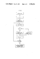
- FIG. 5 there is described a program in flow chart form for indicating which, if any, of the individual printing element drivers tested operative or inoperative. It is sufficient for purposes of this discussion to say that 10 produces an indication of the operativeness or inoperativeness of the individual element drivers 2.
- FIG. 2 there is shown in greater detail one embodiment of a driver circuit 2.
- the drive signals available from 3 are shown being applied to one particular driver circuit 2 shown in FIG. 2. This would be a pulse of 250 microseconds duration applied over lead 4 to the driver, through transistors Q1 and Q2 producing a current in coil L, to effect printing.
- L was a solenoidal actuator.
- Q1 and Q2 are turned on and off in response to a signal on lead 4.
- FIG. 2 operates as a current regulating driver and produces current I L in coil L.
- FIG. 4A illustrates such a current in the first waveform segment 11.
- This regulated current waveform 11 consists of a pulse with an average amplitude of, in one example, the order of 2.4 amperes and a pulse width of 250 microseconds. This duration of current pulse is sufficient to cause printing to take place but is shortened as will be described shortly when a test operation is desired.
- the diodes D1 and D2 clamp the reverse electromotive force produced by the coil L at the end of the drive pulse to the 40 volts and remove stored energy from the coil quickly.
- the output signal V 1-N produced at the output of the driver in FIG. 2 is shown in greater detail in FIG. 4B in waveform segment 12 for the normal printing operation. The polarity of the voltage is positive with respect to the other end of the coil.
- diodes D1 and D2 become forward biased and the coil discharges into the voltage supply.
- the resulting voltage,waveform V 1-N is shown in FIG. 4B as segment 12.
- a shorted or open coil would not allow V 1-N to connect to the plus 40 V supply through D2.
- FIG. 3 One embodiment of a detector 8 as shown in FIG. 3 consists of individual diodes coupling the V 1-N signals to a detector circuit.
- the V 1-N signals available from the output of the driver 2 and ORed by the input diodes 14 onto lead 15 before application to the detector circuit. It should be noted that only one detector circuit is required for 1 to N driver circuits.
- the voltage on 15 is normally at a given level, say of the order of 36 volts.
- Q3 conducts and approximately 4.5 volts are then present at V p .
- Q3 turns on and V p returns the 4.5 volts when the V 1-N voltage falls below 36 volts.
- the V p waveform is shown in FIG. 4 segment B.
- V 1-N and V p pulses are essentially unchanged from the normal printing case. However, the printing elements, if a styles or wire, is not displaced enough to strike the paper and effect printing. Under this circumstance this negative going pulse is identified in the indicator 10 as an operative coil.
- the coil driving signals are selected to be of 90 microseconds duration as shown in FIG. 4A as contrasted with he normal printing duration of 250 microseconds. During the 90 microsecond period there is an insufficient driving force developed to cause the printing elements to effect printing but there is sufficient signal information developed in the coil L to be detected to indicate an operative or an inoperative condition.
Landscapes
- Dot-Matrix Printers And Others (AREA)
Abstract
Description
Claims (5)
Priority Applications (1)
| Application Number | Priority Date | Filing Date | Title |
|---|---|---|---|
| US06/850,436 US4706561A (en) | 1984-10-25 | 1986-04-08 | Printing activator test circuit generating back EMF |
Applications Claiming Priority (2)
| Application Number | Priority Date | Filing Date | Title |
|---|---|---|---|
| US66487884A | 1984-10-25 | 1984-10-25 | |
| US06/850,436 US4706561A (en) | 1984-10-25 | 1986-04-08 | Printing activator test circuit generating back EMF |
Related Parent Applications (1)
| Application Number | Title | Priority Date | Filing Date |
|---|---|---|---|
| US66487884A Continuation | 1984-10-25 | 1984-10-25 |
Publications (1)
| Publication Number | Publication Date |
|---|---|
| US4706561A true US4706561A (en) | 1987-11-17 |
Family
ID=27099078
Family Applications (1)
| Application Number | Title | Priority Date | Filing Date |
|---|---|---|---|
| US06/850,436 Expired - Lifetime US4706561A (en) | 1984-10-25 | 1986-04-08 | Printing activator test circuit generating back EMF |
Country Status (1)
| Country | Link |
|---|---|
| US (1) | US4706561A (en) |
Cited By (11)
| Publication number | Priority date | Publication date | Assignee | Title |
|---|---|---|---|---|
| US4862078A (en) * | 1987-05-07 | 1989-08-29 | Yamaha Corporation | Circuit for detecting defects of a magnetic recording head |
| US4875409A (en) * | 1987-07-01 | 1989-10-24 | Printronix, Inc. | Magnetic print hammer actuator protection circuit |
| US4939928A (en) * | 1988-04-29 | 1990-07-10 | Chrysler Corporation | Method of determining the continuity of solenoids in an electronic automatic transmission system |
| US4990895A (en) * | 1988-07-21 | 1991-02-05 | Opcon, Inc. | Method and apparatus for testing photoelectric circuits |
| US5017027A (en) * | 1988-08-22 | 1991-05-21 | Seiko Epson Corporation | Impact printer |
| US5186550A (en) * | 1988-08-22 | 1993-02-16 | Seiko Epson Corporation | Impact printer |
| US5204633A (en) * | 1992-02-25 | 1993-04-20 | International Business Machines Corporation | Electromagnetic contactor with closure fault indicator |
| US5383399A (en) * | 1993-09-27 | 1995-01-24 | Ncr Corporation | Zero hammer adjustment drum printer control technique |
| US5518326A (en) * | 1992-07-31 | 1996-05-21 | Fujitsu Limited | Impact printer which can detect partial defects in coils |
| US6483226B1 (en) * | 1999-03-30 | 2002-11-19 | Minolta Co., Ltd. | Impact actuator and equipment using the impact actuator |
| US9519450B1 (en) * | 2006-06-23 | 2016-12-13 | Open Invention Network, Llc | System and method for printer driver management in an enterprise network |
Citations (17)
| Publication number | Priority date | Publication date | Assignee | Title |
|---|---|---|---|---|
| US3573562A (en) * | 1967-09-08 | 1971-04-06 | Ibm | Magnet driver circuit |
| GB1234564A (en) * | 1967-05-24 | 1971-06-03 | ||
| US3740615A (en) * | 1971-03-20 | 1973-06-19 | Honeywell Inf Systems | Actuating and confirming device for printing electromagnets |
| US3742310A (en) * | 1970-04-07 | 1973-06-26 | Ciba Geigy Ag | Apparatus for monitoring the action of electromagnetically operated printing hammers |
| US3909681A (en) * | 1973-11-28 | 1975-09-30 | Honeywell Inf Systems | Driving circuit for printing electromagnet |
| US4177731A (en) * | 1976-07-26 | 1979-12-11 | Printronix, Inc. | Printer system ribbon drive having constant ribbon speed and tension |
| US4293888A (en) * | 1979-06-25 | 1981-10-06 | International Business Machines Corporation | Print hammer drive circuit with compensation for voltage variation |
| US4317412A (en) * | 1980-06-25 | 1982-03-02 | International Business Machines Corporation | Control system and method for testing print hammers in a high speed printer |
| US4339208A (en) * | 1980-09-25 | 1982-07-13 | Ncr Corporation | Optical sensing of wire matrix printers |
| US4353656A (en) * | 1980-10-14 | 1982-10-12 | Xerox Corporation | Moving coil, multiple energy print hammer system including a closed loop servo |
| US4381532A (en) * | 1981-06-18 | 1983-04-26 | International Business Machines Corporation | Constant energy drive circuit for electromagnetic print hammers |
| US4411540A (en) * | 1980-08-27 | 1983-10-25 | Canon Kabushiki Kaisha | Printing apparatus |
| US4556926A (en) * | 1982-09-27 | 1985-12-03 | Ricoh Company, Ltd. | Electromagnet driving circuit |
| US4579467A (en) * | 1981-09-21 | 1986-04-01 | Omron Tateisi Electronics Co. | Dot printer with predriving force for removing particles from dot pins |
| US4595935A (en) * | 1984-08-14 | 1986-06-17 | Ncr Canada Ltd. | System for detecting defective thermal printhead elements |
| US4612638A (en) * | 1984-04-09 | 1986-09-16 | Chrysler Corporation | Diagnostic protection circuit and method using tri-state control and positive feedback |
| US4649341A (en) * | 1983-04-21 | 1987-03-10 | Wabco Westinghouse Fahrzeugbremsen Gmbh | Inductive measuring arrangement for determining the position of a movable core member |
-
1986
- 1986-04-08 US US06/850,436 patent/US4706561A/en not_active Expired - Lifetime
Patent Citations (17)
| Publication number | Priority date | Publication date | Assignee | Title |
|---|---|---|---|---|
| GB1234564A (en) * | 1967-05-24 | 1971-06-03 | ||
| US3573562A (en) * | 1967-09-08 | 1971-04-06 | Ibm | Magnet driver circuit |
| US3742310A (en) * | 1970-04-07 | 1973-06-26 | Ciba Geigy Ag | Apparatus for monitoring the action of electromagnetically operated printing hammers |
| US3740615A (en) * | 1971-03-20 | 1973-06-19 | Honeywell Inf Systems | Actuating and confirming device for printing electromagnets |
| US3909681A (en) * | 1973-11-28 | 1975-09-30 | Honeywell Inf Systems | Driving circuit for printing electromagnet |
| US4177731A (en) * | 1976-07-26 | 1979-12-11 | Printronix, Inc. | Printer system ribbon drive having constant ribbon speed and tension |
| US4293888A (en) * | 1979-06-25 | 1981-10-06 | International Business Machines Corporation | Print hammer drive circuit with compensation for voltage variation |
| US4317412A (en) * | 1980-06-25 | 1982-03-02 | International Business Machines Corporation | Control system and method for testing print hammers in a high speed printer |
| US4411540A (en) * | 1980-08-27 | 1983-10-25 | Canon Kabushiki Kaisha | Printing apparatus |
| US4339208A (en) * | 1980-09-25 | 1982-07-13 | Ncr Corporation | Optical sensing of wire matrix printers |
| US4353656A (en) * | 1980-10-14 | 1982-10-12 | Xerox Corporation | Moving coil, multiple energy print hammer system including a closed loop servo |
| US4381532A (en) * | 1981-06-18 | 1983-04-26 | International Business Machines Corporation | Constant energy drive circuit for electromagnetic print hammers |
| US4579467A (en) * | 1981-09-21 | 1986-04-01 | Omron Tateisi Electronics Co. | Dot printer with predriving force for removing particles from dot pins |
| US4556926A (en) * | 1982-09-27 | 1985-12-03 | Ricoh Company, Ltd. | Electromagnet driving circuit |
| US4649341A (en) * | 1983-04-21 | 1987-03-10 | Wabco Westinghouse Fahrzeugbremsen Gmbh | Inductive measuring arrangement for determining the position of a movable core member |
| US4612638A (en) * | 1984-04-09 | 1986-09-16 | Chrysler Corporation | Diagnostic protection circuit and method using tri-state control and positive feedback |
| US4595935A (en) * | 1984-08-14 | 1986-06-17 | Ncr Canada Ltd. | System for detecting defective thermal printhead elements |
Cited By (12)
| Publication number | Priority date | Publication date | Assignee | Title |
|---|---|---|---|---|
| US4862078A (en) * | 1987-05-07 | 1989-08-29 | Yamaha Corporation | Circuit for detecting defects of a magnetic recording head |
| US4875409A (en) * | 1987-07-01 | 1989-10-24 | Printronix, Inc. | Magnetic print hammer actuator protection circuit |
| US4939928A (en) * | 1988-04-29 | 1990-07-10 | Chrysler Corporation | Method of determining the continuity of solenoids in an electronic automatic transmission system |
| US4990895A (en) * | 1988-07-21 | 1991-02-05 | Opcon, Inc. | Method and apparatus for testing photoelectric circuits |
| US5017027A (en) * | 1988-08-22 | 1991-05-21 | Seiko Epson Corporation | Impact printer |
| US5186550A (en) * | 1988-08-22 | 1993-02-16 | Seiko Epson Corporation | Impact printer |
| US5204633A (en) * | 1992-02-25 | 1993-04-20 | International Business Machines Corporation | Electromagnetic contactor with closure fault indicator |
| US5518326A (en) * | 1992-07-31 | 1996-05-21 | Fujitsu Limited | Impact printer which can detect partial defects in coils |
| US5383399A (en) * | 1993-09-27 | 1995-01-24 | Ncr Corporation | Zero hammer adjustment drum printer control technique |
| US6483226B1 (en) * | 1999-03-30 | 2002-11-19 | Minolta Co., Ltd. | Impact actuator and equipment using the impact actuator |
| US9519450B1 (en) * | 2006-06-23 | 2016-12-13 | Open Invention Network, Llc | System and method for printer driver management in an enterprise network |
| US10365991B1 (en) * | 2006-06-23 | 2019-07-30 | Open Invention Network Llc | System and method for printer driver management in an enterprise network |
Similar Documents
| Publication | Publication Date | Title |
|---|---|---|
| US4706561A (en) | Printing activator test circuit generating back EMF | |
| US4774526A (en) | Fault detection circuit for a thermal print head | |
| US4769657A (en) | Fault detection device for thermal printing head heating circuits | |
| JPH06102379B2 (en) | Device for detecting failure of heated ink jet printer | |
| JPH04286657A (en) | Circuit for detecting abnormality of piezoelectric element | |
| EP0072224B1 (en) | A device for checking the printing circuit of a thermal printer | |
| US4875409A (en) | Magnetic print hammer actuator protection circuit | |
| US4317412A (en) | Control system and method for testing print hammers in a high speed printer | |
| JP2901032B2 (en) | LED print head | |
| EP0152732B1 (en) | A fault protection system for a line printer | |
| CA1301539C (en) | Control for enabling flight timing of hammers during printing | |
| EP0387641A1 (en) | Automatic gap adjustment apparatus for printing head | |
| KR880001443A (en) | Printing controller | |
| EP0552719B1 (en) | Thermal head driving circuit | |
| EP0272287B1 (en) | Printer energy control circuit | |
| JPS6330154B2 (en) | ||
| US3998152A (en) | Protection system for hammer drive circuits in impact printers | |
| US4812062A (en) | Print hammer with flux detection for print pressure control | |
| EP0774359B1 (en) | Printer coil temperature sensor and method | |
| JPS59109381A (en) | Detecting circuit of abnormalities of impact printer | |
| JP2586373B2 (en) | Thermal head drive control method | |
| JPS58166083A (en) | Hammer alarm detecting method | |
| JPS61123566A (en) | Thermal printer | |
| JPH0531956A (en) | Electrophotographic recording device and LED array failure detection device | |
| JP2701073B2 (en) | Method and circuit configuration for generating information about type of printer head and method for driving printer head |
Legal Events
| Date | Code | Title | Description |
|---|---|---|---|
| AS | Assignment |
Owner name: GENICOM CORPORATION 1 GENERAL ELECTRIC DRIVE, WAYN Free format text: ASSIGNMENT OF ASSIGNORS INTEREST.;ASSIGNOR:GREER, JERRY L.;REEL/FRAME:004543/0688 Effective date: 19841107 Owner name: GENICOM CORPORATION A CORP. OF DE.,VIRGINIA Free format text: ASSIGNMENT OF ASSIGNORS INTEREST;ASSIGNOR:GREER, JERRY L.;REEL/FRAME:004543/0688 Effective date: 19841107 |
|
| STCF | Information on status: patent grant |
Free format text: PATENTED CASE |
|
| AS | Assignment |
Owner name: CHEMICAL BANK, A NY BANKING CORP., NEW YORK Free format text: SECURITY INTEREST;ASSIGNOR:GENICOM CORPORATION, A CORP. OF DE.;REEL/FRAME:005370/0360 Effective date: 19900427 |
|
| AS | Assignment |
Owner name: FIDELCOR BUSINESS CREDIT CORPORATION, 810 SEVENTH Free format text: SECURITY INTEREST;ASSIGNOR:GENICOM CORPORATION;REEL/FRAME:005521/0609 Effective date: 19900925 Owner name: GENICOM CORPORATION, GENICOM DRIVE, WAYNESBORO, VA Free format text: RELEASED BY SECURED PARTY;ASSIGNOR:CHEMICAL BANK;REEL/FRAME:005521/0662 Effective date: 19900926 |
|
| FPAY | Fee payment |
Year of fee payment: 4 |
|
| FPAY | Fee payment |
Year of fee payment: 8 |
|
| AS | Assignment |
Owner name: NATIONSBANK OF TEXAS, N.A., AS AGENT, TEXAS Free format text: SECURITY AGREEMENT;ASSIGNORS:GENICOM CORPORATION;PRINTER SYSTEMS CORPORATION;REEL/FRAME:007690/0994 Effective date: 19960112 Owner name: CIT GROUP/CREDIT FINANCE, INC., THE, NEW YORK Free format text: ASSIGNMENT OF ASSIGNORS INTEREST;ASSIGNOR:FIDELCOR BUSINESS CREDIT CORPORATION;REEL/FRAME:007749/0742 Effective date: 19910131 Owner name: GENICOM CORPORATION, VIRGINIA Free format text: RELEASE;ASSIGNOR:CIT GROUP/CREDIT FINANCE, INC., THE;REEL/FRAME:007764/0063 Effective date: 19960116 |
|
| FPAY | Fee payment |
Year of fee payment: 12 |
|
| AS | Assignment |
Owner name: GENICOM, LLC, VIRGINIA Free format text: ASSIGNMENT OF ASSIGNORS INTEREST;ASSIGNORS:GENICOM CORP.;GENICOM INTERNATIONAL LIMITED;GENICOM INTERNATIONAL SALES CORP;AND OTHERS;REEL/FRAME:011027/0442 Effective date: 20000803 |
|
| AS | Assignment |
Owner name: FOOTHILL CAPITAL CORPORATION, CALIFORNIA Free format text: SECURITY INTEREST;ASSIGNOR:GENICOM, L.L.C.;REEL/FRAME:011007/0351 Effective date: 20000803 |
|
| AS | Assignment |
Owner name: GENICOM LLC, VIRGINIA Free format text: RELEASE OF SECURITY INTEREST;ASSIGNOR:FOOTHILL CAPITAL CORPORATION;REEL/FRAME:014981/0392 Effective date: 20020129 |
|
| AS | Assignment |
Owner name: CAPITALSOURCE FINANCE LLC, AS AGENT, MARYLAND Free format text: SECURITY AGREEMENT;ASSIGNORS:PRINTING SOLUTIONS HOLDINGS LLC;GENICOM, L.L.C.;DATACOM MANUFACTURING LP;AND OTHERS;REEL/FRAME:016793/0657 Effective date: 20021209 |
|
| AS | Assignment |
Owner name: TALLYGENICOM LP, VIRGINIA Free format text: RELEASE BY SECURED PARTY;ASSIGNOR:CAPITALSOURCE FINANCE LLC;REEL/FRAME:017718/0683 Effective date: 20060524 |